1
US005448741A
Unlted States Patent [19]
[11] Patent Number:
Oka
[45]
[54] PERSONAL COMPUTER CAPABLE OF
Inventor;
References Cited
5,210,875 5/1993 Bealkowski et a1. ....... .. 366/DIG. 1
Kabushiki Kaisha Toshiba, Kawasaki,
Japan
OTHER PUBLICATIONS
Dell 486D Systems, User’s Guide, 1988-1992, pp. 2-3,
2-10,2-17.
Toshiba T1600 Portable Personal Computer User’s
[21] APP1- N°~= 261,876
.
Manual, Sep. 1988.
[22] F?ed:
Jun‘ 17’ 1994
T1000 User’s Manual, Internal 768KB Memory Expan
sion Board (Second Edition), Oct. 1987, pp. 2-8-2-11.
Related US‘ Application Data
Continuation of Ser. No. 128,218, Sep. 29, 1993, aban-
[63]
Sep. 5, 1995
U.S. PATENT DOCUMENTS
Mayumi Oka, Tokyo, Japan
[73] Assignee:
Date of Patent:
[56]
CHANGING BOOT PRIORITY
[75]
5,448,741
Primary Examiner-—Thomas M. Heckler
Attorney, Agent, or Firm—Cnshman, Darby & Cushman
doned, which is a continuation of Ser. No. 786,795,
Nov. 1, 1991, Pat. No. 5,274,816.
_
[30]
_
_
_
[57]
_
Forelgn Apphcatwn Pnonty Data
Nov. 2, 1990 [JP]
Nov. 30, 1990 [JP]
ABSTRACI
A boot process is performed from one of a ?oppy disk
drive, a detachable hard disk drive, and a DOS-ROM.
Japan ................................ .. 2-295365
Japan ................................ .. 2-340406
The boot Priority is changed in accordance with the
connection State of the detachable held disk drive- The
boot priority can be changed quickly by depressing a
[51]
[52]
Int. Cl.6 ............................................ .. G06F 9/445
US. Cl. ........................... .. 395/700; 364/DIG. 1;
[58]
Field of Search ....................................... .. 395/700
function key from a normal boot mode to an HDD boot
mode or vice versa
364/2802; 364/2373
7 Claims, 9 Drawing Sheets
cm:
61
BOOT FROM HDD
@ "O »
INT 1311
s3
81
.
READ BOOT RECORD OF FDD (DRIVE A)
65
YES
I
INT (3111
READ BOOT RECORD OF HDD
(DRIVE C ; DEVICE N0. 80H)
67
(
I10
l
83
r
YES 800T FROM FDDIAI
INT 1311:
_
READ BOOT RECORD OF nos-110111
(DRIVE c; DEVICE 110. e011)
INT 1311 :
READ aoor RECORD OF FDD (DRIVE 8)
BOOT FRIM
I-IDD (DRIVE 0;
"°
DEVICE 110.8111)
INT 1311:
READ BOOT RECORD OF nos-
\
87
B°0TEF€19MvngEs-N1go$m
"RN
IDEI
11011111111111: DZDEVICE N0.8IHI
77
119
1
INT 1311:
'
READ 800T RECORD OF uos11o11
(DRIVE 1); nsvws 110.8111)
INT 1311:
’
"°
READ e001 RECORD OF nos-R011
(DRIVE c; DEVICE 110. e011)
YES
BOOT FROM
nos-11011101111115 n;
DEVICE 11o. 81H)
BOOT FROM DOS-ROM
(DRIVE D;DEVICE 110.8111]
BOUT FROM
DOS — ROM_
(DRIVE C 1
DEVICE N0. 80H)
(ERROR PROCESS I
ERROR PROCESS
_
US. Patent
Sep.5,1995
Sheet 2 of 9
5,448,741
CW3
t=
8 41
SET VECTOR ADDRESS OF INT {3H TO START
ADDRESS OF FDD FUNCTION PROCESS AS
DEFAULT VALUE
43
IS HARD DISK PQCK ATTACHED
“0 -
YES
v
S45
SET VECTOR ADDRESS OF lNT l3H TO
START ADDRESS OF HDD FUNCTION
PROCESS
.
547
INT 19H BOOT PROCESS
Fun“?
‘
i
5314'-
P
HDD
50
(20
-
V
57
HDIN
55
m
2??
‘5%
U) m
159
US. Patent
Sep.5,1995
Sheet 3 of 9
5,448,741
6‘ BOOT FROM HDD
NO
NORMAL BOOT
7
INT (3H :
'
READ BOOT RECORD OF FDD (DRIVE A)
BOOT FROM FDD (AI
e7
'
I
INT (3H :
READ BOOT RECORD OF FDD (DRIVE B)
7
f
77
1‘
INT (3H1
READ BOOT RECORD OF DOS-ROM
INT (3H1
READ BOOT RECORD OF DOS-ROM
(DRIVE D; DEVICE NO. BIHI
(DRIVE C', DEVICE NO.8OH)
BOOT FROM
'
'
DOS-ROM (DRIVE D;
DEVICE NO.8(HI
BOOT FROM
N0
(ERROR PROCESS I
FIG.
4A
DOS -ROM
(DRIVE C;
DEVICE N0.8OHI
US. Patent
Sep. s, 1995
Sheet 4 of 9
5,448,741
IS
HDD CORPNECTED
No
83
I
9I
,1
V
_
,1
INT 13H:
INT 13R:
READ BOOT RECORD OF HDD
(DRIVE 0 ; DEvIcE NO. 80H)
READ BOOT RECORD OF DOS-ROM
(DRIVE (2; DEvIcE NO. 80H)
85
93
IS
IS
READ SUgCESSFUL
BOOT FROM
READ SUOPCESSFUL
- HDD (DRIVE 0;
"0
YES
DEvIcE NDBIIII
READ BOOT RECORD OF DOS_ 87
ROM (DRIVE DLDEVICE NO.81H)
(DRIVE CI DEVICE NOBQH)
89
IS
READ SU'SICESSFUL
BOOT FROM DOS-ROM
(DRIVE DIDEVICE NO. 81H)
ERROR
PROCESS
ERROR PROCESS
US. Patent
Sep. s, 1995
Sheet 5 of 9
5,448,741
(Hon FUNCTION PROCESS )
IOI
IS DEVICE
NUMBER 80H OR MORE
TO FDD FUNCTION
PROCESS
'?
DEVICE NUMBER 8I H
7
(DOS-ROM
PROCESS FUNCTION)
(SUCCEEDING
HOD )
FUNCTION PROCESS
FIG.
5
Q00 FUNCTION PROCESS)
I05
IS
DEVICE NUMBER 80H
"0
7
DOS-ROM FUNCTION)
PROCESS
(SUCCEEDING
FDD )
FUNCTION PROCESS
US. Patent
Sep. s, 1995
Sheet 7 of 9
5,448,741
IRT
INITIALIZE AND TEST
_/ {0i
REGISTERS AND DEVICES
103
IS
NO
Fi KEY DEPRESSED
C) (II
“5
FLAG -———— i
EXECUTE INT 19H
FLAG .__-_
\-\
109
&
EXECUTION 0F
MS- DOS
o
N
US. Patent
Sep. s, 1995
INT (3H I
Sheet 8 of 9
5,448,741
'
READ BOOT RECORD OF FDD (DRIVE A)
BOOT FROM FDD (AI
67
f
I
INT (3H I
READ BOOT RECORD OF FDD (DRIVE BI
BOOT FROM FDD (BI
7,?
INT (3H1
'
READ Door RECORD OF DOS-ROM
(DRIVE D‘, DEvIcE N0. 8IHI
INT I3H:
’
READ BOOT REcoRD 0F DOS-ROM
(DRIVE c; DEvIcE N0.8OHI
IS
READ SUCCESSFUL
BOOT FROM
BOOT FROM
DOS-ROMIDRIVE DI N0
‘
N0_
DOS-ROM
(DRIVE C)
TO ERROR PROCESS
US. Patent
Sep. s, 1995
Sheet 9 of 9
r
5,448,741
'
;
INT (3H1
READ BOOT RECORD OF HOD
(DRIVE C', DEVICE NO. 80H)
INT (3H1
READ BOOT RECORD OF DOS-ROM
(DRIVE CQDEVICE NO. 80H)
IS
IS
READ SUCCESSFUL
READ SUCCESSFUL
8°“
FROM
HDD
(DRIVE c)
?‘é‘é‘é‘éss
N0
8-,
YES
I
/
m 43H;
READ BOOT RECORD OF 003ROM (DRIVE D; DEVICE mam)
BOOT FROM DOS-ROM
(DRIVE 6)
89
IS
READ SUCCESSFUL
YES
BOOT FROM DOS-ROM
(DRIVE D)
ERROR PROCESS
1
5,448,741
2
ity order in response to the detection of the connection
state of the detachable bootstrap device; and means for
PERSONAL COlVIPUTER CAPABLE OF
CHANGING BOOT PRIORITY
setting up the bootstrap devices in the order of the boot
priorities.
This is a continuation of application No. 08/128,218,
?led on Sep. 29, 1993, which was abandoned upon the
According to a second aspect of the present inven
tion, a method for performing the boot process in a
?ling hereof which is a continuation of application No.
personal computer having a plurality of bootstrap de
07/786,795 ?led on Nov. 1, 1991 issued as US. Pat. No.
5,274,816 on Dec. 28, 1993.
one of them being a detachable type, comprises the
BACKGROUND OF THE INVENTION
1. Field of the Invention
The present invention relates to a personal computer
having a plurality of bootstrap devices including a hard
disk drive detachable to the personal computer.
2. Description of the Related Art
Compact, light-weight and low-cost personal com
puters have been developed. Such a personal computer
is equipped with minimum functions and any other
functions which are optionally provided. Some per
sonal computers have a single ?oppy disk drive, others
have dual ?oppy disk drives, and others have a single
vices, each of them having a different boot priority and
10
computer steps of: a) detecting the connection of the
detachable bootstrap device; and b) changing the boot
priority of the bootstrap devices in response to the de
tection of the detachable bootstrap device.
According to the present invention, when the system
is powered, the CPU refers the ?ag during the execu
tion of the IRT routine to recognize the connection
state of the detachable hard disk pack. Different boot
priorities are pre?xed depending on the presence or
absence of the hard disk pack. The bootstrap devices
(namely, a ?oppy disk drive, a hard disk drive, and a
DOS-ROM) are set up in accordance with the boot
priorities corresponding to the connection state of the
?oppy disk drive and a hard disk drive. In order to set
hard disk pack.
up a system, a boot process is performed. More speci?
Additional objects and advantages of the invention
cally, a CPU ?rst reads the boot record of the ?oppy 25 will be set forth in the description which follows, and in
disk drive (FDD). If the CPU cannot read the boot
part will be obvious from the description, or may be
record of the FDD, then it reads the boot record of
learned by practice of the invention. The objects and
another FDD, if present, or reads the boot record of the
advantages of the invention may be realized and ob
hard disk drive (HDD) if the second FDD is not pres
tained by means of the instrumentalities and combina
ent. If the CPU can read the boot record of the FDD or 30 tions particularly pointed out in the appended claims.
the HDD, then it loads an operating system program
BRIEF DESCRIPTION OF THE DRAWINGS
stored in FDD or HDD. Thus, the system is set up.
As described above, in the prior art, the boot priority
is preliminarily ?xed.
The accompanying drawings, which are incorpo
rated in and constitute a part of the speci?cation, illus
Recently, a type of personal computer having a de 35 trate presently preferred embodiments-of the invention,
tachable hard disk pack has been developed in order to
and together with the general description given above
further improve the portability. This type of personal
and the detailed description of the preferred embodi
computer is provided with a disk operating system
ments given below, serve to explain the principles of the
invention.
(DOS) read only memory (ROM) (hereinafter referred
to as DOS-ROM). The DOS-ROM has a similar format
as the hard disk drive and stores a DOS ?le. More spe
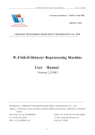
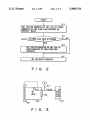
FIG. 1 is a system block diagram of a personal com
puter to which the boot priority changing apparatus of
the present invention is applied;
ci?cally, if the hard disk drive is not attached to the
computer’s main body, the DOS-ROM serves as the
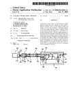
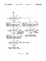
FIG. 2 is a ?owchart showing an IRT routine to be
hard disk drive. The device number “80H” is assigned
executed by the personal computer shown in FIG. 1;
to the HDD and the device number “81H” may be 45
FIG. 3 is a block diagram showing an arrangement
assigned to the DOS-ROM in accordance with the
for detecting the hard disk pack;
speci?cation of the industry standard interface.
However, if the device number “80H” is designated
while the HDD is not attached and a device having the
device number “81H” is present, the boot process can
not be performed due to the constraint of the industry
standard DOS.
SUMMARY OF THE INVENTION
An object of the present invention is to provide a
personal computer having a plurality of bootstrap de
vices and which can execute the boot process in accor
dance with the boot priority preliminarily de?ned de
pending on the connection state of the bootstrap device.
Another object of the present invention is to provide
a personal computer capable of quickly changing the
boot priorities.
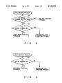
FIGS. 4A and 4B show a ?owchart of a bootstrap
process routine;
FIG. 5 is a ?owchart of an HDD function process;
FIG. 6 is a ?owchart of an FDD function process;
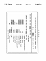
FIG. 7 shows an example of a screen menu of a sys
tem setup;
FIG. 8 is a ?owchart showing an IRT routine of a
second embodiment according to the present invention;
and
FIGS. 9A and 9B show a ?owchart of a bootstrap
process routine in the second embodiment according to
the present invention.
DETAILED DESCRIPTION OF THE
PREFERRED EMBODIMENTS
FIG. 1 is a system block diagram of a personal com
According to a ?rst aspect of the present invention, a
puter to which the boot priority changing apparatus of
the present invention is applied.
devices, and at least one of the bootstrap devices being 65 As shown in FIG. 1, the computer comprises a sys
personal computer comprises: a plurality of bootstrap
detachable to the personal computer; means for detect
ing the connection state of the detachable bootstrap
device; means for preliminarily defming the boot prior
tem bus 10 and components 51 and 11 to 28 which are
connected to the bus 10. These components are: a main
CPU (Central Processing Unit) 11, a basic input and
3
5,448,741
4
output read only memory (BIOS-ROM) 12, a RAM
is supplied with the backup power VBK and stores the
(Random Access Memory) 13 serving as a main mem
video data. The DOS-ROM 26 has a similar format as
ory, a DMAC (Direct Memory Access Controller) 14,
the hard disk pack 20 and stores a disk operating system
a PIC (Programmable Interrupt Controller) 15, a PIT
(DOS) program. The power-supply control interface
(Programmable Interval Timer) 16, and a RTC (Real 5 (PS-IF) 28 connects the power-supply circuit 30 to the
Time Clock) 17.
main CPU 11 through the system bus 10.
The main CPU 11 controls the entirety of the system
When necessary, an AC adapter 29 is plugged into
and executes the various routines represented by the
the main body of the personal computer. It transforms
?owcharts shown in FIGS. 2, 4A and 4B, 5, 6, 8, 9A and
the commercially available AC power into a DC power
9B. The main CPU 11 serves as a host CPU to the
of a predetermined voltage. An expansion connector 40
power control CPU 306 incorporated in the power-sup
is connected at one end to the system bus 10. An expan
ply circuit 30 to be described later.
sion unit is selectively connected to the other end of the
The ROM 12 stores a basic input and output program
connector 40. The power-supply circuit 30 (an intelli
(BIOS). The BIOS includes the program shown in
gent power supply) has a power control CPU (PC
FIGS. 2, 4A and 4B, 5, 6, 8, 9A and 9B. The main CPU 15 CPU) 306. A main battery 31A, which is a chargeable
11 executes the BIOS when the power switch of the
battery pack, is removably mounted on the main body
computer is turned on to read the setup data stored in a
of the personal computer. A sub-battery 31B, which is
speci?c area of the RAM 13 (or register) to determine
also chargeable, is incorporated into the main body of
the system environment, to further read a boot from a
the computer.
hard disk drive (HDD) 20A, and to load a Disk Opera
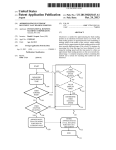
FIG. 2 is a ?owchart showing an IRT (Initialize and
tion System (DOS) program stored in the HDD 20A
Reliability Test) routine which is stored in the BIOS
into the RAM 13. The RAM 13 stores the DOS pro
ROM and executed when the system is powered.
gram, application programs, and various data. Backup
In step 41, the CPU 11 sets the vector address of INT
power VBK is supplied to the RAM 13 from the power
13H to the start address of the FDD floppy disk drive
supply circuit 30. Hence, the data stored in the RAM 13 25 function process, shown in FIG. 6, as a default value.
does not vanish even if the power switch of the com
In step 43, the CPU 11 determines whether or not the
puter is turned off.
hard disk pack 20 is connected. This determination is
The DMAC 14 performs a direct memory access
made by referring to a status register 59, which is shown
control. The PIC 15 can be set by a program. The PIT
in FIG. 3. More speci?cally, as shown in FIG. 3, when
16 can be set by a program and supplies an interrupt
the hard disk pack 20 is attached to the system main
signal to the main CPU 11 under control of the PIC 15
body, the lock mechanism 50 is operated to lock the
when its count reaches a value set by a program. In
hard disk pack 20 into the system main body. The
switch 53 is actuated in cooperation with the operation
of the lock mechanism 50. When the hard disk pack 20
17 is a timer module which has a dedicated built-in 35 is detached from the system main body, the lock mecha
battery (not shown) and measures time; its output repre
nism 50 is released. Accordingly, the switch 53 is turned
sents the present time.
off in cooperation with the release operation. One ter
As is shown in FIG. 1, the personal computer further
minal of switch 53 is connected to the ground and the
comprises an extended RAM 18, a backup RAM 19, a
other terminal thereof is connected to a speci?ed pin of
hard disk pack 20, a ?oppy disk controller (FDC) 20F, 40 the connector 55. The speci?ed pin of the connector 55
a printer controller (PRT-CONT) 21, an I/O interface
is connected to Vcc through a pull-up resistor 57. As a
22, a keyboard controller 23, a display controller 24, a
result, when the hard disk pack 20 is not connected to
response to the interrupt signal, the main CPU 11 exe
cutes a vector interrupt processing routine. The RTC
video RAM 25, a DOS-ROM 26, and a power-supply
the system main body, the high level (logic “1”) HDIN
interface 28. These components are all connected to the
signal is output. When the hard disk pack 20 is attached
system bus 10.
45 to the system, a low level (logic “O”) HDIN signal is
The extended RAM 18 is a large-capacity memory
output. The HDIN signal is stored in the status register
removably inserted in the card slot formed in one side of
59.
the main body of the personal computer, and the backup
power VBK is supplied to the extended RAM 18. The
As per the determination of step 43, if the hard disk
pack 20 is attached to the computer main body, the
backup RAM 19 is also supplied with the backup power 50 CPU 11 sets the vector address of INT 13H toga start
VBK and keeps storing the data required to perform a
address of the hard disk drive (HDD) function process
resume function. The hard disk pack 20 is removably set
in a dedicated housing made in one side of the main
body of the computer, and consists of, for example, a
2.5-inch hard disk drive (HDD) 20A and a hard disk 55
controller (HDC) 20B. The ?oppy disk controller
(FDC) 20F controls an external 3.5-inch ?oppy disk
drive 32 and a 5~inch external ?oppy disk drive 33. The
printer controller 21 is connected to a printer 34, the
printer being externally connected to the computer.
The I/O interface 22 is a universal asynchronous recei
ver/transmitter (UART). If necessary, RS-232C inter
face units are connected to the I/O interface 22. The
shown in FIG. 5. Thereafter, the CPU 11 executes a
process INT 19H (boot process). Note that both INT
3H and INT 19H are a system call and a function re
quest for calling a function of DOS.
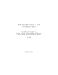
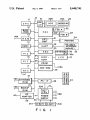
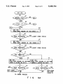
FIGS. 4A and 4B show a ?owchart of the boot pro
cess INT 19H. Suppose ?rst that the hard disk pack 20
is connected and thus the vector address of INT 13H is
directed toward the HDD function process. The CPU
11 determines in step 61 whether or not the boot process
is a normal boot or an HDD boot. The user will have
preliminarily selected either a normal boot or an HDD
boot by using the system setup as shown in FIG. 7, and
keyboard controller (KBC) 23 controls the keyboard
the setup data will have been stored in the backup RAM
36. The keyboard 36 is provided with alphanumeric 65 19. The CPU 11 refers to the backup RAM and deter
keys and function keys including an F1 key 360. The
mines whether the normal boot or the HDD boot has
display controller (DISP-CONT) 24 controls a liquid
been selected. If the determination in step 61 is the
crystal display (LCD) 37. The video RAM (V RAM) 25
normal boot, the CPU 11 sets the device number
5
5,448,741
“00”designating the ?oppy disk drive A in a speci?ed
register (DL register) and calls INT 13H. In this case,
since we are assuming that the hard disk pack 20 is
6
If the read operation is not successful in step 85, the
CPU 11 sets in the DL register “81H” and calls INT
13H. In this case, the determinations of both steps 101
connected, the vector address of INT 13H has been set
and 103 are affirmative. Therefore, the CPU 11 executes
to the HDD function process in FIG. 5. Therefore, the 5 the succeeding DOS-ROM function process. Accord
CPU 11 skips to and executes the HDD function pro
ingly, the CPU 11 reads in step 87 the boot record from
cess. The CPU 11 determines in step 101 whether or not
the DOS-ROM 26. If it is determined in step 89 that the
the device number is “80H” or not. Since in this case the
read operation of the step 87 is successful, the CPU 11
device number has been set to “00” because we have
assumed that the user selected a normal boot, the CPU
executes the boot process from the DOS-ROM 26. If
the read operation is not successful in step 89, the CPU
11 skips to and executes the FDD function process
shown in FIG. 6. The CPU 11 further determines in
step 105 that the device number is not “80H” and it
11 executes the error process.
More speci?cally, the CPU 11 loads the operating sys
tem program (OS) from the ?oppy disk drive A.
nected (described above), the description thereof will
If the boot record can be read out neither from the
On the other hand we are assuming that if the HDD
The previous discussion assumed that the hand disk
pack 20 was connected.
executes the succeeding FDD function process. Thus,
A case wherein the hard disk pack 20 is not con
the CPU 11 reads, in the step 63, the boot record of 15 nected will now be described. In this case, the vector
?oppy disk drive A (FDD A). (The boot record is
address of INT 13H is directed toward the FDD func
stored in cylinder 0, head 0, sector 1.) The CPU 11 then
tion process.
determines in step 65 whether or not the boot record
Assume ?rst that the user has selected the normal
can be read out. If the boot record can ~be read out, the
boot. Since the steps 63 to 69 will proceed in a similar
CPU 11 executes the boot process from the FDD A. 20 fashion as in case wherein the hard disk pack 20 is con
be omitted. Skipping to steps 71, the CPU 11 determines
If the CPU 11 cannot read the boot record from the
that the hard disk pack 20 is not connected. Then, the
FDD A, it reads, in step 67, the boot record of FDD B.
CPU 11 sets in the DL register “80H” and calls INT
The CPU 11 sets the device number “01” designating 25 13H. As a result, the CPU 11 executes step 105 in FIG.
the ?oppy disk drive B in the DL register and calls INT
6. Since the determination of step 105 is affirmative, the
13H. Similar to the case of ?oppy disk drive A, the CPU
CPU 11 executes the DOS-ROM function process.
11 executes the succeeding FDD function process pass
Accordingly, the CPU 11 reads the boot record from
ing through the steps 101 and 105. If the boot record
the DOS-ROM 26. If the read operation of the boot
can be read out from FDD B, the CPU 11 executes the
record is successful, the CPU 11 executes the boot pro
boot process from the FDD B.
cess from the DOS-ROM 26.
FDD A nor from the FDD B, the CPU 11 determines
boot was selected and is determined in step 61, the CPU
in step 71 whether the hard disk pack 20 is connected. 35 11 determines in step 81 whether or not the hard disk
This determination is required in order to change the
pack 20 is connected. Since in this case, the hard disk
device number of the DOS-ROM 26. Continuing with
pack 20 is not connected, the CPU 11 sets in the DL
our assumption that the hard disk pack 20 is connected,
register “80H” and calls INT 13H. Then, the CPU 11
the device number of the DOS-ROM 26 should be
“81H” since the device number “80H” is assigned to the
executes the FDD function process in FIG. 6. The CPU
11 determines in step 105 that the device number is
“80H” and therefore executes the DOS-ROM function
process. Accordingly, the CPU 11 reads the boot re
cord from the DOS-ROM 26. If the read operation of
the boot record is successful, the CPU 11 executes the
and 103 are affu-mative. Therefore, the CPU 11 executes 45 boot process from the DOS-ROM 26.
the DOS-ROM function process. Accordingly, the
A second embodiment of the present invention will
CPU 11 reads in step 73 the boot record of the DOS
now be described with reference to FIGS. 8, 9A and
ROM 26 and determines in step 75 whether or not the
9B.
hard disk pack 20. Thus the CPU 11 sets in the DL
register “81H” and calls INT 13H to execute the HDD
function process shown in FIG. 5. Since the content of
the DL register is “81H”, the determination of steps 101
boot record could be read out. If the boot record was
In the ?rst embodiment, the boot priority is changed
read out, the CPU 11 loads the OS from the DOS-ROM
26 into the main memory 13. If the boot record could be
by designating the normal boot or the HDD boot on the
system setup screen shown in FIG. 7. In the second
embodiment, the boot priority can be quickly changed.
read out, the CPU 11 executes an error process.
On the other hand, if the HDD boot was selected,
then the CPU 11 determines in step 61 that an HDD
Therefore, a DOS command must be input in order to
display the screen shown in FIG. 7, and the system must
boot should occur in step 81 whether or not the hard 55 be rebooted in order to change the boot mode.
disk pack 20 is connected to the computer. Since we
FIG. 8 is a ?owchart of the IRT routine in the second
have assumed that the hard disk pack 20 is connected,
embodiment. The keyboard 36 is provided with a func
the CPU 11 executes step 83. In step 83, the CPU 11 sets
tion key (F 1) 36a for designating the change of the boot
the DL register to “80H” and calls INT 13H. The CPU
priority. The CPU 11 detects the depression of the F1
then executes the HDD function process in FIG. 5. 60 key 36a in the IRT routine. More speci?cally, the CPU
Since the determination of step 101 is affirmative, the
11 initializes and tests registers and devices in step 101.
CPU 11 determines in step 103 whether or not the de
Then, the CPU 11 determines in step 103 whether or
vice number is “81H”. Since the device number is
not the F1 key 36a is depressed. If the determination is
“80H” in this case, the CPU 11 executes the succeeding
affirmative, the CPU 11 sets a ?ag, i.e., sets logic “1” in
HDD function. Accordingly, the CPU 11 reads in step 65 the status register 59. Alternatively, if the determination
83 the boot record from the hard disk pack 20. If the
is negative in step 103, the CPU 11 sets logic “0” in the
read operation is successful in step 85, the CPU 11 exe
speci?c register. Then, the CPU 11 executes the INT
cutes the boot process from the hard disk pack.
19H in step 109.
7
5,448,741
FIGS. 19A and 19B show a ?owchart of the INT
19H process. The reference numerals as in FIGS. 4A
and 4B denote the same steps in FIGS. 9A and 9B, and
a detailed description of these steps will be omitted.
The CPU 11 determines in step 62 whether or not the
personal computer has a normal boot mode wherein a
boot process is executed from a ?oppy disk drive, and a
hard disk drive boot mode wherein the boot process is
executed from a hard disk drive, the method further
?ag (of the status register 59) is “0”. If the ?ag is “0”, it
means‘that the “F1” key 36a is not depressed. Accord
ingly, the CPU 11 executes steps 63 to 79 which have
comprising the steps of:
designating a boot mode by selecting either the nor
mal boot mode or the hard disk drive boot mode,
been described with reference to FIG. 4A.
On the contrary, if it is determined in step 62 that the
the boot mode being displayed by executing a setup
utility of the computer system;
storing the selected boot mode in second storage
?ag is “1”, it means that the boot priority is changed
from the normal boot mode to the HDD boot mode.
Therefore, the CPU 11 executes the steps 81 to 93
shown in FIG. 9B.
8
wherein said steps of depressing, changing and ac
cessing are performed within a single boot process.
2. The method according to claim 1, wherein the
means; and
accessing the bootstrap devices by the boot mode
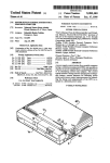
On the other hand, if the determination is the HDD
stored in the second storage means, at power-on of
boot in step 61, the CPU 11 determines in step 80
the computer system.
whether or not the ?ag is “0”. If it is determined that the
3. The method according to claim 2, further compris
?ag is “1”, it means that the HDD boot mode is
ing the steps of:
switched from the HDD boot mode to the normal boot
determining whether the special key is depressed; and
mode. Thus, the CPU 11 executes steps 63 to 79 shown
changing the normal boot mode to the hard disk drive
in FIG. 9A. On the contrary, if the determination in step
mode or vice versa when the special key is de
80 is affirmative, the change of boot priority is not
pressed.
caused. Therefore, the CPU 11 executes the steps 81 to
4. The method according to claim 1, wherein one of
93 shown in FIG. 9B. Thus, in the second embodiment, 25 the bootstrap devices is a detachable type, further corn_
when the system is powered while the F1 key 360 is
prising the steps of:
15
being depressed, the normal boot priority is changed to
detecting the connection of the detachable bootstrap
the HDD boot priority or vice versa.
device;
Additional advantages and modi?cations will readily
changing the boot priority of the bootstrap devices in
occur to those skilled in the art. Therefore, the inven
tion in its broader aspects is not limited to the speci?c
response to the detection of the detachable boot
details, representative devices, and illustrated examples
strap device; and
accessing the bootstrap devices in the order of
shown and described herein. Accordingly, various
modi?cations may be made without departing from the
5. The method according to claim 4, wherein one of
changed boot priority.
spirit or scope of the general inventive concept as de 35 the bootstrap devices being DOS-ROM device, and
further comprising the step of changing the device nurn~
?ned by the appended claims and their equivalents.
ber of said DOS-ROM device in response to the detec
What is claimed is:
tion of the detachable bootstrap device.
1. A method of loading an operating system program
6. The method according to claim 1, further compris
in a computer system which includes a system bus, a
ing the steps of:
setting a data flag representing the special key being
plurality of bootstrap devices coupled to said system
bus, at least one of said bootstrap devices storing an
depressed in ?rst storage means; and
changing the boot priority of each of the bootstrap
operating system program, which method comprises
the steps of:
depressing, during an execution of an initialize rou 45
tine after the computer system is powered, a special
key for requesting a change of the boot priority;
then
devices in accordance with said data ?ag stored in
the ?rst storage means.
7. The method according to claim 1, further compris~
ing the steps of:
determining whether a detachable hard disk drive is
attached in the computer system; and
resetting the boot vector address to the start address
of a hard disk drive boot process when it is deter
mined that the hard disk is attached.
changing the boot priority of the bootstrap devices in
response to depression of the special key; and then
accessing the bootstrap devices in the order of the
changed boot priority in order to load the operat
ing system program,
*
55
60
65
*
*
*
*


![mm [mm [1 um um [11115151116 |])|]1]](http://vs1.manualzilla.com/store/data/005839409_1-1dd2adaaab9a040f039445848c9c3135-150x150.png)