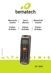
Download DC NEXT 基本操作マニュアル
Transcript
DataCatcher NEXT Ver.1.21B USER’S MANUAL Ver.1.00 / 01-Aug-2000 Please connect probes after the power supply of DC NEXT turns on. Please do NOT turn off the power supply during the configuration. DC NEXT Ver1.21 B USER ’ S Manual DataCatcher NEXT USER’S MANUAL This manual indicates the specifications, basic operations, and other detailed important information that helps you make better use of DataCatcher NEXT(“DC NEXT”). Reproduction in any manner whatsoever without the written permission of Heartland. Data Co.,Ltd. is strictly forbidden. The spesicifications and information of this product in this document are subject to change without notice. We are not responsible for any losses or damages if you use DC NEXT. Trade marks used in this text: Windows, WindowsXP, WindowsVista, Windows7 are registered trademarks of Microsoft Corporation. Other trademarks and trade names may be used in this document to refer to either the entities claiming the marks and names or their products. Heartland. Data Co.,Ltd. disclaims any proprientary interest in trademarks and trade names other than its own. Copyright(C) 2009 Heartland. Data Co.,Ltd. Contents 1. Features .................................................................................................................................................... 1 1-1: General High Speed Communication Line Monitor ........................................................................... 1 1-2: Pitching Function ............................................................................................................................... 2 2. Hardware Specifications ........................................................................................................................... 3 2-1: Catching Line ..................................................................................................................................... 3 2-2: Pitching Line ...................................................................................................................................... 3 2-3: A/D Input ............................................................................................................................................ 3 2-4: External Trigger Input ........................................................................................................................ 3 2-5: Event Output Line .............................................................................................................................. 3 3. Supporting Communication Protocols ...................................................................................................... 4 3-1: 3 Wire Syncronous Serial Communication ........................................................................................ 4 3-2: I2CBUS ............................................................................................................................................. 4 3-3: UART ................................................................................................................................................. 4 3-4: 16bit Parallel ..................................................................................................................................... 4 3-5: Data Logger ....................................................................................................................................... 4 4. Comparative Tables of DC200 and DC NEXT ......................................................................................... 5 5. System Requirement ................................................................................................................................ 6 5-1: OS ...................................................................................................................................................... 6 5-2: PC ...................................................................................................................................................... 6 5-3: CPU ................................................................................................................................................... 6 5-4: Memory .............................................................................................................................................. 6 5-5: Others ................................................................................................................................................ 6 6. Install procedure ....................................................................................................................................... 7 6-1: PC Application.................................................................................................................................... 7 6-2: USB Driver Installaion ...................................................................................................................... 9 7. DC NEXT structure ................................................................................................................................... 9 8. DC NEXT Overview ................................................................................................................................ 10 8-1: Front ................................................................................................................................................. 10 8-2: Back ................................................................................................................................................. 10 8-3: Construction ..................................................................................................................................... 10 9. Hardware handling ..................................................................................................................................11 9-1: DC NEXT board boot procedure ......................................................................................................11 9-2: NOTE ................................................................................................................................................11 10. Basic Operation.................................................................................................................................... 12 10-1: Start Up DC NEXT ......................................................................................................................... 12 10-2: Configuration ................................................................................................................................. 13 10-3: Various File Operation ................................................................................................................... 14 10-4: Display Operation .......................................................................................................................... 15 10-5: Catch Setting Menu ....................................................................................................................... 16 10-6: LOG Display Filter Setting Window ............................................................................................... 17 10-7: Catch Filter Setting Window .......................................................................................................... 18 10-8: Event Filter Setting Window .......................................................................................................... 19 10-9: Trigger Filter Setting Window ........................................................................................................ 20 10-10: Mask Filter Setting Window ........................................................................................................ 22 11. Signal that is able to catch by [ 3WIRE CATCH ]Catch Program ........................................................ 23 11-1: Wave Form of 3 Wire Serial Communication ................................................................................ 23 12. Setting of [ 3WIRE CATCH ]Catch Program .................................................................................... 24 12-1: 〈Catch Type Setting〉 the setting contents in this tag .................................................................. 24 12-2: 〈Channel1〉〈Channel2〉〈Channel3〉 the setting contents in this tag ........................................... 25 12-3: Connector List ............................................................................................................................... 30 12-4: Restrictions .................................................................................................................................... 30 13. Signal that is able to transmit with [ 3WIRE_PITCH ]Program ............................................................ 32 13-1: Supporting Signal <3Wire> ........................................................................................................... 32 14. The Setting of [ 3WIRE_PITCH ]Program ........................................................................................... 33 14-1: 〈Catch Type Setting〉 the setting contents in this tag .................................................................. 33 14-2: Functions ....................................................................................................................................... 33 14-3: The Setting of Pitching Box <Transmitting Data Format> ............................................................ 34 14-4: Basic Operation ............................................................................................................................. 34 14-5: Connector List ............................................................................................................................... 35 14-6: Restrictions .................................................................................................................................... 35 15. The Setting of [ I2CBUS_100K/400K ]Catch Program .................................................................... 36 15-1: <Catch Type Setting〉 The setting contents in this tag ................................................................. 36 15-2: <Channel1><Channel2> The setting contents in this tag ............................................................. 37 15-3: Conector List ................................................................................................................................. 38 15-4: Restrictions .................................................................................................................................... 39 16. Signal that is able to catch with [ I2CBUS_100K/400K ]Catch Program......................................... 40 16-1: Type that “start condition” and “end condition” is a pair ................................................................ 40 16-2: Type with the restart between “start condition” and “end condition” ............................................. 40 17. Signal that is able to transmit with I2S Pitching Function .................................................................... 41 17-1: Supporting Waveform < I2C > ....................................................................................................... 41 17-2: Connection Method < I2C > .......................................................................................................... 41 18. The Setting of I2C_BUS Pitching Function .......................................................................................... 42 18-1: Functions ....................................................................................................................................... 42 18-2: The Setting of Pitching Box<Transmit Data Format> ................................................................... 42 18-3: Basic Operation ............................................................................................................................. 42 18-4: Connector List ............................................................................................................................... 43 18-5: Restrictions .................................................................................................................................... 43 19. Signal that is able to catch with [ UART ] Catch Program ................................................................... 44 19-1: Low active signals ......................................................................................................................... 44 20. The Setting of [ UART ]Catch Program................................................................................................ 45 20-1: <Catch Type Setting> The setting contents in this tag ................................................................. 45 20-2: <Channel1><Channel2> The setting contents in this tag ............................................................. 46 20-3: Connector List ............................................................................................................................... 49 20-4: Restrictions .................................................................................................................................... 49 21. Signal that is able to transmit with UART Pitching Function ............................................................... 50 21-1: Low active signals ......................................................................................................................... 50 21-2: Connection Method ....................................................................................................................... 50 22. The Setting of I2C_BUS Pitching Function .......................................................................................... 51 22-1: Functions ....................................................................................................................................... 51 22-2: The Setting of Pitching Box<Transmit Data Format> ................................................................... 51 22-3: Basic Operation ............................................................................................................................. 51 22-4: Connector List ............................................................................................................................... 52 22-5: Restrictions .................................................................................................................................... 52 23. Signal that is able to catch with [PARA_CATCH ] Catch Program ...................................................... 53 23-1: Parallel communication 16Bit DATA width signals ........................................................................ 53 24. The Setting of [ PARA_CATCH ]Catch Program ................................................................................. 54 24-1: <Catch Type Setting> The setting contents in this tag ................................................................. 54 24-2: <Channel1><Channel2> The setting contents in this tag ............................................................. 55 24-3: Connector List ............................................................................................................................... 60 24-4: Restrictions .................................................................................................................................... 61 25. [ DATA_LOGGER ]Catch Program ...................................................................................................... 62 25-1: Catch of digital signal .................................................................................................................... 62 25-2: Catch of analog signal ................................................................................................................... 62 26. About the setting of Data loger ............................................................................................................ 63 26-1: <Catch Type Setting> the setting contents in the tag ................................................................... 63 26-2: <AD MASK/LEVEL DATA> the setting contents in the tag ........................................................... 64 26-3: Connector List ............................................................................................................................... 65 27. How to make Command Analyzing Definition File ............................................................................... 66 27-1: Feature(Useful to do this).............................................................................................................. 66 27-2: Restriction/Limitation ..................................................................................................................... 66 27-3: Section........................................................................................................................................... 67 27-4: Definition........................................................................................................................................ 71 27-5: Form .............................................................................................................................................. 72 27-6: String Pattern Definition ................................................................................................................ 73 27-7: Special Definition ........................................................................................................................... 74 27-8: Description Example and Display Image ...................................................................................... 75 28. Additional function ................................................................................................................................ 79 28-1: OS .................................................................................................................................................. 79 28-2: Log window, The improvement of the measuring time indication after a setup of a filter ............... 79 28-3: The number of sections was changed. ......................................................................................... 79 DC NEXT Ver1.21 B USER ’ S Manual 1.Features 1-1:General High Speed Communication Line Monitor Data catcher DC2000 is the line monitor for embedded systems development, which was developed for the purpose of debugging of the communication of a microcomputer. Formerly, to confirm the communication data, a signal was confirmed directly with digital oscilloscope etc. In the case that LSI that is connected with a microcomputer and serial or parallel interface is used and the system that does a communication with a microcomputer fellow, when I develop it. Conventional method(digital oscilloscope) 1/0 bit pattern is transformed into a numerical value to confirm the contents of a communication. And, the procedure that understands the processing contents corresponding to the numerical value in reference to the specifications of LSI was necessary. Also, it was difficult to analyze the whole processing, because the surveillance in the long time is impossible in a digital oscilloscope. Inovative method(DC NEXT) Main Features of DC NEXT (1)Dividing communication data as packet it displays it every 1 packet. (2)It displays it clearly with the letter that the user defined communication data. (3)The data that received it displays it with the real time. (4)The interval of packet and packet it can measuring with 0.1/1.0msec resolution. Therefore, the inspection of the communication timing is easy. We recommend DC NEXT to the following people. Software Engineerof Embeded System Please use it for the reduction of debugging work. Evaluation Engineer of Embeded System Please use it with the evaluation of software. Hardware Engineer of Embeded System Please use it for the unification of the intention with a software engineer. By using DC NEXT, the debugging work time of communication processing can be reduced substantially. DC NEXT Ver1.21 B USER ’ S Manual 1-2:Pitching Function This function can output the various kinds of signals. You can use DC NEXT not only as a line monitor but as a command transmitter. Supporting protocols are 3 wire synchronous serial communication, I2C, and UART. Features (1) DC NEXT can transmit data up to 16 bytes per 1 packet. (2) DC NEXT has various FORMAT settings like CLOCK Frequency, CLOCK Edge, STB Edge, and so on. 2 DC NEXT Ver1.21 B USER ’ S Manual 2.Hardware Specifications 2-1:Catching Line a) Max Channel b) Input Format c) Input Voltage Range d) Input Level e) Max Input Frequency : 3CH : PULLDOWN to GND(1MΩ) : 0V to 5V : VB=1.8V , Hi=1V , Lo=0.5V : VB=3.3V , Hi=2V , Lo=0.9V : VB=5V Hi=3V , Lo=1.5V : 20MHz 2-2:Pitching Line a) Max Channel b) Output Format / Level c) Output Level d) Max Output Frequency e) Max Output Current : 1CH : Be equivalent to catching input Level (3 wire synchronous serial, UART) : Nch Open Drain(I2C) : 0V to 5V : 10MHz : VB=3.3V , 5.2mA : VB=5V , 7.8mA : VB=EXT(1.8) , 1mA 2-3:A/D Input a) Max Channel b) Input Format c) Input Voltage Range d) Sampling Frequency e) AD Input Resolution : 8CH : PULLDOWN to GND(100KΩ) : 0.1V to 4.9V : 1.25KHz / 6.25KHz : 8bit 2-4:External Trigger Input a) Input Line b) Input Format c) Input Voltage Range d) Input Level : 1CH : PULLDOWN to GND(1MΩ) : 0V to 5V : VB=1.8V , Hi=1V , Lo=0.5V : VB=3.3V , Hi=2V , Lo=0.9V : VB=5V , Hi=3V , Lo=1.5V 2-5:Event Output Line a) Output Line b) Output Format c) Output Level d) Input Level : 1CH : Be equivalent to catching input Level : 0V to 3.3V : VB=3.3V , 3mA : VB=5V , 5mA : VB=EXT(1.8V) , 1mA 3 DC NEXT Ver1.21 B USER ’ S Manual 3.Supporting Communication Protocols 3-1:3 Wire Syncronous Serial Communication - 3 wire synchronous serial communications has CLOCK, DATA, STB. - Supported clock frequency Max 20MHz. - 3ch is able to be used simultaneously. - Even the communication type that there is not STB is able to take it as packet by the change of "the type file". - Enable catch/pitch the communication data. 3-2:I2CBUS - Supported Max 4MHz Clock Frequency - You can use 2ch simultaneously - Enable Data Pitch in Normal Mode(100KHz) or Fast Mode(400KHz). 3-3:UART - Supporting bitrate from 110bps to 921600bps - You can use 2ch simultaneously - Enable catch/pitch the communication data. 3-4:16bit Parallel - Supported data lines Max 16 bit. - Supporting Max 2MHz Clock Frequency 3-5:Data Logger - CMOS Level Digital input line : 8ch. Sampling rate10KHz / 50KHz. - AD convert ing input from 0.1V to 4.9V, 8bit resolution. : 8ch Sampling rate1.25KHz / 6.25KHz. 4 DC NEXT Ver1.21 B USER ’ S Manual 4.Comparative Tables of DC200 and DC NEXT Function / SPEC DataCatcher NEXT Three wire synchronous serial communicationData Clock Frequency Transmit Capacity Data catch Restriction 1 Restriction 2 Data pitch Data catch Output Frequency Clock Frequency Transmit Capacity Restriction Data pitch Output Frequency Clock Frequency Transmit Capacity Restriction 1 Data catch Restriction 2 Restriction 3 Data pitch DC2000 Output Frequency UP! 2 MHz MAX 20 MHz MAX UP! 8 Kbps 80 Kbps One byte reception after, the next clock such time when becomes possible and receives. UP! 5 us 50 ns SUCH TIME WHEN THE STB SIGNAL OCCURS AND THE NEXT CLOCK BECOME POSSIBLE AND RECEIVE. UP! 5 us 1 us NEW 10MHz MAX UART *1 UP! 300 BPS to 57600 BPS 110 BPS to 921600 BPS UP! 38400 bps 57600 bps Possible to use with 921600BPS2CH UP! 57600 BPS is 1CH only. simultaneously. NEW 110 BPS to 921600 BPS I2C BUS *2 UP! 500 KHz MAX 4 MHz MAX UP! 8 Kbps 80 Kbps The option board is unnecessary.Possible ExpanderBoard is necessary for UP! to use with 4MHz MAX2CH 500KHzMAX. 1CH only. simultaneously. One byte reception after, the next clock such time when becomes possible and receives. UP! 5 us 100 ns 3Such time when stop condition occurs and the next clock become possible and receive. UP! 5 us 1 us NEW 100KHz / 400KHz Parallel communicationsData Clock Frequency Transmit Capacity Input Data Bit Data catch Restriction 1 Restriction 2 UP! 200 KHz MAX 2 MHz MAX UP! 1 Kbps 10 Kbps UP! 8 Bit MAX 16 Bit MAX DATA holding time(time from clock high edge to DATA fix) UP! 2 us 100 ns SUCH TIME WHEN THE STB SIGNAL OCCURS AND THE NEXT CLOCK BECOME POSSIBLE AND RECEIVE. UP! 5 us 1 us Data logger Sampling time(frequency) Digital input (CMOS) A/D input (0V~5V) A/D input resolutionetc. 20usec(50KHz) /100usec(10KHz) 9 lines 8 lines 8 Bit Maximum data log number Connection with PC 100,000 RS-232C - - - - 20usec(50KHz) / 100usec(10KHz) 8 lines 8 lines 8 Bit UP! NEW 1,000,000 USB2.0 <Possible to switch> 3.3V/5V/1.8V to 5V(EXT) <Threshold level> VB = 1.8V HI = 1V : Lo = 0.5V VB = 3.3V HI = 2V : Lo = 0.9V VB = . 5V .HI = 3V : Lo = 1.5V Enable delaying timing for Data fix edge of Clock signal.This one enable to catch non-spire signal easily. Etc Input voltage range 0 to 5V <Threshold Level> HI = 2V : Lo = 0.8V (TTL Level) NEW NEW Function easy data catch feature *1 : National Semiconductor UART 16550 compliance. *2 : the Philips IICbus v2.1 compliance. 5 DC NEXT Ver1.21 B USER ’ S Manual NOTE: 1, Enable to use the setting files, Log/Commnad/Type/Condition files, for DC2000 to DC NEXT 2. Transmit Capacity. - Performance value as data catching 1ch in each communication - Enable to catch the communication data within Transmit Capacity - Displayed the message “FULL” on channel cell of log when Transmit Capacity over. 5.System Requirement 5-1:OS Microsoft Windows XP, Windows Vista, Windows 7, 5-2:PC PC/AT Compatible that above OS can work on. 5-3:CPU Over 800MHz Intel Pentium Processor recommended 5-4:Memory Over 256MB recommended 5-5:Others 4MB available HDD space USB 2.0 port 6 DC NEXT Ver1.21 B USER ’ S Manual 6.Install procedure 6-1:PC Application 1. Insert the attached CD-ROM "DC NEXT Install Disc" to CD-ROM drive, then click the icon [dcnext_Install.exe.] 2.Click [Next] after [Welcome to the Data Catcher NEXT Setup Wizard] shown. 3. Click [Next] after [Select Installation Folder] shown. NOTE: “C:/Program Files/HeartLandData/DC NEXT” is selected as default setting. Please click [NEXT] if it is available for you. If you would like to install to another folder, please click [Browse] and then select the folder. 4.Click [Next] after [Confirm Installation] shown. 7 DC NEXT Ver1.21 B USER ’ S Manual 5.[Installing Data Catcher NEXT] is shown during installing. 6.Click [Close] after [Installation Complete] shown. Please take out the CD-ROM "DC NEXT Install Disc" after click [Close]. Installation completed. 8 DC NEXT Ver1.21 B USER ’ S Manual 6-2:USB Driver Installaion 1. Connect DC NEXT body with PC by the attached USB cable. 2. Power up DC NEXT. Connect AC adapter with DC NEXT, then switch [POWER] ON in front of DC NEXT body 3. Confirm lighting of LED. [POWER] LED blue light when power up D NEXT. [CONNECT] LED lights after 20sec from power up. CAUTION : Power on while unfastening prove. 4. The Found New Hardware Wizard is appears. Select [Install from a list or specific location (Advanced)] and then click [Next]. 5. Select [Search for the best driver in these locations] . 6. Check [Include this location in the search] then click [Browse] . Select “../ HeartLandData/DC NEXT/driver”, and then click [OK] . Confirm folder path shown in text box and then click [Next]. 7. Message [ “HLDC DataCatcherNEXT ” has not passed Windows Logo testing to verify its compatibility with WindowsXP.] should appears.Click [Continue Anyway]. 8. [Completing the Found New Hardwre Wizard] is appears. Click [Finish] Installation complete. 7.DC NEXT structure DC NEXT catches the communication data on target board and uploads it to PC. PC receives the data, analizes and then shows on the monitor. PC DC NEXT Target Borad Probe DataCatcher NEXT USB Upload Micon<->LSI Communication Data Communication Data Catch 9 Catch Data Display DC NEXT Ver1.21 B USER ’ S Manual 8.DC NEXT Overview 8-1:Front EXT GND CATCH LED PITCH LED VB SW CONNECT LED POWER Prove Connector pin 8-2:Back MiniUSB Connector Power supply Connector POWER SW LAN Connector 8-3:Construction GND EXT VB SW CATCH LED PITCH LED CONNECT LED POWER Prove Connector pin POWER SW MiniUSB Connector LAN Connector Power supply Connector GND terminal for DC NEXT board. Connect with target system by attached GND cable Input terminal for external power supply. Connect with power supply to adjust input voltage by it. SW to change the input voltage range for DC NEXT. Selectable 3.3V or 5V or EXT. Please select EXT when you use the external power supply. Lighting while catching the communication data. Lighting while pitching the communication data. Lighting while connecting DC NEXT electrically. Lighting while power supplying to DC NEXT board. Connect the communication line by using attached prove. Posision depends on the communication format. Please refer to Connector List. Power SW for DC NEXT board. Connect with PC by using attached USB cable. Not used. Connect with attached AC adapter. 10 DC NEXT Ver1.21 B USER ’ S Manual 9.Hardware handling 9-1:DC NEXT board boot procedure 1. Connect with PC. Connect PC with DC NEXT BOARD by attached USB cable. 2. Power on. Power on by POWER SW after insert AC adapter. [POWER] lights blue after Power on. [CONNECT] lights after 20sec from Power on. Setup complete. 3. Start Application. Boot PC Application. Please refer to “10-1:DC NEXT boot” . 4. Connect GND. Connect with DC NEXT board attached GND cable. 5. Select the input voltage range. Select the input voltage range by VB SW. Connect EXT pin with target board VDD when DC NEXT catches the data on BUS line not over 3.3V. 6. Connect communication line. Connect communication line with DC NEXT board attached prove cable. Posision depends on the communication format Please refer to Connector List. 9-2:NOTE Please take care following items for hardware: - Power on while unfastening prove. - Connect target GND with DC NEXT board GND. - Do not power off during configuration by changing the Catch Program. - It takes time 20sec for firmware update by configuration. Do not power off during this one. - Check the power setting of your PC when you catch the data long long time to prevent power cut for HDD automatically or Windows transmitring to standby mode. 11 DC NEXT Ver1.21 B USER ’ S Manual 10.Basic Operation 10-1:Start Up DC NEXT 1.Double-click the [DC NEXT] Icon or Select the[Data CatcherNext]Program. 2.Select CatchProgram. Data log window is shown by select Catch Program and then click [OK]. If [Cancel] is clicked, data log window is shown as 3WIRE_CATCH. 12 DC NEXT Ver1.21 B USER ’ S Manual 10-2:Configuration ① ③ ② ④ ⑤ ⑥ 1. Log window is shown. 1 The catch program name that selected it is shown. 2 The file name of the catch type that selected it is shown. 3 The definition file name for the command analysis in the selection is shown. 4 Start No. of catch data is shown. 5 Completion No. of catch data is shown. 6 The data number that received it is shown. The communication data of 1,000,000 packet can be received. Also, communication packet over 1,000,000 packet case receive it with the ring form. 2. Configuration. Application checks firmware of DC NEXT BOARD after click [Catch Start]. It starts to catch the communication data if [CatchProgram] conforms to NEXT board firmware. If it does not conform, following message is shown on the monitor. And then the firmware corresponding CatchProgram is written. 13 DC NEXT Ver1.21 B USER ’ S Manual It takes 20sec. Available after DC NEXT BOARD [CONNECT] lighting. [CAUTION] Please do NOT turn off the power supply during the configuration. 10-3:Various File Operation The file menu does the save of reading and, log file of a/the type file, command file. -A catch program change --- This does the change of the catch program. In this way, even the catch data is clear. -I open a log file --- The log file of the log form is opened. The display contents are displayed with the contents that were displayed to before. -A log file save --- This preserves catch data with the log form. 14 DC NEXT Ver1.21 B USER ’ S Manual -I save it in a text form --- The catch data is preserved with the text form. This preservation form is the one that divided each data period with a ",". Therefore the editing is possible with EXCEL etc. -Command file choice --- This reads the command file. The extension of this file is cmd. -I open a type file --- This reads the typ file. The setting contents for the communication type are preserved, in a type file. -A type file save --- The setting contents for the communication type are preserved. Please refer to the manual for each catch program about the setting of a catch type. -I open a condition file --- This reads the bit file. The setting contents for the various kinds filter are preserved, in a bit file. -A condition file save --- This preserves the setting contents of the various kinds condition to the bit file. -The end of an application --- The data catcher is ended. 10-4:Display Operation This section explains it about the operation of display data. 15 DC NEXT Ver1.21 B USER ’ S Manual - Log Display filter setting : Setting for limitation of log data display. Log Display filter setting window is opened by select this one. - MON Display filter setting : Setting for limitation of monitor data display. MON Display filter setting window is opened by select this one. - Display item setting : Setting for display type of items. Display item setting window is opened by select this one. - Catch data clear : Clear the displayed data on the monitor. 10-5:Catch Setting Menu By this menu, you can set up filter condition and, event, trigger condition of catch data. -Catch condition setting You can reject, and also receive the only communication data that agreed with the condition, by setting up the filter condition. When this item is selected the catch filter setting window opens. 16 DC NEXT Ver1.21 B USER ’ S Manual -Event output condition setting When the data that agreed with a designated condition is received the event can be output. When this item is selected the event filter setting window opens. -Trigger condition setting When the data that agreed with the condition is received the condition that does the catch start/stoppage can be set up. When this item is selected the trigger condition setting window opens. -Catch type setting Please refer to the manual for each catch program. 10-6:LOG Display Filter Setting Window Following window is opened after select Log Display filter setting. [About each setting content ] -I set it as the filter which I do not display [I set it as a filter to display usually] check box Only the data in accord with a/the condition does not display it in the case of on. Only the data in accord with the condition displays it in the case of off. This check box is common setting for all filter setting.。 17 DC NEXT Ver1.21 B USER ’ S Manual - Don‟t Display when Same Channel in Same Data. ON : When same data are catched over twice, 2nd or later are not shown. OFF : All catched data are shown withour change. This check box is common setting for all filter setting. -Filter effective check box You can do the filter condition that was checked effectively. The check is not applied about the condition without being done. -MASK Bit setting button When you push this button the setting window of the mask bit can be opened. 10-7:Catch Filter Setting Window Following window is opened after select Catch filter setting. [Settings] - [Don‟t Catch Filter[Catch Filter usually]] check box. ON : Filter setting is used as not to Catch the data conforming setting data. OFF : Filter setting is used as to Catch the data conforming setting data. This check box is common setting for all filter setting.。 18 DC NEXT Ver1.21 B USER ’ S Manual -Filter effective check box You can do the filter condition that was checked effectively. The check is not applied about the condition without being done. -MASK Bit setting button When you push this button the setting window of the mask bit can be opened. 10-8:Event Filter Setting Window When [Event output condition setting] is selected this window opens. -EVENT effective check box Available only filter condition checked. Not available others. EVENT output port becomes 0V with a catch start. When catch data agrees with the setting condition EVENT output port becomes 5V. -MASK Bit setting You can open the setting window of a/the mask filter, by clicking this button. 19 DC NEXT Ver1.21 B USER ’ S Manual 10-9:Trigger Filter Setting Window When trigger condition setting is selected the following window opens. - Page1 - -「Using TRG as external trigger」check box - You can select the trigger port. - [I catch it if I grew, and it is started by high] Radio button - Detecting that the condition of the trigger port became HI the catch is started. - [It is Catch movement during high periods] Radio button - Trigger port does a catch only the period of HI. - [I catch it if I grew, and it is started by low] Radio button - Detecting that the condition of the trigger port became LOW the catch is started. - [I catch it during period of low and work] Radio button - Trigger port does a catch only the period of LOW. 20 DC NEXT Ver1.21 B USER ’ S Manual - Page 2- -Catch start is effective check box - Catch is started by the detection of the data that agreed with the setting condition, by turning on this check box. -The catch end is effective check box - Catch is stopped by the detection of the data that agreed with the setting condition, by turning on this check box. -MASK Bit setting - You can open the setting window of a/the mask filter, by clicking this button. 21 DC NEXT Ver1.21 B USER ’ S Manual 10-10:Mask Filter Setting Window By clicking the MASK Bit setting button that is in a various kinds filter setting window the following window is displayed. -CH No. Dropdown list - You can select the channel that sets up the mask filter. -Count Dropdown list - You can designate it with Byte or Bit unit about the length of the communication packet that applies the setting condition. The unit differs by each catch program. -ALL Clear button - All the setting conditions are initialized. -Bit Filter field - You can set up the filter condition with a bit unit. - Data No. Dropdown menu - You can select DATA No. that sets up the filter condition. - Radio button for bit setting - You can designate the data that becomes a filter condition every 1 bit. X shows don't care. 22 DC NEXT Ver1.21 B USER ’ S Manual 11.Signal that is able to catch by [ 3WIRE CATCH ]Catch Program 11-1:Wave Form of 3 Wire Serial Communication DC NEXT supports the following “3 wire serial communication. CLOCK DATA STB Time between Byte. There is a STB signal general "3 line synchronous serial communications", the catch is possible regarding the type that there is not a STB signal. - Form that settles communication packet in the time between Byte. - Form with the data that designates the length of communication packet into communication data. - Form with the data that instructs the completion of communication packet. - Form with the data that settles the length of communication packet. 23 DC NEXT Ver1.21 B USER ’ S Manual 12.Setting of [ 3WIRE CATCH ]Catch Program <Channel Setting> the dialog box can be opened with [Catch setting (L)]-[Catch type setting (P)] of the click. By changing this setting various 3 wire serial communications can be received. The setting contents it does explanation below. 12-1:〈Catch Type Setting〉 the setting contents in this tag [Max catch data of each channel] <Max Length> The number of the DATA line that is displayed to the screen is set up. When Max Length is set up with 10 D01-D10 is displayed to the DATA line. MAX value is 32. [Setting of catch data measurement time] Data catcher measures the time from the settlement of the settlement to, present communication packet of the communication packet of before and display. You can set up the resolution in measuring time. 24 DC NEXT Ver1.21 B USER ’ S Manual 12-2:〈Channel1〉〈Channel2〉〈Channel3〉 the setting contents in this tag [Choice of CLOCK frequency band] Select CLOCK frequency band of communication signal. Enable to catch although select [OFF]. Enable to catch tolerably for blunt Hi/Low edge. * When DC NEXT cannot catch target signal, please use this one. [Choice EDGE of CLOCK] Select edge of CLOCK. [DELAY TIME] Enable DELAY setting for the timing that CLOCK line checks DATA signal. OFF : Checking Data signal by edge of CLOCK signal. Enable to catch tolerably for blunt Hi/Low edge. * When DC NEXT cannot catch target signal, please use this one. 25 DC NEXT Ver1.21 B USER ’ S Manual * When DC NEXT cannot catch target signal, please use this one. [Choice of bit order] Serial transmission method is selected. [Edge choice of STB] EDGE of STB signal is selected. [Choice of the order of catch data] The display turn of catch data is set up. Clock Data1 DATA Data2 Data3 STB The following screen shows case that turned on [In order of catched time] option button. CH 1 24 DATA1 DATA2 DATA3 26 DC NEXT Ver1.21 B USER ’ S Manual The following screen shows case that turned on [In order of near STB (latch)] option button. CH 1 24 DATA3 DATA2 DATA1 [Do you invert the logic of catch data?] Select the logic inverted or not. [All the catch data at the time of [0]] The processing method of case that all the data of communication packet were 0 is set up. [All the catch data at the time of [1]] The processing method of case that all the data of communication packet were 1 is set up. [In data decision other channel data?] A certain channel sets up it about the processing method of the data that received it with other channels in the time that settled communication packet, in middle that is receiving communication data. * Please refer to “Restriction”. [Max catch data] <Max Length> The number of the DATA line that is displayed to the screen is set up. When Max Length is set up with 10 D01-D10 is displayed to the DATA line. MAX value is 32. Please set up it short than " Max catch data of each channel " of page before. 27 DC NEXT Ver1.21 B USER ’ S Manual [If I caught a max byte?] You can set up it about the processing method of case that received the data number that set up it with "Max catch data". - On of " Discard the data from older data " the option button This receives it while discarding old data until communication packet settles. - On of " Set the data as a continuation handling " the option button This receives all the data, until communication packet is settled. If the byte number of communication data, becomes "Max catch data" that designated the data to there is displayed. The data after that continuously displays it as data. The following item sets up it about the condition that settles communication packet. [It is decided that it is data to point out a last byte] In the case that there is the data that shows the final byte the value of 0x00h-0xffh is set up. Also, off is set up in the case that there is not the data that shows the final byte. [It is decided that it is time after 1 byte receipt of a message] Communication packet is settled in the time between BYTE. As for the setting value, the selection is possible among 001-100 and the unit is msec. When "off" was selected this setting becomes ineffective. [There is a byte to appoint length] The data that designates the length of communication packet sets up this to be included to communication packet. -The several byte : In the case that the data that designates the length of communication packet is included the position of the data is set up. This value is to 01-32. When "off" was selected this setting becomes ineffective. -Revision : For example the revision value is set up, in the case that the data of the position that the data of STX and ETX are included in communication packet and set up in the above does not include STX and ETX. This value is to 01-32. In the case that there is not revision data 00 are set up. 28 DC NEXT Ver1.21 B USER ’ S Manual [There is a byte to let length settle] In the case that the data that settles the length of communication packet is included the position of the data is set up. This value is to 01-32. When "off" was selected this setting becomes ineffective. The length of the communication packet corresponding to this data corresponds it like the next page by the type file.( The example of the next page is case with regard to channel 1) For example, and the value (the position of data) "18" are set up and please edit as follows, to set up the length of communication packet with 16Byte. (Matrix form) -Actual file contentsCH1_COMMAND_STB=00 ; : 00 01 02 03 04 05 06 07 08 09 0a 0b 0c 0d 0e 0f $00=00,00,00,00,00,00,00,00,00,00,00,00,00,00,00,00 $10=00,00,10,00,00,00,00,00,00,00,00,00,00,00,00,00 $20=00,00,00,00,00,00,00,00,00,00,00,00,00,00,00,00 $30=00,00,00,00,00,00,00,00,00,00,00,00,00,00,00,00 $40=00,00,00,00,00,00,00,00,00,00,00,00,00,00,00,00 $50=00,00,00,00,00,00,00,00,00,00,00,00,00,00,00,00 $60=00,00,00,00,00,00,00,00,00,00,00,00,00,00,00,00 $70=00,00,00,00,00,00,00,00,00,00,00,00,00,00,00,00 $80=00,00,00,00,00,00,00,00,00,00,00,00,00,00,00,00 $90=00,00,00,00,00,00,00,00,00,00,00,00,00,00,00,00 $a0=00,00,00,00,00,00,00,00,00,00,00,00,00,00,00,00 $b0=00,00,00,00,00,00,00,00,00,00,00,00,00,00,00,00 $c0=00,00,00,00,00,00,00,00,00,00,00,00,00,00,00,00 $d0=00,00,00,00,00,00,00,00,00,00,00,00,00,00,00,00 $e0=00,00,00,00,00,00,00,00,00,00,00,00,00,00,00,00 $f0=00,00,00,00,00,00,00,00,00,00,00,00,00,00,00,00 [Editing of the type file] The type file is opened with a/the text editor. Please use it in the case that a direct type file is edited. The contents that changed it with channel setting window click "OK" the button once, in the case that they were already done a change, because they are not written in the file until they preserve the type file and choose from "File" the menu "TYPE file save" and please do type file editing once again, after they preserved it. By clicking this button the following information window opens. 29 DC NEXT Ver1.21 B USER ’ S Manual 12-3:Connector List Ch No 1 2 3 Pin No 1 2 4 5 6 8 9 10 12 47 48 Name Contents CH1_CLK CH1_DATA CH1_STB CH2_CLK CH2_DATA CH2_STB CH3_CLK CH3_DATA CH3_STB EVENT TRIG CH1 CLOCK signal input. CH1 DATA signal input. CH1 DATA fix signal input. CH2 CLOCK signal input. CH2 DATA signal input. CH2 DATA fix signal input. CH3 CLOCK signal input. CH3 DATA signal input. CH3 DATA fix signal input. Event signal output by setting of Event filter. External trigger input. CAUTION: - Connect target GND with DC NEXT board GND. Please ground even so the catch data is unsteady. - Power DC NEXT before connecting probe with communication line. If not, it cause of trouble. - Need to connect each CLOCK input with target CLOCK signal when multi channel data catching. 12-4:Restrictions The highest frequency of a reception possible clock Such time when the STB signal occurs and the next clock become possible and receive One byte reception after, the next clock such time when becomes possible and receives 25ns 50ns 50ns 20MHz 1usec 50nsec 1us CLOCK 50ns DATA STB * CLOCK edge is delayed internally when [Choice of CLOCK frequency bgand] and [DELAY TIME] are used at the same time. Since the data catch timing depends on the setting value, unsuitable setting may delay the timing, and then the catch data is not shown correctly. 30 DC NEXT Ver1.21 B USER ’ S Manual - Feature : Clear another channel data when data is fixed. More then 1ms More then 1ms CLOCK DATA STB_1 STB_2 - Needed over 1msec in upper case from packet data fixing to next clock signal. 31 DC NEXT Ver1.21 B USER ’ S Manual 13.Signal that is able to transmit with [ 3WIRE_PITCH ]Program 13-1:Supporting Signal <3Wire> EX. CLK=10MHZ 50ns 400ns 800ns CLOCK 100ns DATA STB - Enable CLOCK frequency : 100KHz/500KHz/1MHZ/5MHz/10MHz. - Needed 4 clocks wait time from 1Byte transmitred to next CLOCK pulse. - Needed 8 clocks wait time of selected frequency from last CLOCK pulse to STB edge. EX1. DEFAULT : LOW/CLOCK_EDGE : LOW/DATA_ACTIVE : LOW/STB : HI CLOCK 100ns DATA STB EX2. DEFAULT : HI/CLOCK_EDGE : HI/DATA_ACTIVE : HI/STB : HI CLOCK DATA STB 32 DC NEXT Ver1.21 B USER ’ S Manual 14.The Setting of [ 3WIRE_PITCH ]Program 14-1:〈Catch Type Setting〉 the setting contents in this tag By clicking [Catch setting (L)]-[Catch type setting (P)] the < Channel Setting > dialog box is shown. Please set the 3WIRE send data. Please set up it in accordance with the following explanation. [Choice of CLOCK frequency] Select CLOCK frequency [Choice of CLOCK/DATA FORMAT] <DEFAULT> Select the default CLOCK setting. <CLOCK_EDGE> Select the signal edge of Latch. <DATA_ACTIVE> Select the active statement of DATA signal. [Choice of STB Type] Select the type of STB signal. 14-2:Functions ・Enable to transmit 1packet data frexibly during data catch. ・Enable to transmit max data length. ・Enable to set transmitring format CLOCK frequency, 33 DC NEXT Ver1.21 B USER ’ S Manual 14-3:The Setting of Pitching Box <Transmitting Data Format> ・Max length of text is 32 charactors, 16Bytes. ・Please input the data as HEX. NOTE : Enable charactors are ”0”-”9”, “A”-“F”. 32 charactors. 14-4:Basic Operation 1. Connect the prove with 3wire line on target board. Please refer to ”14-5 : Connector List ” 2. The window “Pitching box” is opened after click [Catch Start(A)]-[Pitching box(P)]. 3. Input the transmit data in text box by HEX. Max 16 bytes. Enable charactors are ”0”-”9”, ”A”-”F”. 32 charactors. 4. Transmit the data by click [Send] bottun. 5. Clear the data by click [Clear] bottun. 6. Close the “Pitching Box” window by click [Cancel] bottun. 34 DC NEXT Ver1.21 B USER ’ S Manual 14-5:Connector List Ch No 1 Pin No 29 30 32 Name CLK DATA STB Contents CH1 CLOCK signal output. CH1 DATA signal output. CH1 DATA fix signal output Please modify your target board like below when DC NEXT is connected with target. ↓Line Open <Transmitted DC NEXT to DEVICE> CLK CPU <Transmitted DC NEXT to DEVICE> DATA DEVICE CLK DATA STB <Transmitted DC NEXT to DEVICE> STB DC NEXT CAUTION: - When you connect Pitch CH prove with transmit line on target board, change the statement of communication line to High impedance, then send the data to DEVICE slave - Do not send the data during Low impedance. - Please make sure to be provided power for DC NEXT. Then connect the prove 14-6:Restrictions - Disable to select PitchngBox by catch start. - Disable to select items of [File (F)] menu without [Catch program change (N)] and [Exit (X)]. - Disable to select the setting of [Indication/editing (E)]. - Disable to select items of [File (F)] menu without [Catch type setting]. 35 DC NEXT Ver1.21 B USER ’ S Manual 15.The Setting of [ I2CBUS_100K/400K ]Catch Program By clicking [Catch setting (L)]-[Catch type setting (P)] the < Channel Setting > dialog box can open. Please do the setting with regard to the I2C communication. Please set up it in accordance with the following explanation. 15-1:<Catch Type Setting〉 The setting contents in this tag [Max catch data of each channel] <Max Length> The number of the DATA line that is displayed to the screen is set up. When Max Length is set up with 10 D01-D10 is displayed to the DATA line. MAX value is 32. [Setting of catch data measurement time] Data catcher measures the time from the settlement of the settlement to, present communication packet of the communication packet of before and display. You can set up the resolution in measuring time. 36 DC NEXT Ver1.21 B USER ’ S Manual 15-2:<Channel1><Channel2> The setting contents in this tag [Choice of Bit order] Select serial transmit method.. [Choice of CLOCK frequency band] Select CLOCK frequency band of communication signal. Enable to catch although select [OFF]. Enable to catch tolerably for blunt Hi/Low edge. * When DC NEXT cannot catch target signal, please use this one. [Max Catch Data] <Max Length> The number of the DATA line that is displayed to the screen is set up. When Max Length is set up with 10 D01-D10 is displayed to the DATA line. MAX value is 32. 37 DC NEXT Ver1.21 B USER ’ S Manual [If I caught a Max byte?] You can set up it about the processing method of case that received the data number that set up it with "Max catch data". - On of " Discard the data from older data " the option button This receives it while discarding old data until communication packet settles. - On of " Set the data as a continuous data " the option button This receives all the data, until communication packet is settled. If the byte number of communication data, becomes "MAX catch data" that designated the data to there is displayed. The data after that continuously displays it as data. [It is decided that it is time after 1 byte receipt of a message] Communication packet is settled in the time between BYTE. As for the setting value, the selection is possible among 001-100 and the unit is msec. When "off" was selected this setting becomes ineffective. 15-3:Conector List Ch No 1 2 Pin No 1 2 3 4 47 48 Name CH1_SCL CH1_SDA CH2_SCL CH2_SDA EVENT TRIG Contents CH1 CLOCK signal input. CH1 DATA signal input. CH2 CLOCK signal input. CH2 DATA signal input. Event signal output by setting of Event filter. External trigger input. CAUTION: - Connect target GND with DC NEXT board GND. Please ground even so the catch data is unsteady. - Power DC NEXT before connecting probe with communication line. If not, it cause of trouble. - Need to connect each CLOCK input with target CLOCK signal when multi channel data catching. 38 DC NEXT Ver1.21 B USER ’ S Manual 15-4:Restrictions The highest frequency of a reception possible clock Such time when stop condition occurs and the next clock become possible and receive One byte reception after, the next clock such time when becomes possible and receives 100ns SCL SDA 100ns 1 100ns 2 3 4 5 6 7 8 9 4MHz 1usec 100nsec 100ns 1 2 3 A C K 4 5 6 7 8 9 A C K 1us * CLOCK edge is delayed internally when [Choice of CLOCK frequency band] and [DELAY TIME] are used at the same time. Since the data catch timing depends on the setting value, unsuitable setting may delay the timing, and then the catch data is not shown correctly. 39 DC NEXT Ver1.21 B USER ’ S Manual 16.Signal that is able to catch with [ I2CBUS_100K/400K ]Catch Program 16-1:Type that “start condition” and “end condition” is a pair CLK DATA Please use 2 channels, to monitor 2 bus lines. 16-2:Type with the restart between “start condition” and “end condition” CLK DATA Please use 2 channels, to monitor 2 bus lines. * Difference of I2CBUS_100K/400K. - Spec for Catching is same. - Spec for Pitching is not same. Frequency of transmitable signal is not same 100KHz and 400KHz. 40 DC NEXT Ver1.21 B USER ’ S Manual 17.Signal that is able to transmit with I2S Pitching Function 17-1:Supporting Waveform < I2C > 4us 4us No wait time other byte gaps. ※100usec wait time exists between a previous byte data and last byte data. SCL A C K SDA A C K - Transmitable frequency : 100KHz / 400KHz. - Hold time of Start Condition : over 4usec. - 100usec wait time exists between a previous byte data and last byte data. No wait time other byte gaps. - Hold time of Stop Condition : over 4usec. 17-2:Connection Method < I2C > Please modify your target board like below when DC NEXT is connected with target. <Transmitted from DC NEXT to DEVICE> CPU (Host) DEVICE (Slave) CLK <Transmitted from DC NEXT to DEVICE> DATA DATA CLK DC NEXT 41 DC NEXT Ver1.21 B USER ’ S Manual 18.The Setting of I2C_BUS Pitching Function Following window is shown after click [Catch start(A)]-[Pitching box(P)]. Enable to set the transmitring I2C data. 18-1:Functions - Enable to transmit 1packet data any timing during catching. - Enable to transmit max 16 byte as 1 packed. - Enable to select CLOCK frequency 100KHz/400KHz. Please select it at CatchProgram. - Transmit format : Start condition + any data + Stop condition. 18-2:The Setting of Pitching Box<Transmit Data Format> - No needed tag setting for I2C pitching. - Enable to input max character number is 32(16bytes). - Numeric : HEX fotmat. “0” - “9”, “A” - "F”. 18-3:Basic Operation 1. Connect DC NEXT probe with target I2CBUS. Please refer to [ 18-4:Connector List ]. 2. The window “Pitching box” is opened after click [Catch Start(A)]-[Pitching box(P)]. 3. Input the transmit data in text box by HEX. Max 16 bytes. Enable charactors are ”0”-“9”, “A”-“F”. 32 charactors. 4. Transmit the data by click [Send] bottun. 5. Clear the data by click [Clear] bottun. 6. Close the “Pitching Box” window by click [Cancel] bottun. 42 DC NEXT Ver1.21 B USER ’ S Manual 18-4:Connector List Ch No 1 Pin No 45 46 Name SCL SDA Contents CH1 CLOCK signal output. CH1 DATA signal output. CAUTION: - When you connect Pitch CH prove with transmit line on target board, change the statement of communication line to High impedance, then send the data to DEVICE slave - Do not send the data during Low impedance. - Please make sure to be provided power for DC NEXT. Then connect the prove 18-5:Restrictions - Disable to select PitchngBox by catch start. - When DC NEXT(Host) transmit the 1 packet data, it deems communication error if NACK, and then transmit Stop Condition. - Not supported Re-Start signal. 43 DC NEXT Ver1.21 B USER ’ S Manual 19.Signal that is able to catch with [ UART ] Catch Program 19-1:Low active signals TXD RXD This is the communication method in a CPU and Device driver period. By using 2 channels 2 communication lines can be received. The catch to 921600bps is possible. 44 DC NEXT Ver1.21 B USER ’ S Manual 20.The Setting of [ UART ]Catch Program By clicking [Catch setting (L)]-[Catch type setting (P)] the < Channel Setting > dialog box can open. Please do the setting with regard to the UART communication. Please set up it in accordance with the following explanation. 20-1:<Catch Type Setting> The setting contents in this tag [Max catch data of each channel ] <Max Length> The number of the DATA line that is displayed to the screen is set up. When Max Length is set up with 10 D01-D10 is displayed to the DATA line. MAX value is 32. [Setting of catch data measurement time] Data catcher measures the time from the settlement of the settlement to, present communication packet of the communication packet of before and display. You can set up the resolution in measuring time. 45 DC NEXT Ver1.21 B USER ’ S Manual 20-2:<Channel1><Channel2> The setting contents in this tag [Communication setting] <BPS> Communication speed is set up. <BIT> Bit number is set up. <STOP BIT> Length of STOP BIT is set up. <PARITY> PARITY BIT is set up. [Edge choice of STB] <TXD> Please set up EDGE of TXD. <RXD> Please set up EDGE of RXD. * Please refer to Restriction. [It is TXD(RXD) ? in a start bit judgment] Please set up it about the processing method of the data in the catch in the time that the start bit of the other side is received, to middle that is receiving the data of TXD or RXD already. * Please refer to Restriction. [Max catch data] <Max Length> The number of the DATA line that is displayed to the screen is set up. When Max Length is set up with 10 D01-D10 is displayed to the DATA line. MAX value is 32. 46 DC NEXT Ver1.21 B USER ’ S Manual Please set up it short than "Max catch data " of page befor. [If I caught a best byte?] You can set up it about the processing method of case that received the data number that set up it with " Max catch data ". - On of " Discard the data from older data " the option button This receives it while discarding old data until communication packet settles. - On of " Set the data as a continuous data " the option button This receives all the data, until communication packet is settled. If the byte number of communication data, becomes " Max catch data " that designated the data to there isdisplayed. The data after that continuously displays it as data. [There are data to point out top byte] In the case that there is the data that shows the top byte the value of 0x00h-0xffh is set up. Also, off is set up in the case that there is not the data that shows the top byte. [It is decided that it is data to point out a last byte] In the case that there is the data that shows a/the final byte the value of 0x00h-0xffh is set up. Also, off is set up in the case that there is not the data that shows the final byte. [It is decided that it is time after 1 byte receipt of a message] Communication packet is settled in the time between BYTE. As for the setting value, the selection is possible among 001-100 and the unit is msec. When "off" was selected this setting becomes ineffective. [There is a byte to appoint length] The data that designates the length of communication packet sets up this to be included to communication packet. -The several byte : In the case that the data that designates the length of communication packet is included the position of the data is set up. This value is to 01-32. When "off" was selected this setting becomes ineffective. -Revision : For example the revision value is set up, in the case that the data of the position that the data of STX and ETX are included in communication packet and set up in the above does not include STX and ETX. This value is to 01-32. In the case that there is not revision data 00 are set up. 47 DC NEXT Ver1.21 B USER ’ S Manual [There is a byte to let length settle] In the case that the data that settles the length of communication packet is included the position of the data is set up. This value is to 01-32. When "off" was selected this setting becomes ineffective. The length of the communication packet corresponding to this data corresponds it like the next page by the type file.( The example of the next page is case with regard to channel 1) For example, and the value (the position of data) "18" are set up and please edit as follows, to set up the length of communication packet with 16Byte. (Matrix form) -Actual file contentsCH1_COMMAND_STB=00 ; : 00 01 02 03 04 05 06 07 08 09 0a 0b 0c 0d 0e 0f $00=00,00,00,00,00,00,00,00,00,00,00,00,00,00,00,00 $10=00,00,10,00,00,00,00,00,00,00,00,00,00,00,00,00 $20=00,00,00,00,00,00,00,00,00,00,00,00,00,00,00,00 $30=00,00,00,00,00,00,00,00,00,00,00,00,00,00,00,00 $40=00,00,00,00,00,00,00,00,00,00,00,00,00,00,00,00 $50=00,00,00,00,00,00,00,00,00,00,00,00,00,00,00,00 $60=00,00,00,00,00,00,00,00,00,00,00,00,00,00,00,00 $70=00,00,00,00,00,00,00,00,00,00,00,00,00,00,00,00 $80=00,00,00,00,00,00,00,00,00,00,00,00,00,00,00,00 $90=00,00,00,00,00,00,00,00,00,00,00,00,00,00,00,00 $a0=00,00,00,00,00,00,00,00,00,00,00,00,00,00,00,00 $b0=00,00,00,00,00,00,00,00,00,00,00,00,00,00,00,00 $c0=00,00,00,00,00,00,00,00,00,00,00,00,00,00,00,00 $d0=00,00,00,00,00,00,00,00,00,00,00,00,00,00,00,00 $e0=00,00,00,00,00,00,00,00,00,00,00,00,00,00,00,00 $f0=00,00,00,00,00,00,00,00,00,00,00,00,00,00,00,00 [Editing of the type file]. The type file is opened with a/the text editor. Please use it in the case that a direct type file is edited. The contents that changed it with channel setting window click "OK" the button once, in the case that they were already done a change, because they are not written in the file until they preserve the type file and choose from "File" the menu "TYPE file save" and please do type file editing once again, after they preserved it. By clicking this button the following information window opens 48 DC NEXT Ver1.21 B USER ’ S Manual 20-3:Connector List Ch No 1 2 1 2 Pin No 1 2 3 4 5 6 7 8 TXD1 RXD1 TXD2 RXD2 TXD1-STB RXD1-STB TXD2-STB RXD2-STB CH1 TXD signal. * Please connect with GND if not use. CH1 RXD signal. * Please connect with GND if not use. CH2 TXD signal. * Please connect with GND if not use. CH2 RXD signal. * Please connect with GND if not use. CH1 TXD fixed signal. CH1 RXD fixed signal. CH2 TXD fixed signal. CH2 RXD fixed signal. 47 48 EVENT TRIG Event signal output by setting of Event filter. External trigger input. Name Contents CAUTION: - Connect target GND with DC NEXT board GND. Please ground even so the catch data is unsteady. - Power DC NEXT before connecting probe with communication line. If not, it cause of trouble. - Connect not used channel in TXD1/2 or RXD1/2 with GND. 20-4:Restrictions - “FULL” message is shown on the channel display on log window when lossed data. Regarding over 230400bps communication, it would be easily FULL. It may prevent by inserting over 1msec wait time between packet and packet. - Not to keep TXD/RXD input line Low lebel during catch after detected Start Bit. DC NEXT cannot catch the data during input lines Low. 49 DC NEXT Ver1.21 B USER ’ S Manual 21.Signal that is able to transmit with UART Pitching Function 21-1:Low active signals TXD RXD This is for communication configuration maily between CPU and DEVICE. Enable to pitch the data on 1channel by using 1port. Supported max communication rate 921600 BPS. 21-2:Connection Method Please modify your target board like below when DC NEXT is connected with target. ↓Line Open TXD CPU <Transmitted from DC NEXT to DEVICE> DEVICE <Transmitted from DC NEXT to CPU> RXD Line Open↑ TX DC NEXT DC NEXT Ver1.21 B USER ’ S Manual 22.The Setting of I2C_BUS Pitching Function Following window is shown after click [Catch start(A)]-[Pitching box(P)]. Enable to set the transmitring UART transmiting data. 22-1:Functions - Enable to transmit 1packet data any timing during catching. - Enable to transmit max 16 byte as 1 packed. - Communication setting for CH1 is reflected in transmitring format. BPS/BitNumber/STOP/ParityBit. 22-2:The Setting of Pitching Box<Transmit Data Format> - CH1 setting is reflected in tag. Setting are four items : BPS/BitNumber/STOP/ParityBit. Please refer to “20-2 : <Channel1><Channel2> The setting contents in this tag ”. - Max length of text is 32 charactors, 16Bytes. - Please input the data as HEX. NOTE : Enable charactors are “0”-“9”, “A”-“F”. 32 charactors. 22-3:Basic Operation 1. Connect DC NEXT probe with target UART BUS. Please refer to [22-4 : Connector List ]. 2. The window “Pitching box” is opened after click [Catch Start(A)]-[Pitching box(P)]. 3. Input the transmit data in text box by HEX. Max 16 bytes. Enable charactors are “0”-“9”, “A”-“F”. 32 charactors. 4. Transmit the data by click [Send] bottun. 5. Clear the data by click [Clear] bottun. 6. Close the “Pitching Box” window by click [Cancel] bottun. 51 DC NEXT Ver1.21 B USER ’ S Manual 22-4:Connector List Ch No . 1 Pin No. 名 称 29 TX-CH1 内 容 CH1 TX output. CAUTION: - When you connect Pitch CH prove with transmit line on target board, change the statement of communication line to High impedance, then send the data to DEVICE slave - Do not send the data during Low impedance. - Please make sure to be provided power for DC NEXT. Then connect the prove 22-5:Restrictions - Disable to select PitchngBox by catch start. 52 DC NEXT Ver1.21 B USER ’ S Manual 23.Signal that is able to catch with [PARA_CATCH ] Catch Program 23-1:Parallel communication 16Bit DATA width signals STB CLK DATA There is a STB signal general "Parallel communications", the catch is possible regarding the type that there is not a STB signal. - Form that settles communication packet in the time between Byte. - Form with the data that designates the length of communication packet into communication data. - Form with the data that instructs the completion of communication packet. - Form with the data that settles the length of communication packet. DC NEXT Ver1.21 B USER ’ S Manual 24.The Setting of [ PARA_CATCH ]Catch Program By clicking [Catch setting (L)]-[Catch type setting (P)] the < Channel Setting > dialog box can open. Please do the setting with regard to the UART communication. Please set up it in accordance with the following explanation. 24-1:<Catch Type Setting> The setting contents in this tag [Max catch data of each channel ] <Max Length> The number of the DATA line that is displayed to the screen is set up. When Max Length is set up with 10 D01-D10 is displayed to the DATA line. MAX value is 32. [Setting of catch data measurement time] Data catcher measures the time from the settlement of the settlement to, present communication packet of the communication packet of before and display. You can set up the resolution in measuring time. 54 DC NEXT Ver1.21 B USER ’ S Manual 24-2:<Channel1><Channel2> The setting contents in this tag [Choice of CLOCK frequency band] Select CLOCK frequency band of communication signal. Enable to catch although select [OFF]. Enable to catch tolerably for blunt Hi/Low edge. * When DC NEXT cannot catch target signal, please use this one. [Choice EDGE of CLOCK] Select edge of CLOCK. [DELAY TIME] Enable DELAY setting for the timing that CLOCK line checks DATA signal. OFF : Checking Data signal by edge of CLOCK signal. Enable to catch tolerably for blunt Hi/Low edge. * When DC NEXT cannot catch target signal, please use this one. 55 DC NEXT Ver1.21 B USER ’ S Manual * When DC NEXT cannot catch target signal, please use this one. [The number of DATA BIT] Select DATA lines Bit length. Max length is 16Bit when 9Bit over selected. [Edge choice of STB] Please select EDGE of "Latch" signal. [Choice of the order of catch data] The display turn of catch data is set up. STB CLOCK Data1 Data2 Data3 DATA Following window is shown after click the optional button in [ In order of catched time ]. CH 1 24 DATA1 DATA2 DATA3 56 DC NEXT Ver1.21 B USER ’ S Manual The following screen shows case that turned on [ In order near STB (latch) ] option button. CH 1 24 DATA3 DATA2 DATA1 [Do you invert the logic of catch data?] Select the logic inverted or not. [All the catch data at the time of [0]] The processing method of case that all the data of communication packet were 0 is set up. [All the catch data at the time of [1]] The processing method of case that all the data of communication packet were 1 is set up. [In data decision other channel data?] A certain channel sets up it about the processing method of the data that received it with other channels in the time that settled communication packet, in middle that is receiving communication data. [Maxt catch data] <Max Length> The number of the DATA line that is displayed to the screen is set up. When Max Length is set up with 10 D01-D10 is displayed to the DATA line. MAX value is 32. Please set up it short than " Max catch data of each channel " of page before. [If I caught a best byte?] You can set up it about the processing method of case that received the data number that set up it with "Max catch data". - On of " Discard the data from older data " the option button This receives it while discarding old data until communication packet settles. - On of " Set the data as a continuous data " the option button This receives all the data, until communication packet is settled. If the byte number of communication data, becomes " MAX catch data " that designated the data to there is displayed. The data after that continuously displays it as data. 57 DC NEXT Ver1.21 B USER ’ S Manual The following item sets up it about the condition that settles communication packet. [It is decided that it is data to point out a last byte] In the case that there is the data that shows the final byte the value of 0x00h-0xffh is set up. Also, off is set up in the case that there is not the data that shows the final byte. [It is decided that it is time after 1 byte receipt of a message] Communication packet is settled in the time between BYTE. As for the setting value, the selection is possible among 001-100 and the unit is msec. When "off" was selected this setting becomes ineffective. [There is a byte to appoint length] The data that designates the length of communication packet sets up this to be included to communication packet. -The several byte : In the case that the data that designates the length of communication packet is included the position of the data is set up. This value is to 01-32. When "off" was selected this setting becomes ineffective. -Revision : For example the revision value is set up, in the case that the data of the position that the data of STX and ETX are included in communication packet and set up in the above does not include STX and ETX. This value is to 01-32. In the case that there is not revision data 00 are set up. * Available when DATA Bit length under 8BIT. 58 DC NEXT Ver1.21 B USER ’ S Manual [There is a byte to let length settle] In the case that the data that settles the length of communication packet is included the position of the data is set up. This value is to 01-32. When "off" was selected this setting becomes ineffective. The length of the communication packet corresponding to this data corresponds it like the next page by the typ file.( The example of the next page is case with regard to channel 1) For example, and the value (the position of data) "18" are set up and please edit as follows, to set up the length of communication packet with 16Byte. (Matrix form) * Available when DATA Bit length under 8BIT. - Actual file contents CH1_COMMAND_STB=00 ; : 00 01 02 03 04 05 06 07 08 09 0a 0b 0c 0d 0e 0f $00=00,00,00,00,00,00,00,00,00,00,00,00,00,00,00,00 $10=00,00,10,00,00,00,00,00,00,00,00,00,00,00,00,00 $20=00,00,00,00,00,00,00,00,00,00,00,00,00,00,00,00 $30=00,00,00,00,00,00,00,00,00,00,00,00,00,00,00,00 $40=00,00,00,00,00,00,00,00,00,00,00,00,00,00,00,00 $50=00,00,00,00,00,00,00,00,00,00,00,00,00,00,00,00 $60=00,00,00,00,00,00,00,00,00,00,00,00,00,00,00,00 $70=00,00,00,00,00,00,00,00,00,00,00,00,00,00,00,00 $80=00,00,00,00,00,00,00,00,00,00,00,00,00,00,00,00 $90=00,00,00,00,00,00,00,00,00,00,00,00,00,00,00,00 $a0=00,00,00,00,00,00,00,00,00,00,00,00,00,00,00,00 $b0=00,00,00,00,00,00,00,00,00,00,00,00,00,00,00,00 $c0=00,00,00,00,00,00,00,00,00,00,00,00,00,00,00,00 $d0=00,00,00,00,00,00,00,00,00,00,00,00,00,00,00,00 $e0=00,00,00,00,00,00,00,00,00,00,00,00,00,00,00,00 $f0=00,00,00,00,00,00,00,00,00,00,00,00,00,00,00,00 [Editing of the type file] The type file is opened with a/the text editor. Please use it in the case that a direct type file is edited. The contents that changed it with channel setting window click "OK" the button once, in the case that they were already done a change, because they are not written in the file until they preserve the type file and choose from "File" the menu "TYPE file save" and please do type file editing once again, after they preserved it. By clicking this button the following information window opens. 59 DC NEXT Ver1.21 B USER ’ S Manual 24-3:Connector List Ch No . 1 Pin No . 1 2 9 10 11 12 13 14 15 16 17 18 19 20 21 22 23 24 47 48 Name CH1_CLK1 CH1_STB D0 D1 D2 D3 D4 D5 D6 D7 D8 D9 D10 D11 D12 D13 D14 D15 EVENT TRIG Contents CH1 CLOCK signal input. CH1 DATA signal input. Parallel Data0. Parallel Data1. Parallel Data2. Parallel Data3. Parallel Data4. Parallel Data5. Parallel Data6. Parallel Data7. Parallel Data8. Parallel Data9. Parallel Data10. Parallel Data11. Parallel Data12. Parallel Data13. Parallel Data14. Parallel Data15. Event signal output by setting of Event filter. External trigger input. CAUTION: - Connect target GND with DC NEXT board GND. Please ground even so the catch data is unsteady. - Power DC NEXT before connecting probe with communication line. If not, it cause of trouble. 60 DC NEXT Ver1.21 B USER ’ S Manual 24-4: Restrictions Max receivable CLOCK frequency. Data Hold Time. The time to be able to receive the next CLOCK after 1byte received. 2MHz Over 100nsec Over 1.5us * CLOCK edge is delayed internally when [Choice of CLOCK frequency band] and [DELAY TIME] are used at the same time. Since the data catch timing depends on the setting value, unsuitable setting may delay the timing, and then the catch data is not shown correctly. - Following feature is available when DATA Bit length under 8BIT. - Fixed packet data by ordering Byte length. - Fixed packet by ordering Byte length. 61 DC NEXT Ver1.21 B USER ’ S Manual 25.[ DATA_LOGGER ]Catch Program 25-1:Catch of digital signal - Enable to judge the analog signal HI or LOW continuously by using CMOS level as threshold. - Enable to select catch interbal 10KHz/50KHz. - Enable to use 8 channels. - CMOS level is VIH(VB*0.7V)/VIL(VB*0.3V). * VB = VB SW on DC NEXT board voltage. 25-2:Catch of analog signal Data catch interbal (10KHz or 50KHz) Hysteresis level (This level depends on a setting value) Catch data AD level Tme - Enable to catch AD level with 8bit resolution. - Enable to select catch interbal 10KHz/50KHz. The change signal level is shown on the monitor when the change is detected. - Enable to adjust amount of change by setting of hysteresis. - Enable to use 8 channels. 62 DC NEXT Ver1.21 B USER ’ S Manual 26.About the setting of Data loger 26-1:<Catch Type Setting> the setting contents in the tag By clicking [Catch setting (L)]-[Catch type setting (P)] the < Channel Setting > dialog box can open. Please do the setting with regard to the Data loger. Please set up it in accordance with the following explanation. [Max catch data] <Max Length> The number of the DATA line that is displayed to the screen is set up. When Max Length is set up with 10 D01-D10 is displayed to the DATA line. MAX value is 11. [Rete] Select Sampling Rate. 10KHz or 50KHz selectable. 63 DC NEXT Ver1.21 B USER ’ S Manual 26-2:<AD MASK/LEVEL DATA> the setting contents in the tag The method of the catch of AD is able to be set up. - Setting of an AD mask bit The bit number that masks to AD data is set up. - Setting of an AD hysteresis Hysteresis of AD catch is set up. 64 DC NEXT Ver1.21 B USER ’ S Manual 26-3:Connector List Ch No 1 2 Pin No 1 2 3 4 5 6 7 8 37 38 39 40 41 42 43 44 Name CMOS1(D01 CMOS2(D01 CMOS3(D01 CMOS4(D02 CMOS5(D02 CMOS6(D02 CMOS7(D03 CMOS8(D03 ADC1(D04) ADC2(D05) ADC3(D06) ADC4(D07) ADC5(D08) ADC6(D09) ADC7(D010) ADC8(D011) 1bit) 3bit) 4bit) 1bit) 3bit) 4bit) 1bit) 3bit) Contents Digital signal input-1 Digital signal input-2 Digital signal input-3 Digital signal input-4 Digital signal input-5 Digital signal input-6 Digital signal input-7 Digital signal input-8 Analog input-AD1 Analog input-AD2 Analog input-AD3 Analog input-AD4 Analog input-AD5 Analog input-AD6 Analog input-AD7 Analog input-AD8 Attention: - Please connect GND of the GND terminal and target. Please take the ground in the case that catch data is unstable even if the GND terminal is connected. - CLK1 and CLK2 of each channel please do not short-circuit. - Please connect probe after the power supply of DC2000 is input without fail. 65 DC NEXT Ver1.21 B USER ’ S Manual 27.How to make Command Analyzing Definition File Command Analyzing Definition File is the file that is defined in how to expand the catch data (Display Image-1 D01~D10 bellow) and how to display them in the position shown “expanded result” in Display Image-1. File extensions of this file should be “.cmd” though this file can be saved in any directories. When installing, files such as “3Wire_st.cmd” etc are made in “HeartLandData¥DC_NEXT¥lib”, please refer to these files. [Display Image-1] expanded result expanded result 27-1:Feature(Useful to do this) - Possible to expand and display the catch data(D01-) in the form easy to understand in “Command” column and “Info” column. - Only describing the expression (left is the catch data and right is the form to display) in Command Analyzing Definition File with a text editor - Possible to display multiply the form, Dec, Hex, ASCII, Bits, Strings - The form is similar to printf() function in the C and easy to learn -Easy to confirm the modified item immediately loading the file in the Catch Window 27-2:Restriction/Limitation - Cannot use “,”(comma) in strings - Please describe “%%” when using “%” in strings - The number of character in one line is up to 256 - Lines which begin with “;”(semi-colon) are comment line 66 DC NEXT Ver1.21 B USER ’ S Manual 27-3:Section [1] 3WIRE_CATCH - Describing form [CHChNo._Bits] ChNo. Bits Define=form1,,form2 connecting chanel No. number of bit in the packet. - Comments When describing [CH1_008], this means the definition to the packet made of 8 bits in chanel-1. This system limits the number of data possible to display in one line to 32 bytes. For example, the packet made of 36 bytes is displayed in two lines. Each data 33~36th are displayed as D01~D04 in the line with “CHCONTX”(X is CHNo.) in “CH” column. In this case, the form in this line is [CHCONTChNo._Bits], and the description is [CHCONT1_032]. When describing [CH1_000], the number of bit in the packet is ignored and all catch packets in chanel-1 will be expanded and displayed. The form is divided by “,,”(comma, comma), so that form1 can be displayed as “[MUTE] -00” in Command column (refer to “expanded result” Image-1), and form2, “1 byte” in Info column. Define form and Display form is mentioned later. - Notes Please set the number of Bit in 3-digit number. Example Description When a packet in chanel-1 is 8 bit data. [CH1_008] When a packet in chanel-1 is 16 bit data. [CH1_016] When a packet in chanel-1 is 128 bit data. [CH1_128] Alphabets can be described in both capital letter and small letter but cannot be mixed. 67 DC NEXT Ver1.21 B USER ’ S Manual [2] I2CBUS_100K/400K - Describing form [CHChNo._Byte] ChNo. Bits Define=form1,,form2 connecting chanel No. number of bit in the packet. - Comments When describing [CH1_008], this means the definition to the packet made of 8 bits in chanel-1. This system limits the number of data possible to display in one line to 32 bytes. For example, the packet made of 36 bytes is displayed in two lines. Each data 33~36th are displayed as D01~D04 in the line with “CHCONTX”(X is CHNo.) in “CH” column. In this case, the form in this line is [CHCONTChNo._Bytes], and the description is [CHCONT1_004]. When describing [CH1_000], the number of byte in the packet is ignored and all catch packets in chanel-1 will be expanded and displayed. The form is divided by “,,”(comma, comma), so that form1 can be displayed as “[MUTE] -00” in Command column (refer to “expanded result” Image-1), and form2, “1 byte” in Info column. Define form and Display form is mentioned later. - Notes Please set the number of Bit in 3-digit number. Example Description When a packet in chanel-1 is 8 byte data. [CH1_008] When a packet in chanel-1 is 16 byte data. [CH1_016] Alphabets can be described in both capital letter and small letter but cannot be mixed. 68 DC NEXT Ver1.21 B USER ’ S Manual - Describing form [ACKChNo._Byte] ChNo. Bits Define=form1,,form2 connecting chanel No. number of bit in the packet. - Comments In I2C Standard, 2 lines are 1 set, in first line, displayed communication data, in second line, ACK/NACK to the communication data. When describing [ACK1_002], this means the definition to ACK/NACK in the packet made of 2 bytes in chanel-1. [3] UART - Describing form [TXChNo._Byte] ChNo. Bits Define=form1,,form2 connecting chanel No. number of bit in the packet. - Comments When describing [TX1_008], this means the definition to the packet made of 8 bytes in chanel-1. This system limits the number of data possible to display in one line to 32 bytes. For example, the packet made of 36 bytes is displayed in two lines. Each data 33~36th are displayed as D01~D04 in the line with “CHCONTX”(X is CHNo.) in “CH” column. In this case, the form in this line is [TXCONTChNo._Bytes], and the description is [TXCONT1_004]. When describing [TX1_000], the number of byte in the packet is ignored and all catch packets in chanel-1 will be expanded and displayed. The form is divided by “,,”(comma, comma), so that form1 can be displayed as “[MUTE] -∞” in Command column (refer to “expanded result” Image-1), and form2, “1 byte” in Info column. Define form and Display form is mentioned later. - Notes Please set the number of Byte in 3-digit. Example Description When a packet of TXD in chanel-1 is 8 byte data. [TX1_008] When a packet of TXD in chanel-1 is 8 byte data. [TX1_016] Alphabets can be described in both capital letter and small letter but cannot be mixed. 69 DC NEXT Ver1.21 B USER ’ S Manual - Describing form [RXChNo._Byte] Define=form1,,form2 ChNo. Bits connecting chanel No. number of bit in the packet. - Comments When describing [RX1_008], this means the definition to the packet made of 8 bytes in chanel-1. This system limits the number of data possible to display in one line to 32 bytes. For example, the packet made of 36 bytes is displayed in two lines. Each data 33~36th are displayed as D01~D04 in the line with “RXCONTX”(X is CHNo.) in “CH” column. In this case, the form in this line is [RXCONTChNo._Bytes], and the description is [RXCONT1_004]. When describing [RX1_000], the number of byte in the packet is ignored and all catch packets in chanel-1 will be expanded and displayed. 70 DC NEXT Ver1.21 B USER ’ S Manual 27-4:Definition There are 2 kinds of HEX and BIT forms in the Definition. [1] Defenition of HEX form. - Description form $HEX numberh or $HEX numberH HEX number Hexadecimal number 0~f 。 - Comments Please do not use a character except the number and en a(A), b(B), c(C), d(D), e(E), f(F), x(X). The following HEX number is considered as a fixed number. 0,1,2,3,4,5,6,7,8,9, a(A),b(B),c(C),d(D),e(E),f(F) When HEX number is x or X, the data of its part is ignored. - Examples $10h= $0xh= $xxh= $12h34h= $12hxxhxxhxxh= [2] Defenition of Bit form. - Description form $BIN numberb or $BIN numberB BIN number Binary number 0 or 1 - Comments Please do not use a character except 0,1,x(X). When BIN number is 0 or 1, it is considered as a fixed number. When HEX number is x or X, the data of its part is ignored. - Examples $10000000b= $0000xxxxb= $xxxxxxxxb= $00010010B00110100B= $00010010bXXXXXXXXbXXXXXXXXbXXXXXXXXb= 71 DC NEXT Ver1.21 B USER ’ S Manual [3] Defenition mixed HEX form and bit form. In the 1BYTE unit, the mixture of the HEX form and BIT form are possible. - Description form $BIN numberbHEX numberh $HEX numberhBIN numberb HEX number Hexadecimal number 0~f BIN number Binary number 0 or 1 - Examples $10000000b20h= $0000xxxxbXXh= $xxhxxxxxxxxb= $00010010B00110100B= $xxh00010010b00110100Bxxh= The line which begins with “$=”, all data are correspond to this. The data is expanded and displayed when it corresponds to the definition comparing with the definition in order. Therefor, the definition with ”$=” in the head is correspond to all data, please be careful. 27-5:Form The usual string is displayed as it is in the “Command” column or “Info” column. The definition whose form is designated as follow is displayed in accordance with the form contents. - Description form %(widthtype,Argument) Width Type Argument narrowest width of display field display form type data to be expanded - Comments [1] width width to be set as the narrowest width display field n At least the n character is displayed. The blank is filled in left if the actual display width is smaller than n character. 0n At least the n character is displayed. 0 is filled in left if the actual display width is smaller than n character. [2] type type to be set as how to display in display field d Integer displayed in signed decimal number u Integer displayed in unsigned decimal number b Integer displayed in binary number x Integer displayed in hexadecimal number (use small letter) X Integer displayed in hexadecimal number (use capital letter) C character displayed in ASCII character S?? Strings set the kind of string pattern table 72 DC NEXT Ver1.21 B USER ’ S Manual [3] Argument Argument shows the DATA No. in ‘DATA’ column in accordance with the instruction of width and type. dmm-dnn This shows DATAmm~DATAnn. „mm‟ and „nn‟ are the number of 01~32. dnn is lower byte. When -dnn is omitted, 1 byte data designated by dmm is shown. dmmbn-doobp This shows DATAmm.BITn~DATAoo.BITp. „mm‟ and „oo‟ are the number of 01-32. „n‟ and „p‟ are the number of 1~8. doobp is lower. When –doobp is omitted, 1 bit data designated by dmmbn is shown. 27-6:String Pattern Definition - Description form [S??] $xx=string ?? xx string 。 : section No. to define string : the number 00~ff : string to be displayed - Comments In S??, the section which defines S01~S99(total 99 kinds) string pattern can be designated. In $xx, 256 table data($00~$ff) can be designated. The number of character of string is to 63. - Examples [S01] $00=strings A : display „STRING-A‟ when argument is 00hex $3F=strings B : display „STRING-B‟ when argument is 3Fhex 73 DC NEXT Ver1.21 B USER ’ S Manual 27-7:Special Definition Possible to define display form regarding 2 lines This is useful in the case the number of byte in the packet is over 32. - Examples [CHCONT1_000] $-1txxh01h=ZERO=%(4b,d01b4-d01b1) - Content Of Packet 00h,01h,03h,02h,05h,08h,01h,04h,0fh,00h CH1 Line part CONT1 Line Part - Displaying Image No. command CH. Byte D01 D02 D03 D04 D05 D06 D07 D08 1 CH1 8 0x00 0x01 0x03 0x02 0x05 0x08 0x01 0x04 2 ZERO=1111 CONT1 2 0x0f 0x00 0x00 0x00 0x00 0x00 0x00 0x00 - Comments There should be the definition to each No.1 and No.2 line in above display contents, because the definition of command analysis is to define in each display line in this system. In the setting menu of the communication type, the communication packet can be displayed in 2 lines (referring to the manual of each catch program). (When the number of byte in communication packet is over 32, after 33rd byte is automatically displayed next line.) In that case, this definition is useful. The above example shows the definition to No.2 line, but the reference of the previous line is possible by using $-1t. In this case, using $-1t, D02 in No.1 line is the object to define. Also, using $+xt is possible, and the data before x lines is the object to define. x is possible to describe in 1~9 range. 74 DC NEXT Ver1.21 B USER ’ S Manual 27-8:Description Example and Display Image [1]This is the description example and display result about the case: displaying “[Test Data]” in “Command” column and “32bit” in “Info” column when D01 in No.2 is 0xF8. - Examples [CH1_032] $F8hxxhxxhxxh=[Test Data],,32Bit - Display Image - * The image is for DC2000 since this function is same as DC2000. [2]This is the description example in the case of defining above D01 in binary form. In this case display result will be same with above display image. - Examples [CH1_032] $11111000bxxhxxhxxh=[Test Data],,32Bit [3]This is the description example and display result about the case: displaying decimal number in 5-digit (filled in blank left if the display digit is smaller than 5) after “[Test Data] : Data4=” in “Command” column when D03 in No.2 is 0xF8. - Examples [CH1_032] $F8hxxhxxhxxh=[Test Data] : Data3=%(5d,d04),,32Bit - Display Image - 75 DC NEXT Ver1.21 B USER ’ S Manual [4]This is the description example in the case of changing above definition to display in 2-digit. - Examples [CH1_032] $F8hxxhxxhxxh=[Test Data] : Data3=%(2d,d03),,32Bit - Display Image - [5]This is the example in the same condition with[3]in the case filled in 0 left if the display digit is smaller than the digit set by user - Examples [CH1_032] $F8hxxhxxhxxh=[Test Data] : Data3=%(5d,d03),,32Bit - Display Image - 76 DC NEXT Ver1.21 B USER ’ S Manual [6]This is the description example and display result about the case: displaying D04 in No.2 as a hexadecimal number after “[Test Data] : Data4=” in “Command” column. - Examples [CH1_032] $F8hxxhxxhxxh=[Test Data] : Data4=%(5x,d04),,32Bit - Display Image - [7]This is the description example and display result about the case: displaying D09 in No.2 as an ASCII character after “[Test Data] : Data4=” in “Command” column. - Examples [CH1_032] $F8hxxhxxhxxh=[Test Data] : Data9=%(c,d09),,32Bit - Display Image - [8]This is the description example and display result about the case: displaying “MUTE” after “[Test Data] : Data4=” in “Command” column when D01 in No.2 is 0xF8. - Examples [CH1_032] $F8hxxhxxhxxh=[Test Data] : Data1=%(S01,d01),,32Bit [S01] $F8=MUTE 77 DC NEXT Ver1.21 B USER ’ S Manual - Display Image - 78 DC NEXT Ver1.21 B USER ’ S Manual 28. Additional function / Trouble correction 28-1:OS OS :WindowsXP, Windows Vista, Windows 7 28-2: Log window, The improvement of the measuring time indication after a setup of a filter DATA_A 0x01 3.0ms DATA_B 0x02,0x02 4.0ms DATA_A 0x01 3.0ms DATA_B 0x02,0x02 4.0ms DATA_A 0x01 3.0ms ⇒ After Log Window Filter DATA_A 0x01 DATA_B 0x02,0x02 3.0ms + 4.0ms ⇒ 7.0ms DATA_A 0x01 DATA_B 0x02,0x02 3.0ms + 4.0ms ⇒ 7.0ms 28-3:The number of sections was changed. The number of sections was changed. S01~S99(total 99 kinds) 79 DATA_A 0x01 DC NEXT Ver1.21 B USER ’ S Manual ▼ Trouble correction [Ver.1.21] When "."(dot) existed in specified passing folder name when the obtained data and configuration file was preserved, trouble to which preserved file name and preservation place were changed was corrected. 80 DC NEXT Ver1.21 B USER ’ S Manual 361 Fukui-cho, Ashikaga-shi, Tochigi-Pref, 326-0338, Japan TEL:+81-284-22-8791 / FAX:+81-284-22-8792 E-mail: [email protected] URL: http://www.hldc.co.jp/ 81


