1
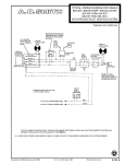
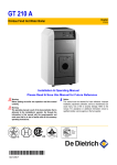
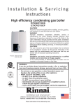
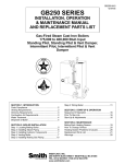
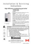
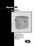
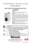
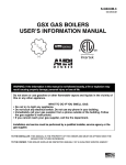
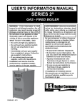
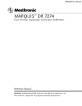
GVXUM-1
00-GVXUM
GVX GAS BOILERS
USER’S INFORMATION MANUAL
WARNING: If the information in this manual is not followed exactly, a fire or explosion may
result causing property damage, personal injury or loss of life.
Do not store or use gasoline or other flammable vapors and liquids in the vicinity of
this or any other appliance.
WHAT TO DO IF YOU SMELL GAS:
• Do not try to light any appliance.
• Do not touch any electrical switch. Do not use any phone in your building.
• Immediately call your gas supplier from a neighbor’s phone. Follow the gas
supplier’s instructions.
• If you cannot reach your gas supplier, call the fire department.
Installation and service must be performed by a qualified installer, service agency or the
gas supplier.
TO THE INSTALLER: THIS MANUAL IS THE PROPERTY OF THE OWNER AND MUST BE AFFIXED NEAR THE
BOILER FOR FUTURE REFERENCE.
TO THE OWNER: THIS BOILER SHOULD BE INSPECTED ANNUALLY BY A QUALIFIED SERVICE AGENCY.
PAGE 2
HVX USER’S INFORMATION MANUAL
BASIC OPERATION
WARNING
Service on this boiler should be undertaken
only by trained and skilled personnel from a
qualified service agency.
CAUTION
Should overheating
to shut off, do not
electrical supply to
the gas supply at
appliance.
occur or the gas supply fail
turn off or disconnect the
the pump. Instead, shut off
a location external to the
Do not use this boiler if any part has been under
water. Immediately call a qualified service
agency to inspect the boiler and to replace any
part of the control system and any gas control
which has been under water.
A. General. This water boiler is an induced draft
appliance and is equipped with controls for proper
operation. All controls must be in proper working
order. Contact a qualified service agency to provide
annual maintenance as specified in Installation,
Operation and Maintenance Manual.
1. Limit. See Figure 1. A device which automatically interrupts boiler operation when the water
temperature exceeds the set point. Maximum
allowable temperature is 220°F (104°C).
Original equipment with this boiler is a
Honeywell L4080B1253. Boiler operation is
interrupted when system temperature reaches
cut-out temperature. Boiler operation resumes
automatically when system temperature falls
approximately 15°F (8°C) below the cut-out
temperature.
2. Flame Rollout Switch. See Figure 1. A device
which automatically interrupts boiler operation
when flames or excessive heat are present in
the combustion area. The control is a single use
device. If the control is activated to interrupt
boiler operation, do not attempt to place boiler in
operation. Contact a qualified service agency.
3. Pressure Switch. See Figure 1. A device which
automatically interrupts boiler operation when
there is excessive blockage in the vent system
or fan motor does not operate. This control is an
automatic reset device. If control is activated to
interrupt boiler operation, do not attempt to
place boiler in operation. Contact a qualified
service agency.
4. Pilot. The pilot provides the ignition source for
the main burners. Your boiler has an intermittent
pilot. The intermittent pilot ignites only when
there is a call for heat and extinguishes when
the call for heat ends. See Figure 5.
5. Gas Valve. The gas valve monitors pilot flame
and regulates gas flow to the burners and pilot.
See Figure 1.
6. Safety Relief Valve. A device which protects
the boiler against excessive pressure. The safety relief valve can discharge a large amount of
hot water - the installer should provide piping
to discharge water near floor at a floor drain.
See Figures 2 and 3. If the safety relief valve
discharges water, follow instructions TO TURN
OFF GAS TO APPLIANCE (see Figure 4), and
contact a qualified service agency.
B. Instructions to place boiler in operation and to turn
off the boiler are shown on the Operating Instruction
Label posted on the inner jacket panel of the boiler.
The instructions are also shown in Figure 4.
C. Sequence of Operation.
1. Thermostat calls for heat, energizes circulator.
2. Limit senses boiler water temperature. Prevents
operation until water temperature falls approximately 15°F (8°C) below the cut-out temperature.
3. Fan energizes.
4. Gas valve energizes.
a. Igniter on.
b. Pilot gas on, igniting pilot.
5. Pilot flame detected.
a. Igniter off.
b. Main gas on, igniting main burners.
Note: If pilot flame is not detected within 30
seconds, the igniter is turned off for 30 seconds,
and then turned back on. If the pilot is not
detected within 30 seconds, the igniter and pilot
gas are turned off for 5 minutes. The sequence
then resumes at Step 4a.
6. Call for heat ends.
Pilot and main gas off, extinguishing pilot and
main burners.
If this sequence is not followed exactly, follow
instructions TO TURN OFF GAS TO APPLIANCE
(see Figure 4) and contact a qualified service
agency.
HVX USER’S INFORMATION MANUAL
Figure 1: Control Locations
Figure 2: Safety Relief Valve Hook-Up Installation
with Air Elimination in System Piping
Figure 3: Safety Relief Valve Hook-Up
with Air Elimination
PAGE 3
PAGE 4
HVX USER’S INFORMATION MANUAL
Figure 4: Intermittent Ignition Operating Instructions
HVX USER’S INFORMATION MANUAL
PAGE 5
USER MAINTENANCE
WARNING
Product Safety Information
Refractory Ceramic Fiber Product
This appliance contains materials made from
refractory ceramic fibers (RCF). Airborne RCF,
when inhaled, have been classified by the
International Agency for Research on Cancer
(IARC), as a possible carcinogen to humans.
After the RCF materials have been exposed to
temperatures above 1800°F (980°C), they can
change into crystalline silica, which has been
classified by the IARC as carcinogenic to
humans. If particles become airborne during
service or repair, inhalation of these particles
may be hazardous to your health.
Avoid Breathing Fiber Particulates and Dust
Suppliers of RCF recommend the following
precautions be taken when handling these
materials:
Precautionary Measures:
Provide adequate ventilation.
Wear a NIOSH/MSHA approved respirator.
Wear long sleeved, loose fitting clothing and
gloves to prevent skin contact.
Wear eye goggles.
Minimize airborne dust prior to handling and
removal by water misting the material and
avoiding unnecessary disturbance of
materials.
Wash work clothes separately from others.
Rinse washer thoroughly after use.
Discard RCF materials by sealing in an airtight
plastic bag.
First Aid Procedures:
Inhalation: If breathing difficulty or irritation
occurs, move to a location with fresh clean air.
Seek immediate medical attention if symptoms
persist.
Skin Contact: Wash affected area gently with a
mild soap and warm water. Seek immediate
medical attention if irritation persists.
Eye Contact: Flush eyes with water for 15 minutes while holding eyelids apart. Do not rub
eyes. Seek immediate medical attention if irritation persists.
Ingestion: Drink 1 to 2 glasses of water. Do not
induce vomiting. Seek immediate medical
attention.
WARNING
Service on this boiler should be undertaken only
by trained and skilled personnel from a qualified
service agency. Inspections should be performed at intervals specified in the Installation,
Operation and Maintenance Manual and this
User’s Information Manual. Maintain manuals in
a legible condition.
Keep boiler area clear and free of combustible
materials, gasoline and other flammable vapors
and liquids.
Do not place any obstructions in boiler room that
will hinder flow of combustion and ventilation
air.
A. General Housekeeping (Continuous).
1. Keep boiler area clear and free of combustible
materials and obstructions to the free flow of
combustion and ventilation air to the boiler.
2. Do not store or use gasoline or other flammable
vapors or liquids in the vicinity of the boiler or
any other appliance.
3. Do not store or use sources of hydrocarbons in
the vicinity of the boiler. Sources of hydrocarbons include bleaches, cleaners, chemicals,
sprays, paint removers, fabric softeners and
refrigerants.
4. Check Safety Relief Valve for water leakage. If
leakage exists, contact a qualified service
agency.
B. Inspect Vent System (Monthly): Vent pipe must
be sealed with no separations, obstructions, or
sags.
CAUTION
Vent system operates under positive pressure
when venting horizontally or vertically with 3"
diameter AL294C vent. Leakage in vent system
will spill products of combustion into building.
Severe vent system leakage can cause carbon
monoxide poisoning.
PAGE 6
HVX USER’S INFORMATION MANUAL
C. Inspect Pilot and Main Burner Flames (Monthly).
1. Remove Front Jacket Panel by lifting and
pulling out.
2. Adjust thermostat to lowest setting.
3. Loosen screws at Burner Observation Cover,
located on base, just above main burners and
remove cover by lifting.
CAUTION
Burner Observation Cover may be hot!
4. Adjust thermostat to highest setting. Verify
operation follows Section C, Sequence of
Operation, of this manual.
5. View flames through observation port.
6. Check pilot flame. See Figure 5. The pilot flame
should be medium blue covering approximately
³⁄₈" to ¹⁄₂" (10 to 12 mm) of the sensing probe. If
the flame is yellow and lazy, follow instructions
TO TURN OFF GAS TO APPLIANCE (see
Figure 4), and contact qualified service agency.
7. Check main burner flames. See Figure 5. The
flames should have clearly defined inner cones
approximately 1½" (40 mm) high and should
have a very sharp blue color characteristic. If
the flame is yellow and lazy, follow instructions
TO TURN OFF GAS TO APPLIANCE (see
Figure 4), and contact qualified service agency.
8. Adjust all thermostats to lowest setting to shut
down boiler.
9. Replace Burner Observation Cover and Front
Jacket Panel.
10. Adjust thermostats to normal setting.
D. Controls (as required by control manufacturer)1.
1. Safety Relief Valve. Conduct try lever test as
outlined in manufacturer’s instruction tag on the
safety relief valve.
2. Low Water Cut-off (if used). Follow instructions
provided by control manufacturer.
E. General Inspection and Maintenance (Annual).
For continued safe operation a qualified service
agency must provide a more detailed inspection of
burners, heat exchanger and vent system, and provide maintenance as specified in the Installation,
Operation and Maintenance Manual.
Figure 5: Pilot and Main Burner and Flames
Controls maintenance may be part of annual inspection and maintenance by a qualified service agency if annual frequency is
xspecified by controls manufacturer.
1
HVX USER’S INFORMATION MANUAL
PAGE 7
WESTCAST, INC.
260 NORTH ELM STREET • WESTFIELD, MA 01085
TEL. (413) 562-9631 FAX (413) 562-3799
www.smithboiler.com