1
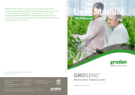
professional horticultural sector. Based on Precision Growing principles, these solutions are particularly applied to the cultivation of vegetables and flowers. In addition to its stone wool substrates, GRODAN also provides tailor-made advice and tools to support Precision Growing and thus facilitate the sustainable production of healthy, safe and tasty fresh produce for consumers. More information on the GroSens System can be found at www.grodan.com/grosens Rockwool BV - trading as Grodan T +31 (0)475 35 30 20 Industrieweg 15 F +31 (0)475 35 37 16 www.linkedin.com/company/grodan 6045 JG Roermond [email protected] www.twitter.com/grodan P.O. Box 1160, 6040 KD Roermond www.grodan.com www.3xsustainable.com The Netherlands GRODAN is a registered trademark of ROCKWOOL INTERNATIONAL A/S. GroSens is a registred trademark of Rockwool International AS. © ROCKWOOL B.V. GRODAN 2015 All rights reserved. 12 All our information and advice is compiled with the greatest possible care and in accordance with state of the art technology. However we are unable to assume any liability for the contents. – September 2015 GRODAN supplies innovative, sustainable stone wool substrate solutions for the Installation Manual MultiSensor GROSENS ® Makes precision irrigation possible www.grodan.com/grosens Table of contents 1Introduction 4 1.1 Before installation 4 1.2 Installation steps 5 2 Hardware installation 6 2.1 General 6 2.2 6 Connecting first set of cables 2.3 Smartbox 7 2.4 Connecting second set of cables 7 2.5 GroSens Sensors 8 2.6 How to install the Sensors in the greenhouse 9 2.7 Setting the correct plate height 9 3 Software installation Smartbox 10 3.1 General 10 3.2 Login 10 3.3Devices section 11 3.4 11 Irrigation section and Sensors 3.5Other devices 12 3.6 Create new section 12 3.7 Section settings 12 3.8 Slab types – setting the correct slab type 13 3.9 Monitoring - adding and configuring Sensors 15 3.9.1 Adding Sensors 15 3.9.2 Row and offset – configuring a Sensor 16 3.10 Sunrise/sunset and lighting setup 16 3.11 System date, time and time zone 17 3.12 Update 18 3.13 Manage users – authorisation levels 18 4 Connection to climate computer 19 4.1 Hardware installation 19 4.2 Software installation 20 4.3 Converter settings 20 5Troubleshooting 21 6Maintenance 21 7 Range and accuracy 21 8Warranty 22 9Appendices 22 9.1 Sensor 22 9.2 Reader 23 9.3 Receiver 23 9.4 GroSens Smartbox 24 9.5 Convertor (climate computer analogue interface) 25 9.6Overview of standard GroSens System 26 9.7 28 Radio Frequency - declaration of Conformity www.grodan.com 1 Introduction ▸ Greenhouse environment ◂ ▸ Climate computer cabinet ◂ ▸ Monitoring ◂ Remote access via Internet Browser GroSens Receiver GroSens Extender 1x PoE Injector 1x Network switch Computer 1x This manual will guide you through the installation of the Grodan GroSens GroSens Convertor System. The GroSens System consists of several separate components: 1x • GroSens Sensors GroSens Sensors GroSens Reader • GroSens Receiver Climate computer software package • GroSens Reader GroSens Smartbox • GroSens Smartbox Climate computer P1 P2 P3 - % WC - % WC WC% drain start stop sunrise start sunset • GroSens Convertor P1 P2 P3 - % WC • Ethernet Extender (if required) sunrise - % WC WC% start drain sunrise stop start sunset sunrise resaturate refreshment false drain • Power over Ethernet (PoE) injector 3x 1x All elements of a standard GroSens System 1x are described in appendix 8.6. 1.1 Before installation Installation 1.2 Installation steps For a fast installation of the GroSens System, make sure the • Enough UTP Ethernet cable (Cat. 5e) to connect the The following steps need to be completed to install a GroSens Receiver and GroSens Smartbox. GroSens System successfully: following items are in place: • IT • An extra LAN (Local Area Network) that can be used for the GroSens System. This LAN needs to be separate from the climate computer LAN. • • There should be 3-6 free electricity sockets available Ethernet cable (3x) for the PoE injector, Smartbox, and Convertor 1. Hardware installation: Described in section 2 Adapter (3x) (the Convertor can also be powered with 24 V from 2. Software installation: Described in section 3 the climate computer cabinet). 3. Connection to climate computer: Described in section 4 Ethernet UTP cable CAT5, 5e or 6 (not included) 3 free analogue connections to the climate computer. Analogue cable 3 to 6 connections on the LAN, each with its own The GroSens System will communicate 3 separate The different components and the connections between IP address. signals: WC, EC and Temperature. These signals them are shown in the figure above. The numbers in are 0-5 Volt signals. In case this is not available or parentheses show the number of these components in a unknown, contact the climate computer supplier. standard GroSens System package. • Legenda There must be a LAN (Ethernet) connection in the climate computer cabinet. 4 5 www.grodan.com 2 Hardware installation 2.3 Smartbox After connecting all cables and powering on the GroSens Smartbox, the Smartbox LCD should immediately display 2.1 General The hardware must be installed in the following order: Before starting to install the system, the rough location “Loading…”. After about 50 seconds, the LCD should switch to a screen that displays the GroSens Smartbox IP address of the GroSens Sensors should be defined. The maximum 1.Connect first set of cables (Section 2.2) assigned by the router, the Smartbox identity (initially set to distance from the GroSens Sensors to the GroSens a.GroSens Smartbox & Network Switch its serial number) and the current (Los Angeles) time. Make a Receiver is 50 meters. Due to the growth of the crop, this b.Network Switch & PoE Injector note of the IP address – it will be important for the next steps. distance will be larger at the start of the season than at the end. The Sensors that are in the same irrigation section 2.Connect power to GroSens Smartbox (Section 2.3) Please note: It is not necessary to plug in a keyboard and should be used to calculate the average of that section. 3.Connect second set of cables (Section 2.4) monitor to the Smartbox for installation. The option is avai- As shown in the overview, the GroSens Smartbox, GroSens a.GroSens Receiver & PoE Injector (including GroSens lable but only for repair purposes. In that case, the GroSens Receiver and GroSens Convertor need to be connected to Ethernet Extender if required) Smartbox works best with a VGA monitor. GroSens Smartbox the LAN. Most growers also have a specific climate com puter digital network, operating with similar Ethernet 4.Activate Sensors (Section 2.5) 2.4 Connecting second set of cables cables. Do not connect the GroSens System to this network. The power supplies must be connected to the 110-230 V~ net with the appropriate plugs. Please note: Ensure that conditions are dry when installing Option 1 the various parts at the locations. Preferably do not install in As shown in the overview, all the provided adapters direct sunlight or in a very hot place. PoE Injector GroSens Receiver should be outside the greenhouse and connected to the appropriate device. 2.2 Connecting first set of cables 100m The GroSens Smartbox should be connected to the Network Switch. From the Network Switch, a second cable is required to the PoE injector. The Ethernet cables provided can be used for both connections. Provide power to the PoE injector if required. GroSens Smartbox Network switch PoE Injector Option 2 Extender PoE Injector GroSens Receiver 100m 100m As alternative to the extender, also a switchbox can be Please note: For a swichbox a power socket is needed. used every 100 meter. In case of a switchbox, the PoE connection of the Receiver should be placed after the switchbox. At that connection This is specially recommended if: point 2 power sockets are needed. • there is already internet available in the Grenhouse • more than 2 extenders/amplifiers are needed to cover larger distances. 6 A Switchbox is not included in the package but can be optained at a local IT/computer store. 7 www.grodan.com First, the long cable into the greenhouse should be con- When the GroSens Receiver is connected to the PoE After activation, both LEDs will light up and, after a few nected to the Receiver. The correct RJ45 outlet must be Injector, two LEDs should light up: the Power LED and Link minutes, only the green LED will glow: used when connecting the PoE injector to the GroSens LED. The Power LED will light up immediately. The link • Receiver. The outlet is located inside the GroSens Receiver LED will turn on as soon as the GroSens Receiver has auto- housing (see below). discovered the GroSens Smartbox; this can take several TEST button LED’s The green LED indicates round-trip communication with the GroSens Smartbox. • minutes. Wait until the Link LED is lit before continuing the The red LED indicates a problem communicating with the GroSens Smartbox. installation process. After the connection is made, 5. You will not need to change GroSens Sensor settings the housing can be closed. LED’s GroSens Receiver Please note: The GroSens Sensors are delivered with 4 fully for installation. The settings can be changed with the charged AA batteries installed. The Sensors are in “hiber- GroSens Reader if needed: nate” mode when delivered. Pressing the TEST button will - Select your network (i.e. System Identity) activate them. It is recommended not to activate them - Go to the Device screen before installation, as the batteries will lose their charge. - Press the TEST button on the Sensor - Select the Sensor in the list. It is best to locate the GroSens Receiver above the highest point of the crop (at the end of the season). Position the 2.6 How to install the Sensors in the greenhouse The cable between the PoE injector outside the green- Sensors in the centre of the area and, for better wireless re- Place a Sensor 8 – 10 cm left from the 2nd block from house and the Receiver inside the greenhouse cannot be ception, as far as possible from steel poles or other heavy the drain hole. The antenna should be placed furthest longer than 100 metres (see option 1). Standard Ethernet greenhouse structures. Fasten the Receiver with a tie-wrap away from the 2nd block. This can be found in drawings cables: Cat5e is sufficient. or another sort of easily removable mounting device in on the right.. case the Receiver needs to be relocated if the GroSens If the distance between the PoE injector and the Receiver Sensors get out of range. In case the cropping system is different and the for- is greater than 100 meters, an Extender or Switchbox must mer mentioned rule cannot be applied, please contact be installed after every 100 metres of cable (see option 2). Please note: You must install the GroSens Smartbox first, There is one Extender provided in the set. The maximum as indicated in the installation sequence. The GroSens distance from the PoE Injector to the Receiver is 200 metres. Receiver will only connect to a GroSens Smartbox that is Extra Extenders to extend the maximum distance can be already running. The Receiver requires 24V of power. ordered from GRODAN Customer Service if required. This can also be realised by using a standard 24V adaptor. Grodan Customer Service. The adapter should output DC voltage between 12-30 2.7 Setting the correct plate height volts, capable of supplying 500 milliamps of current. For all slabs with a height of 7,5 cm: For all slabs with a height of 10 cm: • The guiding plate should be positioned in the lowest • The guiding plate should be positioned in the position. This is the position the Sensors are normally 2.5 GroSens Sensors upper position. See picture: delivered to customers. See picture: The GroSens Sensors need to be positioned within a 50 metre radius of the GroSens Receiver. The following steps should be taken: 1. Determine roughly the spot where the GroSens Sensors need to be placed. 2. Perform a set of measurements with the GroSens Reader close to the chosen spot. See the GroSens Reader manual for more instructions. 3. Determine a representative location and place a GroSens Sensor. 4. Activate the GroSens Sensor by pushing the TEST button. GroSens Sensors 8 9 www.grodan.com 3 Software installation Smartbox 3.3 Devices section (shortcut button ) The devices overview shows how your Grosens System is configured in the greenhouse in 3.1 General a non-graphical format. It also tells you how the complete systems are operating. All hardware is preinstalled with the standard software necessary. This section highlights the steps necessary to The information from the Sensors is displayed in table apply custom settings. format, grouped by irrigation section. The information from the Reader, Converters and Receivers is grouped in a 3.2 Login separate section. If all bullets are green or yellow, Log in with a computer plugged into the router or everything is working fine. If a red bullet is shown, the connected to the network switch with an ethernet cable. device does not work and action is needed. Go to the IP address listed on the Smartbox LCD screen (e.g. http://192.168.1.58/). 3.4 Irrigation section and Sensors It takes about 20 seconds to load the login screen. On the start page, your preferred language can be set using the drop down menu in the top right-hand corner. Access to the GroSens Smartbox is protected with a username and password. Usernames and passwords are created at installation. Clicking the “log in” button will redirect you to the “dashboard page” or “starting page”. Field/Function Description Clicking the section name takes you to the graph of that section (see Chapter 3 User Manual). Clicking the cogwheel takes you to the section settings (see Chapter 4 User Manual). The Status section provides information about device errors: - A green dot is shown if data from the GroSens Sensor has been received by the GroSens Smartbox. - A yellow triangle is shown if the Sensor has not delivered data in the last 10 minutes. - A red icon is shown if the device is not working or not connected. - The battery icon indicates the Sensor battery status: - green: ok - yellow: less than 30% capacity – it is advisable to replace the batteries - red: you should replace the batteries immediately as no data is being received - Signal strength icon: - green: Sensor is working ok - yellow: Sensor is working but it is advisable to move it closer to the Receiver or you might lose the connection - red: signal strength is low – move the Sensor closer to the Receiver. Data might not be received because the Sensor is too far from the Receiver This column displays the name of the GroSens Sensor. Clicking the Sensor number takes you to the section, where you can enter a row and offset for this Sensor. WC, EC, T If you use a valid email address to create a user, dont forget to set the notification level at none! this can be done in the manage users function (see 5.2.2) 10 These columns show the latest values received from the GroSens Sensor. Clicking any of the values takes you to the detailed chart for that Sensor. This column displays whether the data from the GroSens Sensor has been used to calculate the average WC, EC and T for the section. This shows the date and time when the values from the GroSens Sensor were last checked and updated. 11 www.grodan.com Field/Function Description Section name Enter the name for this section Media type Choose the correct slab type for this section via the drop down menu. Make sure it is configured correctly – see 5.1.3. Cancel If you click “Cancel”, section creation will be aborted. Apply Saves the settings. Delete Section - A green dot is shown if the data from the GroSens Sensor has been received by the GroSens Smartbox. If you are configuring an existing section, e.g. section A, the “Delete” button will appear. This will enable you to delete a section. - A yellow triangle is shown if the device has not delivered data in the last 10 minutes. Be aware that all the information will be lost. 3.5 Other devices Field/Function Description Clicking the cogwheel takes you to the section settings (see Chapter 4 User Manual). The Status section provides information about device errors: - A red icon is shown if the device is not working or not connected. This column displays the name and serial number of the GroSens device. - CO is a Converter - HE is a HandHeld - RE is a Receiver This column displays the type of device: Reader, Receiver or Converter This column displays the device’s IP address (n/a = not applicable). 3.8 Slab types – setting the correct slab type In this menu you can configure the slab type that applies to your greenhouse. The correct slab determines the proper calculation model. This shows the date and time when the values from the GroSens devices were last checked and updated. When you click “Slab Types”, the following window will appear: 3.6 Create new section Click “Add” to go to the next screen. This function allows you to create and configure an • Section Settings irrigation section in which Sensors can be placed. When • Monitoring you select this function, the following picture will appear - Add Sensor and display the section settings. There are three - Select Sensor sub-screens to complete: - Row and Offset – configure a Sensor Field/Function Description • Irrigation Control – connect a Converter Name Give the slab a name such as “Section 1”, “Location 1” or “2016 season”. Copy From Select the appropriate slab type from the dropdown menu: Apply Click “Apply” to save the settings. 3.7 Section settings Here you can give the section a name and choose the proper slab type or media type. Make sure the slab type is correctly configured – this is described in section 3.8. Important! Click “Apply” to save the settings. 12 13 www.grodan.com You will be taken back to the main screen, where your After clicking “Apply”, you will see a summary of the designed slab can be found in the menu bar. Click your configured slab type: named slab type and then “Edit”. This will take you to a menu bar where you can enter the correct settings the settings. Field/Function Description Length You can select the appropriate length from the dropdown list: 3.9 Monitoring - adding and configuring Sensors 3.9.1 Adding Sensors When you click “Monitoring”, the window shown right will appear. Width You can select the appropriate width from the dropdown list: Height You can select the appropriate height from the dropdown list: Brand Confirm the brand from the dropdown list: Field/Function Description Add Sensor Clicking this dropdown menu opens a list of all the Sensors connected to the system along with their sections. You can select a Sensor by clicking its number. After selecting a Sensor it will appear in the section Row This is the row in which the GroSens Sensor is located. If the field is is blank, you can enter a number. Offset This shows the post in the row where the GroSens Sensor is located. If the field is blank, you can enter a number. Clicking the cross deletes a Sensor from that section and takes you back to the pool. It may take 20 seconds for it to appear in the pool. Crop Type Select the crop type from the dropdown list: Pepper Spacer If you use a “pepper spacer” please check the appropriate spacer: Apply Click “Apply” to save the settings. 14 Cancel If you click “Cancel”, section creation will be aborted. Apply Saves the settings. 15 www.grodan.com 3.9.2 Row and offset – configuring a Sensor Field/Function Description When you click the row or offset number in the screen, Natural Lighting Check this option if you are using natural lighting. you will see the following window which allows you to Latitude Shows the latitude. Longitude Shows the longitude. Get Latitude Longitude When you click this function, you will be taken to Google Maps to help you find the appropriate latitude and longitude. You can copy and paste the values into this page. Artificial Lighting Check this option if you are using artificial lighting. Lights on time Time when lights go on. Lights off time Time when lights go off. Apply Click “Apply” to save the new values. configure a Sensor: Field/Function Description Row This is the row in which the GroSens Sensor is located. If this field is blank, you can enter a number. Offset This is the post in the row where the GroSens Sensor is located. If this field is blank, you can enter a number. Operation mode When you click this function, a dropdown menu will appear. The Sensor is set to normal mode. Cancel If you click “Cancel”, section creation will be aborted. Apply Saves the settings. Alerts Clicking this button opens a window which gives you detailed information on recent alerts. Clicking the dashboard icon ( ) returns you to the dashboard. 3.11 System date, time and time zone Delete Device Activating the delete function completely removes the Sensor from the Smartbox System. After deleting you can restore the Sensor by clicking the test button. 3.10 Sunrise/sunset and lighting setup In this menu you can select whether you use artificial or natural lighting: • For natural light, you will need to enter the longitude and latitude to display sunrise and sunset in the graphs (yellow blocks and time). Data is gathered every 3 minutes during daylight hours and every 30 minutes during the night. • When artificial light is chosen, lighting time intervals can be set. During the set lighting time period, data Field/Function Description will be gathered every 3 minutes. Time Zone The time zone where the GroSens System is located. Use Internet Time Use internet time as default (highly recommended). Date Current date. Time Current time. Update Click “Update” to save the new values. 16 17 www.grodan.com 4 Connection to climate computer 3.12 Update When you click this function, the system will check whether there are any software updates available. 4.1 Hardware Installation GroSens Convertor Output 1. The GroSens Convertor has the following outputs: Check whether the climate computer has 3 free analogue connection points. If they are available, proceed with further installation. If not, contact the climate computer installer. WC Water Content (WC) 0-5V output representing average water content of the section EC Electric Conductivity (EC) 0-5V output representing average electrical conductivity of the section TEMP Temperature (Temp) 0-5V output representing average temperature of the section 3.13 Manage users – authorisation levels In this section you can add extra usernames and passwords 2. The GroSens Convertor needs to be connected to the so other employees can have access to the Smartbox Network Switch and climate computer. A cable is sup- System. You can also set the user level. plied for the connection between the Convertor and the Network Switch. Note: the notification level should be set to “None”. 3. For the connection between the GroSens Convertor and Field/Function Description Enter email address Specify the username in this field in the form of an email address. User Password Enter the password in this field. Verify password Verify the password by entering it again. the climate computer, a simple wire cable can be used. Network switch GroSens Convertor Climate computer P1 P2 P3 - % WC - % WC WC% start drain stop sunrise Notification level start sunset sunrise Notification level should be set at “None”. If you select “All”, all alerts are sent to your email address P1 P2 P3 - % WC - % WC WC% start sunrise drain stop start sunset sunrise resaturate refreshment false drain User Level You can choose between “Read Only” – this will only enable you to view the graphs – or “Administrator”. In the administrator role you have access to all menus in the software. 4. The Convertor can be powered on after connection and checking the other parts of the GroSens set. Op tionally, the Convertor can also be fed with 24V from Create User Clicking “Create User” saves the settings for the defined new user. Modify User Clicking “Modify” after a defined user enables you to modify the settings, including the password. You can also remove a previously defined user. the climate computer cabinet in which it is installed. 5. The Convertor has a flexible mounting bracket. It will simply snap onto a standard-sized DIN rail found in many climate computer enclosures. Alternatively, the bracket can be mounted with screws directly to a wall with the Convertor then clipped onto the mounting bracket. 6. The labelled ports on the Convertor: ‘WC’, ‘EC’ and ‘Temp’ should be connected to the climate computer. 18 19 www.grodan.com 5 Troubleshooting 4.2 Software installation After following the procedure for the hardware installation of the Convertor and when the Link LED is constantly lit, the following steps need to be completed: If no graph is visible on the web user interface or climate In the event that the Link LED is not lit on the Convertor, computer, try the following: try the following: • • 1. Click on the cog wheel of the section, the connvertor should be assigned to 2. Click “irrigation settings” • 3. Irrigation control – connecting a Converter Check the status LEDs of all GroSens devices. Review On the GroSens Convertor is a Reset button. Press and the installation procedure of hardware and software if hold this button for 5 seconds. If this doesn’t fix the a red LED is lit. issue, press and hold the Restore button on the Con- Check the GroSens System parts. This can be done vertor for 5 seconds. This will restore the Convertor to in the “Grower settings - overview” screen in the web factory settings. Clicking the “Irrigation Control” tab takes you to the user interface (see Sections 3.3., 3.4 and 3.5). All status following window, in which you can configure a icons need to be green and data should be refreshed If these actions or checks do not fix the issue, please don’t every 3 minutes. hesitate to contact GRODAN. Converter: • Check whether the GroSens devices are visible in the network with an IP-scan program. If no devices can be found, restart the GroSens Smartbox (see Section 8.4). Field/Function Description Required Irrigation Supply For future use, in development Converter If you click the dropdown menu, the following screen will appear with connected Converters. Select the Converter you want to attach to this section from the list. Irrigation Priority For future use, in development the exception of software updates via the Internet. Updates Cancel If you click “Cancel”, section creation will be aborted. can be installed automatically by clicking on the “Grower Apply Saves the settings. 6 Maintenance The GroSens System requires no special maintenance, with settings - check for update” option in the installation menu (see Section 3.5). Now the GroSens Convertor can receive commands from the GroSens Smartbox and send the analogue information Calibration of the GroSens Sensors is not required. to the Climate Computer. Each Sensor has 4 AA batteries. The storage level of the batteries is shown in the installation status screen of all Sensors. 4. As a last step, it is important to check the values in the TEST button LED’s Climate Computer. The values should be identical to the GroSens Smartbox. If the values are different, the A warning is displayed before the battery level goes under voltage needs to be checked. the lower limit. You will normally have to change the batteries once a year before the start of a new crop. 5. If different settings in voltage are needed due to different voltage settings of the climate computer, go to “Converter settings” in the menu settings 7 Range and accuracy 4.3 Converter settings The Converter settings are configured as described below. They can be edited if necessary by entering the required values. Click “Apply” to save your settings. The GroSens System measures Water Content (WC), Type Range Accuracy Resolution Electric Conductivity (EC) and Temperature (Temp). Water Content (WC) 0-100% V/v 5% V/V 0.1% V/V If you have edited values and you want to reset the original The table on the right provides accuracy information of figures, click “Load original settings”. the GroSens Sensor. Electric Conductivity (EC) 0-10 mS/cm 0.5 mS/cm 0.01 mS/cm For more information on how to use the system and soft- The accuracy decreases slowly towards the borders of the 0-50°C 1°C 0.05°C ware functionalities, please read the GroSens user manual. respective ranges and is not guaranteed outside them. Temperature (Temp) 20 21 www.grodan.com 8 Warranty 9.2Reader GroSens Reader The GroSens Reader has the following functions: 1. It adjusts Sensor and Section settings. For Warranty information, please contact our 2. It displays WC, EC and T measurements from a Customer Service Departments. GroSens Sensor. 3. It tests the wireless connectivity of a Receiver For US and Canada: For other countries contact the head office: Roxul Inc. - GRODAN Rockwool BV - GRODAN 8024 Esquesing Line Industrieweg 15 5045 JG Roermondthe Netherlands Milton ON L9T 6W3 Phone : (31) 475 353 020 Canada Phone : (1) 905 636 0611 email: [email protected] or a Sensor. www.grodan.com 9 Appendices Handheld device 9.1 Sensor GroSens Sensor The GroSens Sensors have two functions: 1x 1. They perform measurements in the slab at a regular time interval. To determine the right measurement location of the Sensor, see Section 3.4. 2. They send the measured data wirelessly to the GroSens Receiver. The Sensor automatically searches for 9.3 Receiver a connection to a Receiver. No settings are needed The GroSens Receiver has one function: here. The wireless frequency depends on where you 1. It controls wireless dataflow between the GroSens GroSens Receiver Sensors and the GroSens Smartbox. are in the world. LED’s The Sensor is equipped with: • A green LED that blinks briefly every minute when in • A red LED that is lit when there is no communication. • TEST button: In the case of a poor or lost connection, full operation and all conditions are satisfactory. push the TEST button once. The Sensor will start searching • for a Receiver again until a connection is established. The GroSens Receiver is equipped with two LEDs: The GroSens Sensor is rated at IP65 and is built with • The Power LED indicates if the Receiver is powered. protected boards (EMC). • The Link LED indicates whether the Receiver is connected to the GroSens Smartbox. In the stone wool slab 3x Centrally positioned in the greenhouse 1x 22 23 www.grodan.com 9.4Smartbox 9.5 Convertor (climate computer analogue interface) GroSens Smartbox The GroSens Smartbox is a small computer that has the GroSens Convertor The GroSens Convertor has one task: 1. It translates the data from multiple GroSens Sensors following tasks: to the climate computer’s analogue input module. 1. It connects to the GroSens Receiver over Ethernet to The Convertor can be connected to any type of climate gather the measured data. computer that can receive 0-5V input. Otherwise, please 2. It stores the data and maintains a log of all GroSens consult your climate computer supplier for advice. devices connected to the LAN. 3. It translates the raw measurements into figures. 4. It creates averages of GroSens Sensor data over the chosen sections of the greenhouse according to the grower’s wishes. 5. It transmits an alarm if the system devices do not function properly. 6. It stores custom settings to perform necessary calculations. 7. It connects over the Internet to download updates. In between Smartbox and The GroSens Smartbox is equipped with: Close to the climate computer LCD Screen - The Smartbox menu can be accessed by climate computer 1x 1x pressing the button in the lower left-hand corner of the Smartbox front panel: • Shut down – This menu option can be used to ma nually shut down the Smartbox device. This can be useful when transitioning to another Smartbox device, or before storing the Smartbox after the end of the growing season. To shut down the Smartbox, simply press the button next to the checkmark icon on the LCD display. • Restart –The Restart menu option can be found by pressing the bottom-left button again. To restart the Smartbox, simply press the button next to the checkmark icon on the LCD display. • Restore DHCP Network Settings –This option can be used to reset the IP Address, Gateway, and Netmask to their default values assigned by your router. This can be beneficial if the Smartbox cannot connect to the network. To restore the default network settings, press the button next to the checkmark icon () on the LCD display. Please note: Using DHCP settings is recommended. • Enable VPN – A VPN (Virtual Private Network) can be used to enable technical support personnel to inspect and repair any issues that may arise with the GroSens System. To enable a VPN, press the checkmark button. To disable the VPN, press the button next to the ‘X’ on the LCD display. • Version Number – This displays the current version of the Smartbox software. 24 25 www.grodan.com GroSens Sensor (wireless) 9.6 Overview of standard GroSens System The Sensors give an extremely accurate measurement of WC, EC and temperature in the stone wool substrate. GroSens Convertor The Converter converts the digital information in the Smartbox to analogue output. This makes the GroSens System connectable to most climate-control systems. GroSens Smartbox The Smartbox processes the data from the Sensors, taking the slab type and dimension into account. The WC, EC and temperature mea- 1x surements are transmitted to the climate-control computer and can 3x be viewed on any external com puter connected to the grower’s Internet / Ethernet site. 1x 1x 1x GroSens Reader GroSens Receiver The Reader enables easy installation and can also be used as The Receiver picks up the signals a HandHeld device to quickly from the Sensors. get figures from a GroSens Sensor as you walk through the greenhouse. The GroSens System, -Smartbox, -Sensor and Sensor design, are patented technologies. 26 27 www.grodan.com 9.7 Radio Frequency - declaration of Conformity Industry Canada Declaration of Conformity European kitt: Europe and Russia This device complies with Industry Canada licence-exempt RSS standard(s). Operation is subject to the following two The GRODAN GroSens wireless sensing system uses license-free radio frequencies to communicate Sensor data. conditions: (1) this device may not cause interference, and (2) this device must accept any interference, including interfe- These wireless devices constitute ‘short range device’ (SRD). rence that may cause undesired operation of the device. Applicable Material Numbers: Le présent appareil est conforme aux CNR d’Industrie Canada applicables aux appareils radio exempts de licence. GroSens Sensor 132253, GroSens Receiver 132256, GroSens Reader 132260, (EUR system) L’exploitation est autorisée aux deux conditions suivantes: (1) l’appareil ne doit pas produire de brouillage, et (2) l’utilisateur de l’appareil doit accepter tout brouillage radioélectrique subi, même si le brouillage est susceptible d’en Operating Frequency Range: 863-870 MHz (868 ISM band) Maximum Output Power: 25 mW (14 dBm) effective radiated power (e.r.p.) Interference Avoidance Technology: Listen Before Talk (LBT) + Automatic Frequency Agility (AFA) compromettre le fonctionnement Contains IC ID: 1846A-XB900HP EC Declaration of Conformity (for Europe and additional locales) C-Tick Declaration of Conformity (for Australia) These products are in conformity with the essential and relevant requirements of the EU Directive 1999/5/EC R&TTE and The devices comply with Radiocommunications (Short Range Devices) Standard 2004. the EU Directive 2011/65/EU RoHS2 ACMA: N30375 Safety: (article 3.1a)EN60950-1:2006+A12:2011, EN 62311:2008 EMC: (article 3.1b) ETSI EN 301 489-1 V1.9.2 (2011-09) in accordance with ETSI EN 301 489-3 V1.4.1 (2002-08) Spectrum: (article 3.2) ETSI EN 300 220-2 V2.3.1 (2010-02) Row-lite kitt (Japan) The GRODAN GroSens wireless sensing system uses license-free radio frequencies to communicate Sensor data. These wireless devices constitute ‘short range device’ (SRD). NA – kitt: North America and Australia The GRODAN GroSens wireless sensing system uses license-free radio frequencies to communicate Sensor data. Applicable Material Numbers: These wireless devices constitute ‘short range device’ (SRD). GroSens Reader 188181, (RoW-Lite system) Applicable Material Numbers: Operating Frequency Range: 2410-2465 MHz (2.4GHz ISM band) Maximum Output Power: 10 mW (10 dBm) effective radiated power (e.r.p.) GroSens Sensor 132254, GroSens Receiver 132258, GroSens Reader 132261, (CAN/USA/AUS system) GroSens Sensor 188180, GroSens Receiver 188179, Interference Avoidance Technology: Direct Sequence of Multiple Channels Operating Frequency Range: 915.6-927.6 MHz (900 MHz ISM band) Maximum Output Power: 250 mW (24 dBm) effective radiated power (e.r.p.) EC Declaration of Conformity (for Europe and additional locales) Interference Avoidance Technology: Frequency Hopping Spread Spectrum (FHSS) These products are in conformity with the essential and relevant requirements of the Directive 2004/108/EC (EMC), Directive 2006/95/EC (LVD) and Council Directive 1999/5/EC R&TTE. EC Declaration of Conformity (for USA) The devices comply with Part 15 of the FCC Rules. Operation is subject to the following two conditions: (i.) this device Safety: (article 3.1a)EN60950-1:2006/A12:2011, EN 62311:2008 may not cause harmful interference and (ii.) this device must accept any interference received, including interference that EMC: (article 3.1b) may cause undesired operation. ETSI EN 301 489-17 V2.1.1 (2009-08) Spectrum: (article 3.2) ETSI EN 301 489-1 V1.8.1 (2008-04) in accordance with ETSI EN 300 328 V1.7.1 (2006-10) Contains FCC ID: MCQ-XB900HP FCC Declaration of Conformity (for USA) The devices comply with Part 15 of the FCC Rules. Operation is subject to the following two conditions: (i.) this device may not cause harmful interference and (ii.) this device must accept any interference received, including interference that may cause undesired operation. Contains FCC ID: OUR-XBEEPRO 28 29 www.grodan.com Industry Canada Declaration of Conformity The devices comply with all applicable requirements of the Industry Canada specifications RSS-210. Notes Contains IC ID: 4214A-XBEEPRO C-Tick Declaration of Conformity (for Australia and New Zealand) The devices comply with Radiocommunications (Short Range Devices) Standard 2004. ACMA: N136, Z1123 Japan Declaration of Conformity The listed products comply with the Technical Regulations Conformity Certification of Specified Radio equipment (ordinance of MPT N° 37,1981). ID:005NYCA0378 Row-kitt: New Zealand and other countries. The GRODAN GroSens wireless sensing system uses license-free radio frequencies to communicate Sensor data. These wireless devices constitute ‘short range device’ (SRD). Applicable Material Numbers: GroSens Sensor 132255, GroSens Receiver 132259, GroSens Reader 132262, (RoW system) Operating Frequency Range: 2410-2465 MHz (2.4GHz ISM band) Maximum Output Power: 63 mW (18 dBm) effective radiated power (e.r.p.) Interference Avoidance Technology: Direct Sequence of Multiple Channels FCC Declaration of Conformity (for USA) The devices comply with Part 15 of the FCC Rules. Operation is subject to the following two conditions: (i.) this device may not cause harmful interference and (ii.) this device must accept any interference received, including interference that may cause undesired operation. Contains FCC ID: OUR-XBEEPRO Industry Canada Declaration of Conformity The devices comply with all applicable requirements of the Industry Canada specifications RSS-210. Contains IC ID: 4214A-XBEEPRO C-Tick Declaration of Conformity (for Australia and New Zealand) The devices comply with Radiocommunications (Short Range Devices) Standard 2004. ACMA: N136, Z1123 30 31 www.grodan.com