1
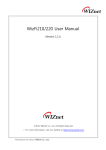
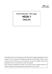
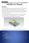
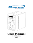
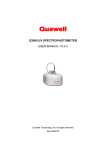
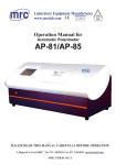
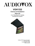
LCD Module User Manual
LCD Module User Manual
MODULE NO.:EPD12864-XX
REV.D
Dalian Good Display Co., Ltd.
TEL.: 86-411-84619565/84573876
FAX.: 86-411-84619585
E-mail: [email protected]
Website: http://www.good-lcd.com
Dalian Good Display Co., Ltd
EPD12864-XX REV.D
(COG-EPD12864)
OCT/2009
PAGE 2 OF 15
DOCUMENT REVISION HISTOR
DOCUMENT
REVISION
FROM
TO
DATE
DESCRIPTION
CHANGED
BY
CHECKED
BY
A 2008.01.21 First Release.
Note: EPD-12864-XX included
EPD-12864-02, -03, -04, -05, -06, -07.
LINDA
ZHU
GAO KE
QIANG
A
B 2008.05.08 Items 1 to 2 were updated.
1.) (Page 10, Table 5) The value of VLCD* was updated.
2.) (Page 12, Table 7) It was updated.
LINDA
ZHU
GAO KE
QIANG
B
C 2008.07.25 Items 1~3 were updated:
JOE
1.)(Page 7, Fig.2)The term ”LCD controller/driver” is
CHEUNG
used.
2.)(Page 10, table 5) Supply voltage VCI and supply
current ICI was added and supply current IDD was
updated.
3.)(Page 12, point 7.3) Temperature Compensation was
updated.
TSANG FU
ON
D 2009.10.22 Items 1~5 were updated:
XIE HU
C
CHEN
YUE
1.) (Page6, Fig.1) “Module Specification” was updated.
2.) (Page8, Fig.3) “Circuit Diagram” was added.
3.) (Page10,Table3) “Environmental Condition” was
updated.
4.) (Page11, Table5) “Typical Electrical Characteristics”
was updated.
5.) (Page13, Table7) “Temperature Compensation” was
updated.
EPD-12864-XX REV.D
(COG-EPD12864)
OCT/2009
PAGE 3 OF 15
CONTENTS
Page No.
1.
TECHNOLOGY DESCRIPTION
4
2.
TYPICAL APPLICATIONS
4
3.
GENERAL DESCRIPTION
4
4.
MECHANICAL SPECIFICATIONS
5
5.
INTERFACE SIGNALS
9
6.
6.1
6.2
ABSOLUTE MAXIMUM RATINGS
ELECTRICAL MAXIMUM RATINGS – FOR IC ONLY
ENVIRONMENTAL CONDITION
10
10
10
7.
7.1
7.2
7.3
ELECTRICAL SPECIFICATIONS
TYPICAL ELECTRICAL CHARACTERISTICS
TIMING SPECIFICATIONS
TEMPERATURE COMPENSATION
11
11
12
13
8.
8.1
8.1.1
8.1.2
OPTICAL CHARACTERISTICS AT 25°C
OPTICAL CHARACETRISTICS DEFINITION
VIEW ANGLE
CONTRAST RATIO
13
14
14
14
9.
LCD COSMETIC CONDITIONS
14
10.
REMARK
15
EPD-12864-XX REV.D
(COG-EPD12864)
OCT/2009
PAGE 4 OF 15
GOOD DISPLAY
Specification
of
LCD Module Type
Model No.: EPD-12864-XX
1.
2.
Technology Description
BCD (Bi-stable Cholesteric Display) is a sunlight readable reflective LCD with extremely low
power consumption characteristics. Due to the non-volatile memory feature of the technology, zero
power is required to retain the image of the display. Energy is only required to change the displayed
image. No backlighting is required, only ambient lighting from the surrounding is required.
Readability when under direct sunlight is excellent and good contrast from viewing at very wide
angles are possible.
Typical Applications
This module is intended for general purpose graphic and character display applications.
Suggested uses include instrumentation, remote control, electronic product or price label, point of
sale display, general purpose indoor or outdoor signage and information display.
3.
General Description
•
Passive matrix bistable cholesteric display, Positive, reflective LCD graphic module
•
Color: Blue & White (EPD-12864-02)
Red & Amber (EPD-12864-03)
Dark Green & Light Green (EPD-12864-04)
Black & Yellow (EPD-12864-05)
Pink & Peach (EPD-12864-06)
Orange & Yellow (EPD-12864-07)
•
Display resolution: 128 x 64 dots
•
Viewing angle: all angles (for inclinations of <70°, CR > 3)
• 4-wires Serial Interface LCD Controller/Drivers.
•
Driving scheme: Special BCD driving scheme
•
Logic voltage: +3.0 V
•
FPC connection
•
The module does not contain polarizer and the customer is recommended to add a UV cut filter
(98% blocking of 380nm and lower spectral components)
•
The module is licensed by Kent Display Systems
EPD-12864-XX REV.D
(COG-EPD12864)
OCT/2009
PAGE 5 OF 15
4.
Mechanical Specifications
The mechanical detail is shown in Fig. 1 and summarized in Table 1 below.
Table 1
Parameter
Outline dimensions
Viewing area
Active area
Display format
Dot size
Dot spacing
Dot pitch for characters
Weight
Specifications
66.0(W) x 43.4(H) x 1.4(D) (Exclude FPC)
66.0(W) x 78.4(H) x 1.4(D) (Include FPC)
61.0(W) x 31.4 (H)
55.025(W) x 27.505(H)
128(Horizontal) x 64(Vertical)
0.415(W) x 0.415(H)
0.015(W) x 0.015(H)
0.43(W) x 0.43(H)
Approx: 9.5
Unit
mm
mm
mm
dots
mm
mm
mm
grams
EPD-12864-XX REV.D
(COG-EPD12864)
OCT/2009
PAGE 6 OF 15
Figure 1: Module Specification
EPD-12864-XX REV.D
(COG-EPD12864)
OCT/2009
PAGE 7 OF 15
Dummy
32
Dummy
128
COG-EPD12864
GRAPHIC LCD DISPLAY
128 X 64 DOTS
Dummy
Dummy
V0
V1
V2
V3
V4
VSS
VDD
VDDIO
D/ C
CS1
RESET
SCLK
SD
BUSY
VCP1
LCD
CONTROLLER/
DRIVER
C1P
C1N
VCP2
C2P
C2N
VCP3
C3P
C3N
VCP4
C4P
C4N
VCI
Figure 2: Block Diagram
32
EPD-12864-XX REV.D
(COG-EPD12864)
OCT/2009
PAGE 8 OF 15
Figure 3: Circuit Diagram
EPD-12864-XX REV.D
(COG-EPD12864)
OCT/2009
PAGE 9 OF 15
5.
Interface Signals
Table 2
Pin No.
1
2
3
4
5
6
7
8
9
10
11
12
13
14
15
16
17
18
19
20
21
22
23
24
25
26
27
28
Symbol
Description
It is the high voltage power input pin and panel driving voltage.
V0
It should be connected to VCP1
Panel driving voltage. If bias divider is enabled with the presence of V0.
V4
The voltage is equal to 1/N * V0, where N is equal to the Bias ratio Setting
Panel driving voltage. If bias divider is enabled with the presence of V0.
V3
The voltage is equal to 2/N * V0, where N is equal to the Bias ratio Setting.
Panel driving voltage. If bias divider is enabled with the presence of V0.
V2
The voltage is equal to (N-2)/N * V0, where N is equal to the Bias ratio Setting.
Panel driving voltage. If bias divider is enabled with the presence of V0.
V1
The voltage is equal to (N-1)/N * V0, where N is equal to the Bias ratio Setting.
VDD
This pin is the system power supply pin of the logic block.
Power supply for interface logic level. It should be match with the MCU
VDDIO
interface voltage level. It must always be equal or lower than VDD.
___
This pin is Data/Command control pin.
D/C
A high at D/C indicates data input while a low at D/C indicates command input.
(D/C#)
These pins are the chip select inputs for communication between MCU.
______
To select the chip CS1# must be low and CS2 must set high.
CS1(CS1#) For serial mode, it is needed to select the chip which CS1# must be low and
CS2 must set high.
___________
This pin is the reset signal input. Initialization of the chip is started once this pin
RESET
is
pulled low. Minimum pulse width for reset sequence is 20us.
(RES#)
SCLK
In serial interface mode, D1 is the serial data input (SDIN), D0 is the serial clock
input, (SCLK).
SD
BUSY
A high level indicates busy status (output driving waveform) of the driver.
VSS
Ground.
DC/DC output voltage. Connect with a capacitor to VSSC.
VCP1
It should be connected to V0.
C1P
DC/DC flying capacitor terminal.
Connect a capacitor between C1N and C1P.
C1N
DC/DC intermediate output voltage. Connect with a capacitor to VSSC.
VCP2
If using external mode with HV buffer enabled, it should be connected to V0.
C2P
DC/DC flying capacitor terminal.
Connect a capacitor between C2N and C2P.
C2N
VCP3
DC/DC intermediate output voltage. Connect with a capacitor to VSSC
C3P
DC/DC flying capacitor terminal.
Connect a capacitor between C3N and C3P.
C3N
VCP4
DC/DC intermediate output voltage. Connect with a capacitor to VSSC.
C4P
DC/DC flying capacitor terminal.
Connect a capacitor between C4N and C4P.
C4N
Power supply for DC-DC converter and analog part of the chip.
VCI
It should be connected to VDD.
VSS
Ground.
EPD-EPD12864-XX REV.D
(COG-EPD12864)
OCT/2009
PAGE 10 OF 15
6.
Absolute Maximum Ratings
6.1 Electrical Maximum Ratings-For IC Only
Table 3
Parameter
Supply voltage
Input voltage
Note1: TA = +25℃.
Symbol
VDD
VDDIO
V0
VCI
Vin
Conditions
TA = +25℃,
Referenced to
VSS = 0V
Min.
-0.3
-0.3
-0.3
-0.3
Vss - 0.3
Max.
+3.6
Min (VDD+0.5, +3.6)
+38
+3.6
VDDIO + 0.3
Unit
V
V
V
V
V
Note2: The maximum applicable voltage on any pin with respect to VSS (0V).
Note3: The modules may be destroyed if they are used beyond the absolute maximum ratings.
6.2
Environmental Condition
Table 4
Item
Operating
temperature
(Topr)
Storage
temperature
(Tstg)
(Note 1)
Min.
Max.
-30°C
+80°C
Min.
Max.
Ambient temperature
-20°C
+70°C
90% max. RH for Ta ≤ 40°C
Humidity (Note 1)
< 50% RH for 40°C < Ta ≤ Maximum operating
temperature
Vibration (IEC 68-2-6)
Frequency: 10 ∼ 55 Hz
cells must be mounted on a
Amplitude: 0.75 mm
suitable connector
Duration: 20 cycles in each direction.
Pulse duration: 11 ms
Shock (IEC 68-2-27)
Peak acceleration: 981 m/s2 = 100g
Half-sine pulse shape
Number of shocks: 3 shocks in 3 mutually
perpendicular axes.
Note 1: Product cannot sustain at extreme storage conditions for long time.
Remark
Dry
No condensation
3 directions
3 directions
EPD-12864-XX REV.D
(COG-EPD12864)
OCT/2009
PAGE 11 OF 15
7.
Electrical Specifications
7.1 Typical Electrical Characteristics
At Ta = 25 °C, VDD = +3.0V± 5%, VSS=0V.
Table 5
Parameter
Supply voltage
(System)
Symbol
VDD-VSS
VCI-VSS
VLCD *
Input signal
voltage low
Input signal
voltage high
Supply current
* Internally Generated
Min.
2.7
VDD
-
Typ.
3.0
24
Max.
3.5
3.5
-
Unit
V
V
V
VIL
0
-
0.2VDDIO
V
VIH
0.8VDDIO
-
VDDIO
V
-
0.4
0.9
0.5
2.0
mA
mA
IDD
ICI
Conditions
VDD=3.0V
VCI=3.0V
EPD-12864-XX REV.D
(COG-EPD12864)
OCT/2009
PAGE 12 OF 15
7.2
Timing Specifications
At Ta = +25 °C, VDD = VCI = VDDIO = +3.0V ± 5%
Table 6
Figure 4: Timing characteristic of 4-wires Serial Interface
EPD-12864-XX REV.D
(COG-EPD12864)
OCT/2009
PAGE 13 OF 15
7.3
Temperature Compensation
Table 7: TC Table
View Area Idle
Active Area
View Area
Clear Duration
Duration
Clear Duration
(ms)
(ms)
(ms)
50≤T<70
6
12
100
10≤T<50
18
12
100
0≤T<10
35
12
150
-5≤T<0
50
12
200
-10≤T<-5
80
12
250
-15≤T<-10
150
12
350
-20≤T<-15
350
12
700
Notes: For details, please reference to BCD application notes.
Temperature, T
(oC)
8.
Active Area Idle
Duration
(ms)
12
12
12
12
12
12
12
Drive
Duration
(ms)
6
18
35
50
80
150
350
Optical Characteristics at 25oC
Table 8
Item
Image refresh
time
Contrast ratio
Optimum
viewing area
Cr ≥ 2
Symbol
Min.
Value
Typ.
Max.
Unit
-
-
1.8
-
S
CR
θ1(6 o’clock)
θ2(12 o’clock)
φ1(3 o’clock)
φ2(9 o’clock)
-
6
80
80
80
80
-
-
Condition
VDD=3.0V,
VLCD =24V,
@25oC
φ = 0°
DEG
θ = 0°
Vop= Optimum
voltage
EPD-12864-XX REV.D
(COG-EPD12864)
OCT/2009
PAGE 14 OF 15
8.1 Optical Characteristics Definition
8.1.1 Viewing Angle
Figure 5
8.1.2 Contrast Ratio
B1 = pixel luminance at stable dark state
B2 = pixel luminance at stable bright state
Contrast Ratio = B2/B1
9.
LCD Cosmetic Conditions
a.) Reference document follow GD-QUA-012A.
b.) LCD size of the product is small.
EPD-12864-XX REV.D
(COG-EPD12864)
OCT/2009
PAGE 15 OF 15
10.
Remark
“Good Display reserves the right to change this specification.”
Tel: +86-411-84619565
Fax: +86-411-84619585
URL: http://www.good-lcd.com
- END -