1
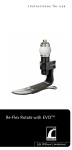
Instructions for use
DVTCare® CA5
Please fill in for future reference
Date purchased:
Serial Number:
General Warnings. . . . . . . . . . . . . . . . . . . . . . . . . . . . . . . . . . . . . . . . . . . . . . . . . . . . . . . . . . . . . . . . 4
Purpose of Device. . . . . . . . . . . . . . . . . . . . . . . . . . . . . . . . . . . . . . . . . . . . . . . . . . . . . . . . . . . . . . . . 4
Intended Uses. . . . . . . . . . . . . . . . . . . . . . . . . . . . . . . . . . . . . . . . . . . . . . . . . . . . . . . . . . . . . . . . . . . 4
Description of Device. . . . . . . . . . . . . . . . . . . . . . . . . . . . . . . . . . . . . . . . . . . . . . . . . . . . . . . . . . . . . 5
Set-Up Instructions. . . . . . . . . . . . . . . . . . . . . . . . . . . . . . . . . . . . . . . . . . . . . . . . . . . . . . . . . . . . . . . 5
Donning the Single / Double Mode Garments.. . . . . . . . . . . . . . . . . . . . . . . . . . . . . . . . . . . . . . . . 6
AC Adapter. . . . . . . . . . . . . . . . . . . . . . . . . . . . . . . . . . . . . . . . . . . . . . . . . . . . . . . . . . . . . . . . . . . . . . 6
Operating Instructions. . . . . . . . . . . . . . . . . . . . . . . . . . . . . . . . . . . . . . . . . . . . . . . . . . . . . . . . . . . . 6
Explanation of button functions.. . . . . . . . . . . . . . . . . . . . . . . . . . . . . . . . . . . . . . . . . . . . . . . . . . . . 7
Explanation of LED indicators. . . . . . . . . . . . . . . . . . . . . . . . . . . . . . . . . . . . . . . . . . . . . . . . . . . . . . 7
Explanation of diagnostic function. . . . . . . . . . . . . . . . . . . . . . . . . . . . . . . . . . . . . . . . . . . . . . . . . . 7
User Maintenance. . . . . . . . . . . . . . . . . . . . . . . . . . . . . . . . . . . . . . . . . . . . . . . . . . . . . . . . . . . . . . . . 8
Environmental Conditions. . . . . . . . . . . . . . . . . . . . . . . . . . . . . . . . . . . . . . . . . . . . . . . . . . . . . . . . . 8
Troubleshooting.. . . . . . . . . . . . . . . . . . . . . . . . . . . . . . . . . . . . . . . . . . . . . . . . . . . . . . . . . . . . . . . . . 9
Contraindications. . . . . . . . . . . . . . . . . . . . . . . . . . . . . . . . . . . . . . . . . . . . . . . . . . . . . . . . . . . . . . . . 9
Storage. . . . . . . . . . . . . . . . . . . . . . . . . . . . . . . . . . . . . . . . . . . . . . . . . . . . . . . . . . . . . . . . . . . . . . . . . 9
Cleaning and Disinfecting.. . . . . . . . . . . . . . . . . . . . . . . . . . . . . . . . . . . . . . . . . . . . . . . . . . . . . . . . 10
Technical Data – DVTCare® Model CA5. . . . . . . . . . . . . . . . . . . . . . . . . . . . . . . . . . . . . . . . . . . . . 10
General Technical Data. . . . . . . . . . . . . . . . . . . . . . . . . . . . . . . . . . . . . . . . . . . . . . . . . . . . . . . . . . . 11
Default Settings. . . . . . . . . . . . . . . . . . . . . . . . . . . . . . . . . . . . . . . . . . . . . . . . . . . . . . . . . . . . . . . . . 12
Tolerances. . . . . . . . . . . . . . . . . . . . . . . . . . . . . . . . . . . . . . . . . . . . . . . . . . . . . . . . . . . . . . . . . . . . . 12
Disposal. . . . . . . . . . . . . . . . . . . . . . . . . . . . . . . . . . . . . . . . . . . . . . . . . . . . . . . . . . . . . . . . . . . . . . . 12
DVTCare® CA5 Electromagnetic Compatibility.. . . . . . . . . . . . . . . . . . . . . . . . . . . . . . . . . . . . . . . 13
General Warnings
warning:Electric shock hazard. Do not remove cover.
warning:Do not attempt to service the pump control unit for any reason. Contact Provider
for instructions (see front cover and/or Provider documentation for contact
information).
warning:If pulsations or throbbing occur, the cuff is wrapped too tight. Loosen
immediately.
warning:Stop using device if swelling occurs; consult physician.
warning:Device to be used only by the patient prescribed, and only for its intended use.
warning:Ensure the pump control unit is turned off and unplugged from the power mains
(wall outlet) prior to and while cleaning or disinfecting.
warning:Equipment not suitable for use in the presence of a flammable anesthetic
mixture with air or with oxygen or nitrous oxide.
warning:Long-time direct contact of the cuffs to the skin may cause some skin irritation,
especially in those with sensitive skin, skin diseases or conditions like allergies or
skin rashes. Consult your doctor if you have any questions regarding your
tolerance for the cuffs or if irritation occurs.
warning:The cuffs are single-use devices. One patient may use a cuff multiple times, but a
single cuff may not be shared between patients.
warning:Not MR-Compatible. Follow Magnetic Resonance Suite safety precautions.
Remove control unit before entering any MR magnetic zone.
caution:Do not immerse in any liquid for any reason.
caution:Do not operate device in a wet environment.
caution:Allow cuffs to warm to room temperature if exposed to temperatures below 5°C.
caution:Do not subject the unit to shocks, such as dropping the pump unit.
caution:Contains no serviceable parts. Contact provider for service (back cover).
caution:Do not place any items in an autoclave.
caution:This unit needs to be installed according to information provided in EMC sec. 38.
caution:Portable and mobile RF communications equipment can affect the operation of
this device.
Purpose of Device
The purpose of the CA5 personal circulation assistant is to aid in the prevention of Deep Vein
Thrombosis (DVT) by helping to stimulate blood flow in the legs. This is accomplished by the
electronically controlled pump unit delivering a set amount of air to the leg cuffs that, in turn,
compress the calf(s) to aid blood flow out of the lower extremities. This pump unit will inflate
to a specified pressure, set by the user or healthcare provider, and deflate once that pressures
is reached. Cycles are repeated until the unit is turned off. Cycle times can only be adjusted by a
healthcare provider. Internal rechargeable batteries allow the system to be completely portable,
thus preventing many interruptions in treatment.
Intended Uses
The DVTCare® CA5 is intended to be a portable system used only by the discretion of a
prescribing medical doctor. Its intended use is primarily to help prevent the onset of DVT in
patients by stimulating blood flow in the legs (simulating muscle contractions). Because of its
portability, a medical doctor may prescribe this device for DVT prophylaxis in persons traveling
or expecting to be stationary for long periods of time (greater than 4 hours). The DVTCare®
CA5 can also, under the control and supervision of physicians and qualifying healthcare
professionals, be used for the treatment of leg ulcers, edema and stasis dermatitis caused by
chronic venous insufficiency in the legs. Additional use, under strict control and monitoring of
a physician, is for the possible enhancement of blood circulation in the legs of patients with
4
arterial ulcers or diabetic ulcers. Furthermore, physicians may choose to use the DVTCare® CA5
for diminishing post-operative pain and swelling and for reducing wound healing time on the
leg or foot.
Description of Device
Set-Up Instructions
note: The DVTCare® CA5 requires EMC precautions, and needs to be installed and put into
service according the EMC information provided on pages 13–15.
note: P
ortable and mobile radio frequency communications can affect the DVTCare® CA5.
1) For future reference, enter the date of purchase and unit Serial Number (found on
the rear label of each pump unit) in the spaces provided on back cover.
2) Remove items from packaging and plastic bags (if present).
3) Make sure all of the pieces listed on page 5 are readily available.
4) Inspect all components for damage. If any parts appear damaged or are
inoperable, contact Provider Customer Service (back cover).
5) Uncoil the tubing attached to the cuff(s).
6) Apply Leg Garments to leg calf (see below). Route tubing under clothing
or in a manner to prevent a tripping hazard and to avoid kinks.
7) Ensure metal thumb tabs on the pump units air outlets are depressed
to allow the air tube connector to engage.
8) Insert pump in pouch and align the outlets with access holes in the pouch
and connect air tube(s) to pump air outlets.
9) Secure carry case as desired using the strap or belt loop provided.
5
Donning the Single / Double Mode Garments
Securing
Tab
Air Tube Fitting
(Inside of Leg)
1) Ensure that the securing tab is on the inside of the garment relative to leg.
2) Place the garment so the tube and elbow fitting are on the inside of the calf,
above the ankle.
3) Wrap the garment around your calf so that it is a snug fit.
4) Adjust as necessary.
warning:If pulsations or throbbing occur, the cuff is wrapped too tightly. Loosen immediately.
warning:If “HI” error occurs ensure that tubing is not kinked and elbow fitting is on interior of
calf above the ankle.
AC Adapter
Insert the supplied power supply plug into the adapter jack in the pump and connect the power
supply adapter to a 100–240V~ wall socket. To maximize performance during extended
operation, connect AC adapter while in use. Full charge is approximately 8.2 volts.
note: Use power supply provided
• Part # MPS-12-001 or DVT67119
• Input: 110–240V~, 50/60Hz, 0.5A
• Output: +12V
1.25 A
note: To isolate unit, unplug from AC adapter/power supply.
Operating Instructions
1) After following the set-up instructions on page 5, ensure leg
cuffs are wrapped firmly around legs as indicated.
2) To turn the system on, press the power button for ½ a second.
3) The system will self diagnose and display either battery
voltage or “AC” (if plugged in), followed by the current pressure setting. If battery voltage
is below 6.9, plug in power supply prior to use. Whenever possible, operate unit with
power supply connected.
4) The Charge status shows “blinking” when unit is being charged and “on” when unit is
fully charged. If the unit will not power on, connect the wall
supply to charge battery. Unit may be used while plugged
into wall outlet.
5) Set pressure by using the and buttons, to either increase
or decrease the set pressure. Pressure adjustments can be
made at any time during the cycle. Press an arrow key for
1mmHg increments and hold the arrow key to scroll in
5mmHg increments.
6
6) Press the “Mode” button to change between single and
double leg modes.
7) While in “Double Leg” mode, only one leg cuff fills at a time.
The leg bladders vent immediately after filling and continue
to vent until the next cycle.
8) Healthcare providers please reference supplemental
instructions for entering the “Healthcare provider access
code” to adjust the upper pressure limit and access the reset function.
9) To maximize performance during extended operation, connect AC adapter while in use.
10) To remove cuff, pull securing straps and unwrap from leg.
11) To disconnect the air tube from pump unit, depress thumb tab on pump unit while
pulling the tube away.
note: I f this system does not inflate or has other malfunctions, consult your Healthcare
Provider immediately for a replacement and for further directions.
Explanation of button functions
• Power
Depress and hold for ½ sec to turn unit on. Depress and hold for 2 sec to turn unit off.
• Up Arrow
Depress briefly to increase pressure by 1mmHg. Depress and hold to increase pressure in
5mmHg increments.
• Down Arrow
Depress briefly to decrease pressure by 1mmHg. Depress and hold to decrease pressure by
5mmHg increments.
• Mode
Depress briefly to change between single-leg and double-leg mode. Confirm garment
connections to “single-leg” fitting when in single-leg mode.
Explanation of LED indicators
The DVTCare® CA5 has 2 operational modes: single leg and dual leg.
• Single-leg mode
Indicates unit is operating in single-leg mode
• Double-leg mode
Indicates unit is operating in double-leg mode.
• Charge status
When power supply is connected to wall supply and unit, and charge light is blinking, unit
is charging. If charge light is on and not blinking, charge is complete. Light is off when not
connected to wall power supply.
Explanation of diagnostic function
• Diagnostic Routine automatically runs at startup and every 30 minutes. You will hear three
short clicks and buzzes as part of the internal diagnostic routine.
7
User Maintenance
warning:
do not attempt to service the pump control unit for any reason.
• Inspect the unit and components for any damage that may have occurred during shipping
or general handling prior to each use (ie: cut cord, split air tubes, cracked plastic housing,
torn cuff, etc). Refer to Description of Device (page 4) for description of all components.
• Do not attempt to connect the wall supply if any damage is noticed.
• Avoid subjecting the unit to shocks, such as dropping the pump unit.
• Notify provider for immediate replacement of any kinked or damaged tubes.
• Do not handle the leg cuffs with any sharp objects. If bladder is punctured, do not repair.
• Roll cuff for storage transportation; avoid folding or creasing the bladder.
• Battery is not replaceable – return unit to provider.
• This device is not protected by a protective earth ground.
Environmental Conditions
• do not expose device to direct sunlight.
• do not operate the pump if it has been stored in freezing conditions. Allow cuffs to warm
to room temperature if exposed to temperatures below 5°C (41°F).
• do not unroll or don the leg cuff in below freezing temperatures (0°C / 32°F) as damage to
the air bladder can occur, making it unable to hold pressure.
• do not expose device to a direct heat source with temperatures exceeding 50°C (122°F) for
extended periods of time.
• Transport temperature and relative humidity: Temperature Range -20°C (-4°F) to +60°C
(140°F); Relative Humidity 30% to 75%; Keep Dry
• Normal Operating Conditions: Temperature Range +10°C (50°F) to +40°C (104°F); Relative
Humidity 30% to 75%. Keep dry.
8
Troubleshooting
Problem
Solution
Air tube outlet connector will not fit in port
Ensure press tab on fittings is depressed.
Unit will not turn on
Battery charge is too low. Connect unit to a wall supply for a fresh
charge and turn on.
Cannot feel pressure on leg(s)
• Fitting on garment is compressed and must be oriented toward
inside of calf above the ankle
• Garment is not wrapped/secured tightly to site
• Air tubes are not connected or kinked
• Bladder is damaged and leaks
• Ensure correct “mode” is selected
Pressure is too high on leg
• Verify settings are as prescribed by physician
• Decrease pressure setting, contact physician
Intermittent
Blink/Beep
Control unit detected
high pressure
Remove kinks and/or restrictions from tubing. Orient Cuff fitting
inside of calf above the ankle. If bladder is full, unplug from unit
momentarily to allow deflation, and reconnect. Allow unit to continue
to cycle.
Steady
Blink/Beep
Control unit detected
high pressure for 10+
Cycles and has ceased
cycling
Remove kinks and/or restrictions from tubing. Orient Cuff fitting
inside of calf above the ankle. If bladder is full, unplug from unit
momentarily to allow deflation, and reconnect. Power unit down and
restart.
Intermittent
Blink/Beep
Control unit detected
low pressure
Inspect fittings at pump, tubing and garment for loose fittings or leaks.
Allow unit to continue to cycle.
Steady
Blink/Beep
Control unit detected
low pressure for 10+
cycles and has ceased
cycling
Inspect fittings at pump, tubing and garment for loose fittings or leaks.
Power unit down and restart.
Battery is low.
Connect to wall supply.
Pump needs to be
reset.
Power off and restart – if condition persists, contact Provider
If problems persist, contact your equipment provider as per back cover.
Contraindications
The DVTCare® CA5 should not be used to treat the following conditions.
• The DVTCare® CA5 system should not be used on patients with suspected, confirmed,
active or untreated Deep Vein Thrombosis or thrombophlebitis.
• The DVTCare® CA5 should not be used on patients with peripheral ischemic vascular
disease or severe peripheral arteriosclerosis, pulmonary edema, congestive heart failure or
active infection, except at the discretion and under strict supervision of a medical doctor.
• The DVTCare® CA5 is not recommended for use on a leg where the cuff would interfere
with the following conditions: vein ligation, gangrene, dermatitis, open wounds, a recent
skin graft, massive edema or extreme deformity of the leg.
• Patients with peripheral neuropathy or who are insensitive to pain or for whom increased
venous or lymphatic return is undesirable should not use this device.
Storage
• Store in a dry location between +10°C (50°F) and +40°C (104°F), 30%–75% relative humidity.
• do not expose to heat exceeding 65°C (149°F).
• do not store items in direct sunlight.
• Ensure zipper/covers of the carry pouch/storage bags are firmly closed to prevent
dust and damage.
9
• Roll cuff and do not fold, as folding will decrease the life of your product.
• Connect unit to charger for recharge no less than 6 hours every 60 days to preserve
integrity of internal batteries.
Cleaning and Disinfecting
note:Inspect the DVTCare® unit and follow the cleaning and disinfecting procedures
prior to each use.
warning:Device must be turned off and disconnected from the wall outlet prior to and
while cleaning or disinfecting.
caution:Contains no serviceable parts. Contact equipment provider for service.
caution:
do not place any items in an autoclave.
caution:
do not immerse pump unit in any liquid for any reason.
• Clean the outer surface of the pump unit using a soft cloth moistened with 70% isopropyl
alcohol or soapy water.
• do not use bleach on any item.
• do not use abrasive or volatile cleaners – display could become scratched and hard to read.
• do not place cuff or carry pouch in dryer, as the bladder could melt.
• Hand wash exterior of cuff and carry pouch using a soft cloth moistened with soapy water
or 70% isopropyl alcohol and let air dry.
• To ensure product is completely dry prior to use, leave unit in the off condition and
disconnected from power (wall outlet) for 30 minutes after cleaning or disinfecting.
Technical Data – DVTCare® Model CA5
Electro Magnetic Compatibility Data on pages 13–15 below.
Refer to user manual for further instructions.
This symbol designates the degree of protection against electrical shock as being a
type BF applied part.
This unit is an electromechanical device that includes printed circuit boards and
rechargeable batteries. Do not discard in landfill. Consult local, state, federal and
country requirements for proper disposal instructions.
Designates Class II medical electrical equipment.
Alternating Current
Direct Current
Fragile
This end up
Temperature Limits
Keep away from rain
10
General Technical Data
note:
The DVTCare® CA5 requires EMC precautions, and needs to be installed and put into
service according the EMC information provided on pages 13–15.
this device is not protected against ingress of water (ordinary protection IPX-0).
Size: 5.9 × 3.9 × 1.6 inches (15 × 10 × 4 centimeters)
Weight: 15 ounces (0.50 kg)
Power:This device is internally powered and operates under continuous
loading. This device is not protected by a protective earth ground.
Equipment not suitable for use in the presence of a flammable
anesthetic mixture with air or with oxygen or nitrous oxide.
Power Supply: MPS-12-001 or DVT67119
Input: 110–240V~, 50/60Hz, 0.5A
Output: +12VDC, 1.25 A
note: This power supply is not approved for hospital,
oxygen rich use.
Battery Run Time *: Single-leg mode: 16 hours*
Double-leg mode: 8 hours*
Recharge time: 3–5 hours
Approximate number of charges: 500 Cycles
* Based on default settings
note: Recharge batteries using only the power supply supplied with
this system. Batteries are best cycled a minimum of once every 60 days
to sustain 500 cycle life.
note: This unit is provided with rechargeable batteries that are not
customer replaceable. Return to provider for service (see back cover).
11
Default Settings
Single-Leg mode
Double-leg mode
Pressure
50 mmHg
50 mmHg
Hold Time
2 secs
2 secs
Cycle Time
60 secs
60 secs
Adjustment Range
Single-Leg mode
Double-leg mode
Pressure
adjustment
20–50 mmHg
20–50 mmHg
Cycle Time
60–75 secs
60–75 secs
The Healthcare Provider can adjust pressure range from 20–65 mmHg if so prescribed.
Tolerances
Pressure
± 4 mmHg
Cycle Time
± 1 second
Displayed battery charge
± 0.1 V
Disposal
This unit is an electromechanical device that includes printed circuit boards and rechargeable
batteries. do not discard in landfill. Consult local, state, federal and country requirements for
proper disposal instructions.
Cuffs may be discarded in US landfill.
12
DVTCare® CA5 Electromagnetic Compatibility
Guidance and manufacturer’s declaration – electromagnetic emissions
(IEC60601-1-2 Table 201)
The DVTCare® CA5 is intended for use in the electromagnetic environment specified below. The customer or the user of
the DVTCare® CA5 should assure that it is used in such an environment.
Emissions Test
Compliance
EMC environment guidance
RF emissions CISPR 11
Group 1
The DVTCare® CA5 uses RF energy for its internal function.
Therefore, its RF emissions are very low and are not likely to
cause any interference in nearby electronic equipment.
RF emissions CISPR 11
Class B
Harmonic emissions IEC 61000-3-2
Class A
Voltage fluctuations/
flicker emissions IEC 61000-3-3
Complies
The DVTCare® CA5 is suitable for use in all establishments,
including domestic establishments and those directly
connected to the public low-voltage power supply network
that that supplies buildings used for domestic purposes.
Guidance and manufacturer’s declaration – electromagnetic emissions
(IEC60601-1-2 Table 202)
The DVTCare® CA5 is intended for use in the electromagnetic environment specified below. The customer or the user of
the DVTCare® CA5 should assure that it is used in such an environment.
EMC environment
guidance
Immunity Test
IEC 60601 test level
Compliance level
Electrostatic discharge
(ESD) IEC 61000-4-2
±6 kV contact
±8 kV air
±6 kV contact
±8 kV air
Floors should be wood,
concrete or ceramic tilt. If
floors are covered with
synthetic material, the
relative humidity should be
at least 30%.
Electrical fast
transient/burst IEC
61000-4-5
±2 kV for power supply lines
±1 kV for input/output lines
±2 kV for power supply
lines
±1 kV for input/output
lines
Mains power quality should
be that of a typical
commercial or hospital
environment.
Surge IEC61000-4-5
±1 kV line(s) to line(s)
±2 kV line(s) to earth
±1 kV line(s) to line(s)
±2 kV line(s) to earth
Mains power quality should
be that of a typical
commercial or hospital
environment.
Voltage dips, short
interruptions and
voltage variations on
power supply input
lines
<5% UT (>95% dip in UT) for
0.5 cycle.
40% UT (60% dip in UT) for 5
cycles.
70% UT (30% dip in UT) for 25
cycles.
<5% UT (>95% dip in UT) for
5 sec
<5% UT (>95% dip in UT)
for 0.5 cycle.
40% UT (60% dip in UT) for
5 cycles.
70% UT (30% dip in UT) for
25 cycles.
<5% UT (>95% dip in UT)
for 5 sec
Mains power quality should
be that of a typical
commercial or hospital
environment. If the user of
the DVTCare® CA5 requires
continued operation during
power mains interruptions, it
is recommended that the
DVTCare® be powered from
an uninterruptible power
supply or battery.
3 A/m
3 A/m
Power frequency magnetic
fields should be at levels
characteristic of a typical
location in a typical
commercial or hospital
environment.
IEC 61000-4-11
Power frequency
(50/60 Hz) magnetic
field IEC 61000-4-8
note: UT is the a.c. mains voltage prior to application of the test level.
13
Guidance and manufacturer’s declaration – electromagnetic emissions for
non-life support equipment (IEC60601-1-2 Table 204)
The DVTCare® CA5 is intended for use in the electromagnetic environment specified below. The customer or the user
of the DVTCare® CA5 should assure that it is used in such an environment.
Immunity Test
IEC 60601 test
level
Compliance
level
EMC environment guidance
Portable and mobile RF communications equipment
should be used no closer to any part of the DVTCare®
CA5, including cables, than the recommended
separation distance calculated from the equation
applicable to the frequency of the transmitter.
Recommended separation distance:
Conducted RF IEC
61000-4-6
3 Vrms
150 KHz to 80 KHz
3 Vrms
Radiated RF IEC
61000-4-3
3 V/m 80 MHz to
2.5 GHz
10 V/m
d = 1.2 √P
d = .35 √P 80MHz to 800 MHz
d = .70 √P 800MHz to 2.5 GHz
where P is the maximum output power rating of the
transmitter in watts (W) according to the transmitter
manufacturer and d is the recommended separation
distance in meters (m).
Field strengths from fixed RF transmitters, as
determined by an electromagnetic site survey* should
be less than the compliance level in each frequency
range**.
Interference may occur in the vicinity of equipment
marked with the following symbol:
note 1: At 80 MHz and 800 MHz, the higher frequency range applies.
note 2: These guidelines may not apply in all situations. Electromagnetic propagation is affected by absorption and
reflection from structures, objects and people.
  * Field strengths from fixed transmitters, such as base stations for radio (cellular/cordless) telephones and land
mobile radios, amateur radio, Am and FM radio broadcast and TV broadcast cannot be predicted theoretically with
accuracy. To assess the electromagnetic environment due to fixed RF transmitters, an electromagnetic site survey
should be considered. If the measure field strength in the location in which the DVTCare® CA5 is used exceeds the
applicable RF compliance level above the DVTCare® CA5 should be observed to verify normal operation. If
abnormal performance is observed, additional measures may be necessary, such as reorienting or relocation the
DVTCare® CA5.
** Over the frequency range 150 kHz to 80 MHz, field strengths should be less than 3 V/m.
14
Recommended separation distances between portable and mobile RF communications
equipment and the DVTCare® CA5 (IEC60601-1-2 Table 206)
The DVTCare® CA5 is intended for use in the electromagnetic environment in an electromagnetic environment in which
radiated RF disturbances are controlled. The customer or the user of the DVTCare® CA5 can help prevent
electromagnetic interference by maintaining a minimum distance between portable and mobile RF communications
equipment (transmitters) and the DVTCare® CA5 as recommended below, according to the maximum output power of
the communications equipment.
Rated maximum
output power of
transmitter (W)
Separation distance according to frequency of transmitter (m)
150 kHz to 80 MHz
d = 1.2√P
80 MHz to 800 MHz
d = .35√P
800 MHz to 2.5 GHz
d = .70√P
0.01
0.12
0.04
0.07
0.10
0.38
0.11
0.22
1.00
1.20
0.35
0.70
10.00
3.80
1.10
2.20
100.00
12.00
3.50
7.00
For transmitters rated at a maximum output power not listed above, the recommended separation distance of “d” in
meters (m) can be estimated using the equation applicable to the frequency of the transmitter, where “P” is the
maximum output power rating of the transmitter in watts (W) according to the transmitter manufacturer.
note 1: At 80 MHz and 800 MHz, the separation distance for the higher frequency range applies.
note 2: These guidelines may not apply in all situations. Electromagnetic propagation is affected by absorption and
reflection from structures, objects and people.
note:The use of accessories, transducers and cables other than those specified, with
the exception of transducers and cables sold by the manufacturer of the
DVTCare® CA5 as replacement parts for internal components, may result in
increased emissions or decreased immunity of the DVTCare® CA5.
note:The DVTCare® CA5 should not be used adjacent to or stacked with other
equipment. If adjacent or stacked use is necessary, the DVTCare® CA5 should be
observed to verify normal operation in the configuration in which it will be used.
15
Össur Americas
27051 Towne Centre Drive
Foothill Ranch, CA 92610, USA
Tel: +1 (949) 382 3883
Tel: +1 800 233 6263
Fax: +1 800 831 3160
[email protected]
Össur Canada
2150 – 6900 Graybar Road
Richmond, BC
V6W OA5 , Canada
Tel: +1 604 241 8152
Fax: +1 866 441 3880
Össur Europe
Ekkersrijt 4106-4114
P.O. Box 120
5690 AC Son en Breugel
The Netherlands
Tel: +800 3539 3668
Tel: +31 499 462840
Fax: +31 499 462841
[email protected]
Össur Deutschland GmbH
Augustinusstrasse 11A
50226 Frechen
Deutschland
Tel: +49 (0) 2234 6039 102
Fax. +49 (0) 2234 6039 101
[email protected]
Össur Nordic
P.O. Box 67
751 03 Uppsala, Sweden
Tel: +46 1818 2200
Fax: +46 1818 2218
[email protected]
Össur Europe BV – Italy
Via Baroaldi, 29
40054 Budrio, Italy
Tel: +39 05169 20852
Fax: +39 05169 22977
[email protected]
Össur Iberia S.A.
Calle Caléndula, 93 Miniparc III
Edificio E, Despacho M18
28109 El Soto de la Moraleja,
Alcobendas
Madrid – España
Tel: 00 800 3539 3668
Fax: 00 800 3539 3299
[email protected]
Össur Asia
2F, W16 B
No. 1801 Hongmei Road
200233, Shanghai, China
Tel: +86 21 6127 1700
Fax: +86 21 6127 1799
[email protected]
Össur UK
Unit No 1
S:Park
Hamilton Road
Stockport SK1 2AE, UK
Tel: +44 (0) 8450 065 065
Fax: +44 (0)161 475 6321
[email protected]
Össur Asia-Pacific
26 Ross Street,
North Parramatta
Sydney NSW, 2152 Australia
Tel: +61 2 88382800
Fax: +61 2 96305310
[email protected]
Össur Head Office
Grjótháls 5
110 Reykjavík, Iceland
Tel: +354 515 1300
Fax: +354 515 1366
[email protected]
www.ossur.com
©Copyright Össur 2013
IFU 0576 Rev. 2