1
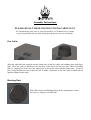
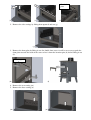
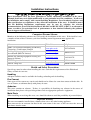
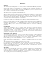
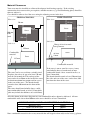
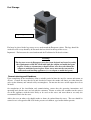
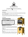
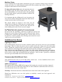
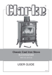
N Ø R R E S K O V E N
M U L T I F U E L
S T O V E
Installation and Operating Instructions
An accredited competent person must carry out the installation of this appliance;
alternatively, your local Building Control Officer can approve the completed
installation, should a non-accredited engineer undertake the installation. It is an
offence, under UK law, not to comply with this advice. Please hand these
instructions to the stove user when the installation is complete. Leave the system
ready for operation and instruct the user in the correct use of the appliance and
operation of controls.
v03.10
Nørreskoven
Technical Specification
Stove Mass
100 kg
DS/EN 13240
Total Efficiency
Nominal Heat Output
Mean CO Emission (at 13% O2)
Mean OGC Emission (at 13% O2)
Mean Flue Gas Temperature
Flue Gas Mass Flow
82.0 %
4.9 kW
0.10 %
96 mg/nm3
220 °C
4.7 g/s
(Figures based on a fuel load of 1.4 kg wood logs with primary air closed and secondary air 50% open)
NS 3058/59
Average particulate emission
Maximum particulate emission
3.27 g/kg
3.49 g/kg
This appliance is not suitable for use in a shared flue
This appliance is suitable for intermittent burning
Assembly Instructions
PLEASE READ THESE INSTRUCTIONS CAREFULLY
It is important that your stove is correctly installed, as Cleanburn Stoves cannot
accept responsibility for any fault arising through incorrect use or installation.
Flue Collar
Wind the eight M6 studs supplied into the fixing holes in the flue collar and blanking plate until finger
tight. Place the gasket in position on the top plate of the stove and lower the flue collar or blanking
plate (as required) on to the stove top, taking care to line up the studs with the fixing holes. Secure in
place using the M6 nuts and washers. Fit the two M8 coach bolts in the flue collar to blank off the
optional damper handle holes.
Blanking Plate
Fit the Flue Gasket and Blanking Plate on the remaining free outlet
and secure it, using the two M6 studs.
Removing Internal Parts
This set of instructions explains the removal sequence that you will need to employ when servicing
your Cleanburn stove.
1. Open the stove door(s) and remove the ash pan.
2. Remove the baffle by pulling it forwards and sliding it to the left until the right side of it clears
the baffle support and then lowering it into the firebox and removing it (a).
3. Remove the grate bars by lifting them out in pairs (b).
(b)
(a)
4. Remove the side bricks by lifting them up and swinging the bottom end towards the centre of
the stove (c).
5. Remove the rear brick (d).
(c)
(d)
1. Remove the cam bar by lifting the left-hand end of it upwards until it clears the side casting,
pulling the left-hand end towards the front of the stove until it is outside the stove (d) and then
sliding it all the way out (e), taking care not to lose the cam hole plate.
Cam hole
plate
(d)
(e)
(f)
2. Remove the side castings by lifting them upwards and out (g).
(g)
3. Remove the front plate by lifting it out. On double-door stoves it will be necessary to push the
front plate towards the back of the stove to free it from the location pins (h) before lifting it out
(k).
Location pin
(k)
(h)
4. Remove the rear casting (m).
5. Remove the base casting (n).
(m)
(n)
Installation Instructions
These instructions cover the basic principles to ensure satisfactory installation of the stove,
although detail may need slight modification to suit particular local site conditions. In all cases
the installation must comply with current Building Regulations, Local Authority Byelaws and
other specifications or regulations as they affect the installation of the stove. It should be noted
that the Building Regulations requirements may be met by adopting the relevant
recommendations given in British Standards BS 8303 and BS EN 15827-1:2007 as an alternative
means to achieve an equivalent level of performance to that obtained following the guidance
given in Approved Document J.
Competent Persons Scheme
Members of the following schemes may self-certify the installation of this stove. If the installer is not
a member of one of these schemes, your local building control department must approve the
installation.
Scheme
APHC (Association of Plumbing and Heating
Contractors (Certification) Limited
Building Engineering Services Competence
Accreditation (BESCA Limited)
HETAS Ltd (Heating Equipment Testing and
Approval Scheme)
NAPIT Registration Ltd
NICEIC Group Ltd
Web address
Telephone
www.aphc.co.uk
02476 470 626
www.hvca.org.uk /
www.besca.org.uk
0800 652 5533
www.hetas.co.uk
01462 634721
www.napit.org.uk
www.niceic.org.uk
0870 444 1392
0800 013 0900
Health and Safety Precautions
Special care must be taken when installing the stove such that the requirements of the Health and
Safety at Work Act are met.
Handling
Adequate facilities must be available for loading, unloading and site handling.
Fire Cement
Some types of fire cement are caustic and should not be allowed to come into contact with the skin. In
case of contact, wash immediately with plenty of water.
Asbestos
This stove contains no asbestos. If there is a possibility of disturbing any asbestos in the course of
installation then please seek specialist guidance and use appropriate protective equipment.
Metal Parts
When installing or servicing this stove, care should be taken to avoid the possibility of personal injury.
Important Warning
This stove must not be installed into a chimney that serves any other heating appliance.
There must not be an extractor fan fitted in the same room as the stove as this can cause the stove to
emit fumes into the room.
Installation
Chimney
The chimney height and the position of the chimney terminal should conform to Building Regulations.
Check that the chimney is in good condition, dry, free from cracks and obstructions. The diameter of
the flue should not be less than 150mm and not more than 230mm. If any of these requirements are not
met, the chimney should be lined by a suitable method.
The chimney must be swept before connection to the stove.
Where the chimney is believed to have previously served an open fire installation, it is possible that the
higher flue gas temperature from the stove may loosen deposits that were previously firmly adhered,
with the consequent risk of flue blockage. It is therefore recommended that the chimney be swept a
second time within a month of regular use after installation.
If you have any doubts about the suitability of your chimney, consult your local dealer/stockist.
If there is no existing chimney then either a prefabricated block chimney in accordance with Building
Regulations Approved Document J, or a twin-walled insulated stainless steel flue to BS 4543 can be
used. These chimneys must be fitted in accordance with the manufacturer’s instructions and Building
Regulations.
Flue Draught
A flue draught of minimum 1.2mm to a maximum 2.5mm water gauge is required for satisfactory
appliance performance. The flue draught should be checked under fire at high output. If it exceeds the
recommended maximum, a draught stabiliser must be fitted so that the rate of burning can be
controlled and to prevent over firing. If the reading is less than the recommended minimum then the
performance of the appliance will be compromised.
Connection to the Chimney
An existing fireplace opening can be bricked up or sealed with a register plate. A short length of flue
pipe of a minimum 127mm internal diameter may then be used to connect the stove to the chimney.
This flue pipe should be of 316 grade stainless steel or vitreous enamelled, nominal thickness 1.2mm.
Ensure that the pipe end is no closer than 76mm to the side or rear chimney walls.
Ideally, the old fireplace should be filled in so that there is a smooth streamlined entry into the flue
way.
The length of any horizontal run of flue pipe must not exceed 127mm.
It is essential that all connections between the stove and chimney-flue are sealed and made airtight.
Both the chimney and flue pipe must be accessible for cleaning and if ANY parts of the chimney
cannot be reached through the stove (with baffle brick removed), a soot door must be fitted in a
suitable position to enable this to be done.
Air Supply
The room or space containing this appliance needs no additional ventilation, unless a draught stabiliser
is fitted, in which case a permanent air opening of at least 1470mm2 should be provided. Due
consideration should be given to air requirements for any other appliances in the same room or space.
Any air opening must be kept clear from blockage or obstruction.
Material Clearances
Your stove must be installed on a floor with adequate load-bearing capacity. If the existing
construction does not meet this pre-requisite, suitable measures (e.g. load distributing plate) should be
taken to achieve it.
Care should be taken to level the stove using the adjusting screws in the feet.
FREE-STANDING
FIREPLACE RECESS
Plan view:
Plan view:
150 mm
50 mm
150 mm
Stove
Stove
500 mm
from
jamb
150 mm
300 mm
300 mm
Side view:
Side view:
Change in level to mark
safe perimeter
150 mm
Combustible
material
At least
12mm
Stove
Stove
125 mm
Combustible material
The stove can be recessed into a suitably sized
fireplace, but a free air gap of at least 150 mm
must be left around the sides and top of the
stove and at least 50mm at the back of the stove
to obtain maximum heat output and for access
to the rear of the stove. The hearth should
extend at least 300 mm from the front of the
stove.
The stove should stand wholly above a solid,
non-combustible hearth, at least 125 mm thick
(this may include the thickness of a solid floor).
If the stove is not to stand in a recess, it may
stand wholly above a hearth made of noncombustible board / sheet material or tiles, at
least 12mm thick.
The hearth should extend at least 150 mm from
the sides and rear of the stove, and at least 300
mm from the front of the stove.
All walls shown in the above diagrams are non-combustible unless otherwise indicated. All noncombustible walls closer than 300mm to the stove should be at least 75mm thick.
MINIMUM DISTANCE TO COMBUSTIBLE MATERIAL
Behind the stove
At the side of the stove
To furniture (in front of the stove)
550mm
200mm
700mm
Note: combustible material refers to any material that will degrade when subjected to heat e.g. plaster.
Fuel Storage
log storage recess
Fuel may be placed in the log storage recess underneath the European variant. The logs should be
stacked in such a way that they do not touch the heat shield at the top of the recess.
Important! - Fuel must not be stored underneath the Traditional or Pedestal variants.
Warning!
The log store recess in European stoves has been designed and tested to satisfy
the requirements of BS EN 13240 with both the ashpan and multi-fuel grate
in place. Under no circumstances should a Euro stove be used without the
ashpan or multi-fuel grate in place. Euro stoves must not be converted to
dedicated wood burning appliances (i.e. no ashpan or multi-fuel grate).
Commissioning and Handover
Upon completion of the installation, allow a suitable period of time for any fire cement and mortar to
dry out. A small fire may then be lit and checked to ensure the smoke and fumes are taken from the
stove up the chimney and emitted safely to atmosphere. Do not run the stove at full output for at least
24 hours.
On completion of the installation and commissioning, ensure that the operating instructions and
operating tools for the stove are left with the customer. Ensure to advise the customer on the correct
use of the appliance with the fuels likely to be used on the stove and warn them to use only the
recommended fuels for the stove.
Advise the user on what to do should smoke or fumes be emitted from the stove. The user should be
warned to use a fireguard to BS 6539 in the presence of children, aged and/or infirm persons.
Operating Instructions
This appliance is not suitable for use in a shared flue
This appliance should not be operated with the doors open
Aerosol Sprays
Do not use an aerosol spray on or near the stove when it is alight.
Air Controls
This stove has been designed to burn cleaner and more efficiently than a conventional wood burning
stove. If used correctly this stove will burn far more efficiently than normal with the obvious notable
feature of CLEAN GLASS.
However, for this product to work properly it must be used correctly.
It is essential that the stove has an adequate air supply for combustion and ventilation.
The primary, secondary and tertiary air inlets must be kept clear from obstruction and blockage.
Air Controls
Secondary Air Control (Open Right)
Warning!
This Appliance will be hot when in operation and
due care should be taken. The riddling tool may
be used to operate the door handle. The supplied
gloves could be used to operate the primary and
secondary air controls.
Primary Air Control (Open Right)
Primary Air
The Slider under the ash-lip of the stove controls the Primary air.
This provides a conventional air draught to the bed of the fire.
The control is open when the Slider is pushed towards the right of
the Stove.
Secondary Air
Secondary air is controlled via the slider above the doors; it is
this “Airwash” that keeps a clean and uninterrupted view of the
fire.
Tertiary Air
Tertiary air aids in good secondary combustion of the fuel and
reducing emissions into the chimney and environment. Adjusting
the cover plate on the back of the Stove can control tertiary air.
Multifuel Grate
Your Cleanburn Stove is fitted with a locomotive type grate. So that de-ashing can be carried out
cleanly and easily, it is riddled from the outside of the stove with the doors closed. The grate is
designed to burn both wood and solid fuels.
To burn solid mineral fuels place the operating tool over
the riddling spigot and pull it down towards you. When
left in that position, air is directed under and up through
the slots in the firebed, giving the optimum conditions for
burning solid fuels.
It is important that the riddling tool is used to remove the
ash to ensure airflow through the firebed and allow the fire
to burn over the entire area of the grate.
The ashpan should be emptied at least daily and ash
should never be allowed to build up over a period of time
as this will result in damage to the fire bars. The flat end
of the riddling tool can be used to carry the ashpan.
To burn wood, push the operating tool up and away from
you. When left in this position, air is restricted through
the bed of the fire providing a solid base to build up a bed of ash.
Surplus ash can be removed either by gentle riddling or with a shovel.
It might prove beneficial when burning more reactive fuels to leave
the grate in a “neutral” position, thus directing some under fire air and
some over fire air to the firebed.
Solid Mineral Fuel Burning
Lighting the Stove
We recommend that you have two or three small fires before you operate your stove to its maximum
heat output. This is to allow the paint to cure in steadily and to give a long service life of the paint
finish. During this curing in process you may notice an unpleasant smell. It is non-toxic, but for
your comfort we would suggest that during this period you leave all doors and windows open.
First, load the fire with starting fuel, i.e. paper, dry sticks and/or firelighters in the mode chosen,
either wood or solid mineral fuel. Light the fire at the base leaving all air controls open. Allow the
fuel to reach a steady glow and build the fire up gradually. Once you have a good fire established
across the grate bed, further fuel can be added as required.
Recommended Solid Mineral Fuels
Only authorised fuels may be used in UK smoke control areas. A list of authorised fuels can be
found at http://uksmokecontrolareas.co.uk/fuels.php
HETAS Ltd Approval
This appliance has obtained HETAS Ltd approval for burning dry seasoned wood logs. Approval
does not cover the use of other fuels either alone or mixed with the recommended fuel, nor does it
cover instructions for the use of other fuels.
Warning!- Petroleum coke fuels or household waste must not be burnt on this appliance.
Should any difficulties arise over fuel quality or suitability, consult your local approved coal
merchant or:
HETAS Ltd.– Telephone 01242 673257 – www.hetas.co.uk
Solid Fuel Association – Telephone 0800 600 000 – www.solidfuel.co.uk
Loading the Stove (Solid Mineral Fuel)
Solid mineral fuel should be placed in the stove so that there is no more than a 30° incline of the
fuel bed from front to back. It should not be stacked above the level of the rear firebrick as this
may result in damage to the stove.
With a full load of fuel, the stove will need to be refuelled approximately once every 4 hours.
Air Controls (Solid Mineral Fuel)
Solid mineral fuel burns most efficiently with the secondary air control in the closed position. The
primary air lever can then be used to control the burn rate of the stove.
Always de-ash before refuelling and do not let the ash level reach the underside of the grate bars.
Solid mineral fuel produces ash, which if allowed to build-up will stifle the airflow through the
Primary air inlets and grate. This will eventually cause the fire to die.
With some solid mineral fuels a residue of burnt fuel or clinker will accumulate on the grate, allow
the fire to go out periodically to remove this.
Important! - We cannot stress firmly enough how important it is to empty the ashpan regularly. Air
passing through the firebed cools the grate bars. Distortion or burning out the grate bars is nearly
always caused by ash being allowed to build up to the underside of the grate.
Extended Burning (Solid Mineral Fuel)
The stove can be banked up for extended burning. When burning solid fuel, empty the ashpan.
Open air controls and let the fire burn brightly for a short period. Refuel and close both air controls,
the exact setting required will depend on the fuel used and the chimney draw so some practice may
be necessary. To revive the fire, open the air controls until the fire is burning brightly de-ash if
necessary and refuel. Set air controls as required.
Wood burning
Lighting the Stove
We recommend that you have two or three small fires before you operate your stove to its maximum
heat output. This is to allow the paint to cure in steadily and to give a long service life of the paint
finish. During this curing in process you may notice an unpleasant smell. It is non-toxic, but for
your comfort we would suggest that during this period you leave all doors and windows open.
First, load the fire with starting fuel, i.e. paper, dry sticks and/or firelighters in the mode chosen,
either wood or solid mineral fuel. Light the fire at the base leaving all air controls open. Allow the
fuel to reach a steady glow and build the fire up gradually. Once you have a good fire established
across the grate bed, further fuel can be added as required.
Loading the Stove (Wood)
With a full load of wood, the stove will need to be refuelled approximately once every hour.
Wood can be stacked higher in the stove than solid mineral fuel but care must be taken that logs do
not touch the brick baffle.
Air Controls (Wood)
Wood burns most efficiently with the primary control in the closed position and the secondary
control approximately 60% open. Moving the secondary control will control the burn rate of the
stove.
The secondary air lever should not be completely closed unless the primary air lever is also in the
closed position.
Wood burns best on a bed of ash and it is therefore only necessary to remove surplus ash from on
top of the grate occasionally. Do not let the ash level under the grate reach above the primary air
inlet holes. If allowed to build-up, ash will stifle the airflow through the grate.
Burn only dry, well-seasoned wood, which should have been cut, split and stacked for at least 12
months, with free air movement around the sides of the stack to enable it to dry out. Burning wet or
unseasoned wood will create tar deposits in the stove and chimney and will not produce a
satisfactory heat output.
Extinguishing the Fire
In order to reduce the rate of combustion, close the primary air lever and then the secondary air
lever by moving the handles all the way to the left. If the controls are left in this position, the fire
will be starved of air and go out. If you want to revive the fire it is recommended that the primary
air control is open first, then open the secondary air slider.
Warning!- The stove will remain hot for a considerable time after the fire has been extinguished.
Safety notes for your guidance
FIRES CAN BE DANGEROUS – Always use a fireguard in the presence of children, the elderly
or the infirm. The fireguard should be manufactured in accordance with BS 6539 – Fireguards for
use with solid fuel appliances.
DO NOT OVERFIRE – it is possible to fire the stove beyond its design capacity, this could
damage the stove, so watch for signs of overfiring – if any part of the stove starts to glow red, the
fire is in an overfire situation and the controls should be adjusted accordingly. Never leave the
stove unattended for long periods without first adjusting the controls to a safe setting – careful air
supply control should be exercised at all times.
WARNING – FUME EMISSION
Properly installed and operated, this appliance will not emit fumes. Occasional fumes from deashing and refuelling may occur. Persistent fume emission must not be tolerated.
If fume emission does persist, then the following immediate action should be taken: 1.
2.
3.
4.
Open doors and windows to ventilate room.
Let the fire out, or eject and safely dispose of fuel from the appliance.
Check for flue chimney blockage and clean if required.
Do not attempt to re-light the fire until the cause has been identified and corrected.
If necessary, seek professional advice.
Adverse weather – In a small number of installations, occasional local weather conditions (e.g.
wind from a particular direction) may cause downdraught in the flue and cause the stove to emit
fumes. In these circumstances, the stove should not be used. A professional flue installer will be
able to advise on solutions to this problem (e.g. anti-downdraught cowl).
Important! – Do not fit an extractor fan in the same room as this appliance.
IN THE EVENT OF A CHIMNEY FIRE
•
•
•
•
•
•
Raise the alarm to let others in the house know.
Call the Fire Brigade.
Reduce the appliance-burning rate by closing all air controls.
Move furniture and rugs away from the fireplace and remove any nearby ornaments.
Place a fireguard or spark guard in front of the stove.
Feel the chimneybreast for signs of excessive heat.
If the wall is becoming hot, move the furniture away. Ensure that the Fire Brigade can gain access
to your roof space in order to check this area for signs of fire spread.
GENERAL MAINTENANCE
NO unauthorised modification of this appliance should be carried out.
IMPORTANT! - In order to ensure continued compliance with current Building Regulations,
Local Authority Byelaws and the Clean Air Act (if applicable), this appliance requires regular
maintenance of the following:
Monthly
Baffle, Grate Bars and Fire Box Components
These should be removed and cleaned at least once a month to prevent any build up of soot or
ash that could lead to blocked flue ways, blocked air inlets and dangerous fume emission.
If the baffle is removed the chimney/flue way can be swept through the appliance.
Glass Panels
Clean the glass panels when cool with a proprietary glass cleaner. Highly abrasive substances
should be avoided as these can scratch the glass and make subsequent cleaning more difficult.
Wet logs on heated glass, a badly aimed poker or heavy slamming of the doors could crack the
glass panels. The glass will not fracture from heat.
Firebricks
In normal use, these can last for many years. It is possible however, to crack them if logs are
continually jammed against them or if they are frequently struck with a poker.
Check periodically for seriously cracked bricks, which can be replaced with new; available from
your dealer.
Rope
Check the rope around the door and glass. If rope is becoming detached, use proprietary rope
glue to re-attach it. If the rope is in a poor condition, a replacement rope kit may be ordered
from the Cleanburn Stoves spares range.
Annually
Annual maintenance of the following should be carried out by a competent person:
Chimney and Flueways
It is important that the chimney, flue ways and any connecting flue pipe are swept regularly.
This means at least once a year for smokeless fuels and at least twice a year for wood and other
fuels. The baffle will need to be removed from its supports in order to sweep the chimney (see
assembly instructions).
Only wire-centred sweeps’ brushes fitted with a guide wheel should be used.
If it is not possible to sweep all parts of the chimney through the appliance, ensure there is
adequate access to cleaning doors.
If the stove is fitted in place of an open fire, then the chimney should be swept one month after
installation to clear any soot falls which may have occurred due to the difference in combustion
between the stove and the open fire.
Periods of Prolonged Non-Use - If the stove is to be left unused for a prolonged period of time
then it should be given a thorough clean to remove ash and unburned fuel residues. To enable a
good flow of air through the appliance to reduce condensation and subsequent damage, leave the
air controls fully open
If the appliance has been unused for a long period of time, such as during the spring and summer
months, a competent person should check the chimney for potential obstructions before lighting
the stove.
As Necessary
Gaskets
All gasket used on this appliance are produced from a heat resistant material called Manniglas.
The glass gasket will have to be replaced when a new piece of glass is fitted as the gaskets
become brittle after firing the stove. Over time, you may also find, that the gasket changes
colour. This is due to a reduction in the pigment used in the manufacture of the product and no
cause for concern.
Stove Body
The stove is finished with a heat resistant paint and this can be cleaned with a soft brush. Do not
clean whilst the stove is hot; wait until it has cooled down. The finish can be renovated with
proprietary stove paint.
Single Door Catch
The door catch may require adjustment to maintain the door seal. By slackening the locking nut
and turning the door handle one turn you will achieve a tighter lock when the door is closed.
Double Door Catch
The door catch may require adjustment to maintain the door seal. By slackening the socket set
screw and turning the catch shaft one turn you will achieve a tighter lock when the door is closed.
Troubleshooting
Fire will not burn
Check that:
1. The air inlet is not obstructed in any way.
2. Chimneys and flue ways are clear.
3. A suitable fuel is being used.
4. There is an adequate air supply into the room.
5. An extractor fan is not fitted in the same room as the stove.
6. Flue draught is above minimum level (see installation instructions).
Fire blazing out of control
Check that:
1. The doors are tightly closed.
2. The air controls are all in the closed position.
3. The Primary air control flap is not wedged in the open position.
4. A suitable fuel is being used.
5. The glass retaining clips are not loose.
6. The door rope seals are in good condition
7. Flue draught is below maximum level (see installation instructions).
STOVE SPARES
SINGLE DOOR
Door Handle Assembly
Door Handle
HCE05/035
Handle Spacer
HCE05/036
Handle Nut
HCE05/037
Shaft, Door Handle
HCE05/038
Circlip
FLRX07
M8 Full Nut
FSHM08
Door Catch
HMS04/037
Single Door
HMS04/002
Door Glass
HMS04/053
Glass Gasket
HMS04/055
Glass Clip & Screw
HHR08/046
FSJM05008SS
DOUBLE DOORS
L.H. Door
HMS04/006
R.H. Door
HMS04/004
Door Glass
HMS04/054
Glass Gasket
HMS04/056
Glass Clip & Screw
HHR08/046
FSJM05008SS
PRIMARY AIR VALVE
Slider Knob
HCE05/040
Front Shaft
HCE05/033
Gasket
HMS04/046
Control Boss
HCE05/034
Cast Iron Valve
HMS04/044
Support
HCE05/031
Rear Shaft
HCE05/032
BODY ASSEMBLY - PART SECTION - MULTIFUEL
Top Air Parts
Slider
HCR06/072
Slider Shaft
HCE05/021
Slider Knob
HHR08/045
Slider Plate
HCR06/076
Deflector
HCR06/077
Flue Gaskets
CH05/042
Flue Collar
CH05/010
Flue Cover
CH05/011
Baffle Back
HCE06/021
Baffle Bricks
HCE06/022 – 1
HHW08/038 – 2
Turbo Bar
HCE05/048M
Side Bricks
HCE05/010
Rear Brick
HCE05/009
Front Plate
Single-Door, HCE05/061
Double-Door, HCE05/075
Riddling Support
HCE05/043
Fixing Stud
FDSM08040
M8 Lock Nut
FNLM08
Thumb Nut
FNTM08WDS
Cast Iron Side Plates
L.H. HCE05/044
R.H. HCE05/045
Cam Bar
HCE06/010
Ashpan
HCE05/011
Cast Iron Inner Base
HCE05/042M
Cam Hole Plate
HCE06/030
Riddling Bars
Lower, CNS04/012 (6)
Upper, CNS04/013 (5)
QUARTER TURN DOOR HANDLE - DOUBLE DOOR - MULTIFUEL - PARTS
Catch End
HCE09/089
Catch Shaft
HCE05/082
M12 Half Nut
FNLM12Z
Catch Boss
HCE09/090S
3mm x 10mm Roll Pins
FPGM03010
Catch Collar
HCE09/092S
Snap Ring
FLRWM0160
4mm x 14mm Roll Pin
FPGM04014
Catch Spacer
HCE05/081S
Catch Barrel
HCE09/091
Door Handle
HCE05/035
M3 Ball Bearing
FBBM03C
M6 Socket Set Screw
FSGM06006CP