1
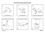
Ergo Kiosk User Guide Before operating the unit, please read this manual thoroughly, and retain it for future reference User manual Notice 1. When disconnecting the display from an electrical outlet, the plug must be pulled out from the socket. Do not remove power cord from outlet by pulling from the cord. Pull from the plug head. 2. WARNING – To reduce the risk of fire or electric shock, do not expose this appliance to rain or other forms of moisture. 3. Display must not be exposed to liquids via dripping or splashing. Please do not place liquid –filled items such as vases near the display. 4. Use only a properly grounded plug and receptacle. 5. CAUTION – These instructions are for use by qualified service personnel only. To reduce the risk of electric shock, do not perform any service other than that contained in the operating instructions unless you are qualified to do so. CAUTION RISK OF ELECTRIC SHOCK DO NOT OPEN CAUTION : TO REDUCE THE RISK OF ELECTRIC SHOCK, DO NOT REMOVE COVER (OR BACK). NO USER-SERVICEABLE PARTS INSIDE. REFER SERVICING TO QUALIFIED SERVICE PERSONNEL. This symbol is intended to alert the user to the presence of insulated “dangerous voltage” within the product’s enclosure that may be of sufficient magnitude to constitute a risk of electric shock to persons. This symbol is intended to alert the user to the presence of important operating and maintenance (servicing) instructions in the literature accompanying the product. www.gpodisplay.com 2 Ergo Kiosk User manual Important Safety Instructions 1. 2. 3. 4. 5. 6. 7. 8. Read these instructions. Keep these instructions. Heed all warnings. Follow all instructions. Do not use this product near water. Clean only with dry microfiber cloth. Do not block any ventilation openings. Install in accordance with the manufacturer’s instructions. Do not install near any heat sources such as radiators, heat registers, stoves, or other display (including amplifiers) that produce heat. 9. Do not remove ground prong from three-pronged plugs. If your outlet will not accept threepronged plugs, consult an electrician for replacement. 10. Protect the power cord from being walked on or pinched, particularly at plugs, convenience receptacles, and the point where they exit from the display. 11. Only use attachments/accessories specified by the manufacturer. 12. Use only with the cart, stand, tripod, bracket, or table specified by the manufacturer, or sold with the display. When a cart is used, exercise caution when moving the cart/display combination to avoid injury from tip-over. 13. Unplug this display during lightning storms or when unused for long periods of time. 14. Refer all servicing to qualified service personnel. Servicing is required when the display has been damaged in any way, such as power-supply cord or plug is damaged, liquid has been spilled or objects have fallen into the display, the display has been exposed to rain or moisture, does not operate normally, or has been dropped. 15. Do not expose this display to dripping or splashing and ensure that no objects filled with liquids, such as vases, are placed on the display. 16. To completely disconnect this display from the wall outlet, disconnect the power supply cord plug from the AC receptacle./wall socket 17. The mains plug of the power supply cord shall remain readily operable. 18. An display with CLASS I construction shall be connected to a wall socket outlet with a protective grounding connection. 19. Note: Prolonged use of headphones at a high volume may cause damage your ears. 20. Notice to users : This is a Class A digital device 21. This device is designed for commercial use and features safety certificates for electromagnetic interference (EMI). Users should be mindful of EMI issues. www.gpodisplay.com 3 Ergo Kiosk User manual Accessories CD Remote Control HDMI Cable Power Cable Batteries (AAA x 2) 1. SOURCE : Selects Input Source 2. POWER : Turns the LCD Display On and Off 3. UP : Controls the UP cursor in the menu 4, LEFT : Controls the LEFT cursor in the menu 5. RIGHT : Controls the RIGHT cursor in the menu 6. DOWN : Controls the DOWN cursor in the menu 7. ENTER : Controls the ENTER cursor in the menu 8. MENU : Displays the main On-Screen menu 9. EXIT : Exits the On-Screen menu www.gpodisplay.com 4 Ergo Kiosk User manual Introduction www.gpodisplay.com 5 Ergo Kiosk User manual Mechanical layout www.gpodisplay.com 6 Ergo Kiosk User manual Applies to only Built-in PC and All-in-one models www.gpodisplay.com 7 Ergo Kiosk User manual Using the remote control www.gpodisplay.com 8 Ergo Kiosk User manual Viewing the Menus Brightness/Contrast (Bright / Conf) www.gpodisplay.com 9 Ergo Kiosk User manual Picture Setting Brightness: adjusts the brightness of the image Contrast: adjusts the contrast of the image www.gpodisplay.com 10 Ergo Kiosk User manual Color Settings www.gpodisplay.com 11 Ergo Kiosk User manual OSD Setting Selecting the OSD Language www.gpodisplay.com 12 Ergo Kiosk User manual Selecting the Misc www.gpodisplay.com 13 Ergo Kiosk User manual www.gpodisplay.com 14 Ergo Kiosk User manual www.gpodisplay.com 15 Ergo Kiosk User manual Selecting image positioning (PC mode) Selecting image settings(PC mode) www.gpodisplay.com 16 Ergo Kiosk User manual www.gpodisplay.com 17 Ergo Kiosk User manual SICP (Serial Interface Communication Protocol) This document defines all the command and messages exchanged between the Master (a PC or the other controller) and the Slave (the displays). It also describes the ways to send or read the commands or the messages. 1. Protocol definition SICP stands for “Serial Interface Communication Protocol”. The protocol is specifically designed to allow data communication in half duplex multi-point environments, but it can also be used for half duplex point-to-point RS-232C communication. 2. Communication characteristics A half duplex communication is implemented starting from the concept of a master-slave structure, where the display is supposed to be the slave. The first action is always taken by the master, which can be either a PC or any controlling device (acting as server) interfaced to the monitor. After sending a command or a request in the appropriate format the master receives from the slave an acknowledgement, which tells the transmitter whether the command is not valid (or not executable, anyway) or it is accepted. In case of a request, the requested information is sent back and it becomes the acknowledgement by itself. 3. How to connect control devices [Display side] Female Pin number Male Pin number 2 <------------------------------------------------------> 2 3 <------------------------------------------------------> 3 5 <------------------------------------------------------> 5 4. Hardware Protocol [PC side] Baud rate : 9600 bps Data bits : 8 bit Parity bits : None Stop bits : 1 bit Handshake : None www.gpodisplay.com 18 Ergo Kiosk User manual www.gpodisplay.com 19 Ergo Kiosk User manual www.gpodisplay.com 20 Ergo Kiosk User manual ACR(Auto-Condition Report) Diagram Refer to ACR Manual www.gpodisplay.com 21 Ergo Kiosk User manual Troubleshooting with the ACR Network (red): indicates whether the ACR has LAN connection. The light will be on if the SMC is connected to a network device. This does not necessarily indicate internet connectivity. BLK Lamp LED (red): This LED light will always be turned off. Temperature LED (red): Indicates whether or not the temperature sensor on the AD board is working. This should always be on (working). The light will turn off if the temperature thresh hold set by the user(or the default 45 Celsius ) is passed. Power ON LED (red): Indicates whether or the AD board has sent power to the Inverter board. This should be on. Backlight ON (red): Indicates whether or not the Inverter board has sent power to the panel. This should always be on. Backlight dimming (red): indicates whether the power board has sent the Dimming power (3.3v) to the Inverter board. This should always be on. 24V LED (green): indicates whether the power board has sent the Backlight power (24v) to the Inverter board. This should always be on. 12V LED (green): indicates whether power is running to the AD board and power board. This should always be on. M5V LED (green): indicates whether power is running to the AD board This should always be on. SSV LED (green): indicates whether power is running to the standby function (on the AD board). This should always be on. Input-1 (yellow): whether DVI1 is active. This light will be on if you are running a source through this input. Input-2 (yellow): whether DVI2 is active. This light will be on if you are running a source through this input. Input-3 (yellow): whether VGA is active. This light will be on if you are running a source through this input. www.gpodisplay.com 22 Ergo Kiosk User manual Modem Source NETWORK Input-1 Power outlet 24V 12V 5V 3.3V Temperature Sensor Temperature LED AD Board 12V LED M5V LED S5V LED POWER ON LED (AD board sent it) BACKLIGHT ON 3.3V Power Board 12V 5V 24V Backlight Dimming & 24V LED (AD board can determine if 24V and 3.3V [dimming] is working because it receives a duplicate signal from the power board) Inverter Board Panel www.gpodisplay.com 23 Ergo Kiosk User manual = LED light OFF ACR LED readout combinations ON OFF ON ON ON ON ON ON ON ON ON OFF OFF In a setup where the SMC is connected to a Network, and a source is active and connected to DVI 1, this (above) would be the correct readout (everything working properly). If there is a display problem then based off of the LED readout we can conclude that the issue is in the panel. ON OFF ON OFF OFF OFF OFF OFF OFF ON ON OFF OFF In the case the unit does not display anything (black screen), the LED readout above would indicate that there is most likely an issue with the AD board. ON OFF ON ON OFF ON ON ON ON ON ON OFF OFF In the case the unit does not display anything (black screen), the LED readout above indicates there is most likely an issue with the AD board. www.gpodisplay.com 24 Ergo Kiosk User manual = LED light OFF OFF OFF OFF OFF OFF OFF OFF OFF OFF OFF OFF OFF OFF In the case there is no display (black screen), the LED readout above indicates there is most likely an issue with the power board. ON OFF ON ON ON ON OFF OFF OFF ON ON OFF OFF In the case there is no display (black screen), the LED readout above indicates there is most likely an issue with the power board. ON OFF OFF OFF OFF OFF OFF OFF OFF ON OFF OFF OFF In the case there is no display (black screen), the LED readout above indicates there is most likely a PC input issue(DPMS). ON OFF ON ON ON OFF ON ON ON ON ON OFF OFF In the case the unit displays very dim images, the LED readout above indicates there is most likely an issue in the backlight lamp. www.gpodisplay.com 25 Ergo Kiosk User manual www.gpodisplay.com 26 Ergo Kiosk