1
US 6,205,142 B1
6
5
allow proper operation of the ATM inverse multiplexing
mechanism and also to provide opportunity for handling a
ATM inverse multiplexing remote defect indicator
(AIMRD1)—one octet is allocated and the proposed
coding is all “1”.
ATM inverse multiplexing far-end receiver ready
(AIMFERR)—one octet is allocated and the proposed
coding is all “1”.
ATM inverse multiplexing cell sequence number
link failure situation.
The neWly de?ned OAM cell is called an AIM OAM cell
or AIM Sequence Number (SN) cell and is mainly designed
to carry a cell sequence number and a feedback link status
?eld. The sequence number in the SN cell is made available
for the receiver end for recovering the initial cell stream
from the incoming links. The feedback link status is made
available for the receiver to inform the transmitter, by
sending its oWn SN cells, that it is receiving cells and it is
also an integral part of the same round robin mechanism,
10
(AIMCSN)—it is de?ned to contain the sequence num
ber of the cells sent over the multiple links handled by
the ATM inverse multiplexers. It is designed so as to
have a suf?ciently large cycle to alloW the ATM inverse
multiplexer to absorb link delays of up to 32 millisec
that is to say, the feedback link status value SN cells in either
onds. There are 16 bits allocated to the AIMCSN ?eld.
direction must agree With each other, although the sequence
The counting is then done modulo 65536.
numbers at both ends may be different. When the receiver
sends its oWn SN cells in response to the transmitter that it
15
cell payload. It is proposed to CRC-10 as proposed in
ITU Recommendation 1.432.
is receiving cells, it is in fact acknoWledging that the
receiver is ready to receive subsequent ATM data cells.
Reserve ?eld (R)—contains the octet pattern of
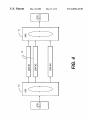
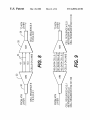
FIG. 4 shoWs hoW the ATM cells are multiplexed and then
demultiplexed over AIMs in one direction. At the transmit
ting node, an AIM 10 takes a series of ATM cells from an
“01101010”, Which is the same as that of the idle cell
as proposed in ITU Recommendation 1.361.
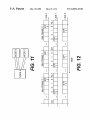
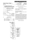
Referring to FIG. 8, the ATM inverse multiplexing pro
ATM layer device. It spreads ATM cells and transmits each
cell over each of N transmission links, N being a positive
integer. The order of transmission is in round robin fashion.
This process is called an inverse multiplexing. At the receiv
tocol according to one embodiment is described in detail
beloW. The ?gure only shoWs one direction for clarity. It is
shoWn that transmission links are all Tl/El links but, of
25
ing node, cells from N links are inverse demultiplexed
proper sequence of cells. Both nodes must be aWare of the
round robin order Which is to be employed. Upon
initialiZation, therefore, both AIMs send a series of SN cells
in round robin fashion over the links, e.g. Tl/El links. This
alloWs the receiver AIM at both nodes to establish the
transmission to a receiving node 26. An AIM at the receiving
node reassembles ATM data cells received from the links in
proper order and sends them to the ATM layer.
Link Start-up
Upon connection start-up, AIMs at both nodes start insert
35
to be transmitted on the virtual link (composed of N physical
links). HoWever, the sequence number is only carried over
the SN cells. This sequence number assignment alloWs the
receiving AIM to retrieve the original cell sequence. The
receiving node queues the received AIM SN cells until it
to the same link round robin. This information can then be
used locally to determine if at the corresponding local node
a link should be added, removed or maintained in the round
robin.
When a change of link con?guration occurs by a link
being added, removed or declared as being doWn, each node
sends a series of SN cells to alloW the far-end node to
45
OAM cell that is de?ned to be exclusively processed by the
determines the sequence in Which to read the ATM data cells
from the incoming links as Well as the differential delay
among individual links. Then, it starts sending AIM SN cells
of its oWn, With the AIMFERR ?eld set to “one” for each
link Which is noW considered “ready” to receive ATM traf?c.
From that moment, the receiving node knoWs the sequence
of cells coming from the links. A link is being considered
available if cells are currently delineated and AIM-RDI is
ATM inverse multiplexers. The neW cell structure has to be
consistent With the cell structure de?ned in ITU Recom
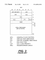
mendation 1.361. FIG. 3 shoWs that structure of UN1/NN1
ATM cells that is de?ned in 1.361. ITU Recommendations
1.361 and 1.432 state that ATM cells consisting of a header
not received on the incoming link.
When the transmitting node starts sending the AIM SN
cells, it starts a time-out of 100 milliseconds Within Which
Whose VPI and VCI ?elds are set to Zero are reserved for use
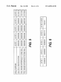
by the physical layer. So far three preassigned values of the
ing AIM OAM cells (AIM SN cells) carrying cell sequence
number over the available links in round robin fashion. The
sequencing of cells is based on the order in Which cells have
used by each Tl/El link to indicate that both AIMs belong
reestablish the sequence of cells to read from the incoming
links.
The protocol of the invention calls for a physical layer
course, links can have a different speed from Tl/El, as long
as all the links have the same speed. A transmitting node 20
collects digital data consisting of a series of ATM data cells
from the ATM layer. An ATM inverse multiplexer (AIM) at
the transmitting node spreads over multiple links 24 for
(assembled) and sent to an ATM layer device by an AIM 14.
The same order must be employed at this node to recover a
sequence in Which to read cells from the incoming links as
Well as to adjust relative link delay.
As mentioned above, the SN cell also carries an extra ?eld
Cell error control (CEC)—is used to detect errors in the
55
the receiving node determines the sequence of AIM SN cells
Which it is receiving from the links. The time-out expires
cell header are reserved for use by the physical layer. They
unless the transmitting node receives the “ready” signal
are shoWn in FIG. 5.
from all the links Which Were considered available at the
The physical layer OAM cell according to one embodi
ment of the invention is then de?ned by using a non
assigned value by setting the PT ?eld to “111” or some such
code. This is shoWn in FIG. 6.
The A1M OAM cell payload is then available for
initialiZation.
If there is no “ready” link When the time-out expires, the
local node reevaluates the availability of the links (using cell
delineation), starts sending AIM SN cells over the available
links and re-starts the time-out This procedure is repeated
exchanging information betWeen AIMs. The cell payload
until at least one available link is declared ready.
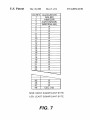
consists of a series of ?elds Whose locations are shoWn in
When the time-out has been cancelled due to the reception
FIG. 7.
65 of the “ready” signal from all the available links, or When
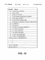
The folloWing ?elds are identi?ed for the AIM protocol
according to one embodiment of the invention:
there is at least one link ready When the time-out expires, the
local end starts sending ATM layer cells over the “ready”