1
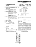
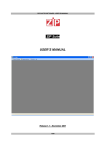
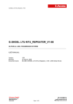
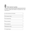
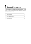
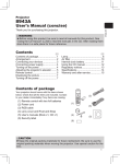
XC-E6TCA-P Temperature control module User’s manual Xinje Electronic Co., Ltd. Catalog 1. Summarization .............................................................................................................................. 3 1.1 Introduction ......................................................................................................................... 3 1.2 Features ............................................................................................................................... 3 1.3 Using requirements ............................................................................................................. 3 2 PID self-study introduction ............................................................................................................ 3 2.1 PID knowledge .................................................................................................................... 3 2.1.1 PID function ............................................................................................................. 3 2.1.2 PID parameter .......................................................................................................... 4 2.1.3 PID control characteristic ......................................................................................... 5 2.2 Self-study knowledge .......................................................................................................... 5 3 Module specs and parameters ........................................................................................................ 6 3.1 Dimension and function ...................................................................................................... 6 3.2 I/O points ......................................................................................................................... 7 3.3 Module configuration .......................................................................................................... 7 3.4 Installation steps and environment ...................................................................................... 8 4 Module address ............................................................................................................................ 10 4.1 Work mode ........................................................................................................................ 10 4.2 Module data address.......................................................................................................... 10 4.2 Related address definition ................................................................................................. 12 5. Module work process and principle ............................................................................................ 14 6. Write and read instructions.......................................................................................................... 16 6.1 Instruction explanation ...................................................................................................... 16 6.2 Instruction application....................................................................................................... 17 7. Application example ................................................................................................................... 22 1. Summarization 1.1 Introduction XC-E6TCA-P is temperature control module. As the expansion module of PLC, it has 6 channels temperature signal input and support various types thermocouple. Each channel can self-study PID parameters and communicate with PLC. So based on this module, you can build your temperature control system with PLC, LCD screen and computer. 1.2 Features Support various types of thermocouple: K, J, S, E, N, T, R. DC-DC power supply isolated design, enhance the anti-jamming ability of the system Temperature display precision 0.1℃ Each channel has independent PID parameters PID self-study under cooling, heating, transforming status FROM and TO instructions to communicate with PLC, enlarge the data storage space. 1.3 Using requirements PLC: hardware version 3.1e and above XCPpro software: version 3.1b and above Temperature sensor type: thermocouple K, S, E, N, J, T, R The measurement temperature should be higher than the module working temperature! 2 PID self-study introduction 2.1 PID knowledge 2.1.1 PID function The most applied adjuster control rule is proportion-integral-differential control which is called PID for short in engineering field. PID controller has 70 years history since it is came out. It has become one of the main industry control technologies because of its simple constitution, good reliability and stability and adjustable facility. We can use PID control technology under the following four conditions: the constitution and parameter of the control system are not commanded, can not get the precise mathematics model, other control technologies are unable to adopt, the constitution and parameter of the system controller only can be confirmed by experience and spot debug. It means the PID control technology is the most suitable way when the system or objective are unknown or unable to get the system parameters via effective measure method. PID controller calculates the control parameters according to system value differences based on proportion, integral, differential count. XINJE PID control products are widely used and have high flexibility. There are only four parameters which need to be set: Kp, Ki, Kd, Diff. PID control rule is as below: + proportion r(t) e(t) + + u(t) integral c(t) Controlled objective _ Differential + PID control system principle figure e(t) = r ( t ) –c ( t ) (1-1) u(t) = Kp [ e ( t ) + 1/Ti∫e(t)dt + TD d[e(t)]/dt] (1-2) e(t) is the windage, r(t) is the given value, c(t) is the actual value, u(t) is the control value In formula (1-2), Kp is proportion coefficient, Ti is integral time coefficient, TD is differential time coefficient. 2.1.2 PID parameter The functions of proportion parameter Kp, integral parameter Ki, differential parameter Kd, PID operation area Diff are as below: Kp: Reflect the windage of system, control is carried out to reduce the windage once it appears. Ki: Be used to clear the still difference and improve the non-difference of system. Kd: Be used to control the change trend of the signal, reduce the system oscillation. Diff: To do PID control in defined area. Death: Death area parameter. Compared the current PID output with former PID output value, if the minus value is less than the death area value, the module will abnegate the current value and output the former PID value. 2.1.3 PID control characteristic The PID control is like this way: when measure value is less than QD-Diff, the controller full-scale outputs; when measure value is more than QD+Diff, the controller stops outputing; when it is among the area of ( QD-Diff, QD+Diff ), the controller does the PID adjustment. PID control curve: Reference value: Kp=20~100; Ki=5~20; Kd=200~800; DIFF=100~200. 2.2 Self-study knowledge If the user does not know how to set the PID parameters, they can choose self-study mode which makes the system to find the optimal parameters automatically ( sampling time, Kp, Ti, TD ). 3 Module specs and parameters 3.1 Dimension and function The function of each part: Name Function Power indication The light is on when power on Module type The type of this module Expansion port Connect with other module I/O points Connect with analog I/O and exterior device, enable to tear down DIN rail pothook For installation, pull down the pothook when tear down Mounting hole Use M3 screw for installation Expansion cable Use the cable to connect the module with PLC General specs: Item Specs Environment No causticity gas Environment temperature 0℃~60℃ Conservation temperature -20~70℃ Environment humidity 5~95% Conservation humidity 5~95% Measure temperature range 0℃ ~ 1000℃ Temperature signal input channel 6 channels Resolution 0.1℃ Integrated precision 0.1℃ Transform speed 20ms per channel Fix the module with M3 screw or assemble it on DIN46227 rail Installation ( Width 35mm ) Outline dimension 3.2 63mm×102mm×73.3mm I/O points The I/O points of XC-E6TCA-P are as below: 24V TCO- 0V . COM0 .Y0 COM1 COM2 Y2 Y1 . Input points (TC0+,TC0,…,TC5+,TC5-) (Y0~Y5) Y4 Y5 TC0+ TC1+ TC2+_ TC3+ TC4+ TC5+ TC1TC2TC3TC4TC5- Name Output points Y3 Note 6 channels 6 channels Analog input: thermocouple temperature sensor Range: 0℃~1000℃ Analog output Digital form: 0~4095 On-off output Mark-space ratio form: Y point output when put through 3.3 Module configuration XC series PID control module can fix on the right side of XC series PLC, expansion units, special module. XINJE PLC can extend 7 modules and 1 BD board. The type can be I/O on-off quantity, analog quantity, temperature control module, etc. 3.4 Installation steps and environment 1. Preparation Prepare for the module installation 2. Check the installation environment Check whether the environment is suitable for installation 3. Installation Install the module on the right side of the PLC 4. Debug Check whether the module is installed correctly (1) Do not install the module under below environment: Installation request: Please install the module on DIN46277 rail ( width 35mm ) or use M3 screw to fix the module. Attention: Confirm the type and choose the suitable module. Do not let the iron or wire bits drop into the module. Confirm the module type again before installation. Make sure the connection is stable, if the wire is loose the data will be incorrect and result in circuit shorting. Make sure the power is cut off for installation and layout 4 Module address 4.1 Work mode XC-E6TCA-P can connect with various types of thermocouple. In order to configure them, we give a number for each type: No. 1 Sensor type 2 K S 3 E 4 5 N J 6 T 7 R To choose the thermocouple type for each channel, you should set the data in FD8250 and FD8251 of PLC. FD8250 channel 1 Bit7 Bit6 Bit5 channel 0 Bit4 Write type NO. Bit3 Bit1 Bit0 Write type NO. channel 3 Bit15 Bit2 Bit14 Bit13 channel 2 Bit12 Write type NO. Bit11 Bit10 Bit9 Bit8 Write type NO. FD8251: channel 5 Bit7 Bit6 Bit5 channel 4 Bit4 Write type NO. Bit3 Bit2 Bit14 Bit0 Write type NO. / Bit15 Bit1 / Bit13 Bit12 Bit11 Bit10 Bit9 Bit8 For example: channel 0 is type K(No.1), channel 1 is type E(No.3), channel 5 is type S(No.2), so FD8250=31H, FD8251=20H. 4.2 Module data address Parameters Explanation Channel Ch0 Ch1 Ch5 Module 1 ID100 ID101 ID10× ID105 Module 2 ID200 ID201 ID20× ID205 ID×00 ID×01 ID×0× ID×05 Module 7 ID700 ID701 ID70× ID705 Module 1 X100 X101 X10× X105 Module 2 X200 X201 X20× X205 X×00 X×01 X×0× X×05 Module 7 X700 X701 X70× X705 Connection state Module 1 X110 X111 X11× X115 of Module 2 X210 X211 X21× X215 thermocouple(0 is X×10 X×11 X×1× X×15 connection, 1 is Module 7 X710 X711 X71× X715 Module 1 Y100 Y101 Y10× Y105 Module 2 Y200 Y201 Y20× Y205 Y×00 Y×01 Y×0× Y×05 Module 7 Y700 Y701 Y70× Y705 self-study Module 1 X120 X121 X12x X125 error signal bit(0 Module 2 X220 X221 X22x X225 is normal, 1 is ….. Xx20 Xx21 Xx2x Xx25 error) Module 7 X720 X721 X72x X725 Display temperature Unit: 0.1 ℃ PID output ( return to the X input of PLC ) cut connection) Enable signal PID self-study triggered signal, enter into self-study mode when setting 1. self-study PID control bit After ending self-study, PID parameters and temperature control period value are refreshed, the bit value is cleared to be 0. The user can read the bit to know the state. 1 means self-study is ongoing. 0 means self-study has ended. Digital quantity output range is 0~4095. PID output When the PID output is analog quantity (steam valve open degree or silicon-controlled ( The result ) conduction angle ), the value can be transmitted to the analog quantity output module in order to realize the control demand. PID parameters ( P, I, D ) PID calculation The best PID parameters got from the PID self-study. If the current PID parameters can not meet the control requirements, users can set the experience PID parameters to make the module work according to the user setting value. PID arithmetic is effective in the range of T (setting temperature) ±Diff. In real temperature range ( Diff ) control environment, when the temperature is lower than T- Diff, the PID output is the maximum Unit: 0.1℃ value; when the temperature is higher than T+Diff, the PID output is the minimum value. Temperature difference value δ Unit: 0.1℃ Set temperature ( sampling temperature value + temperature difference value δ ) / 10 = display temperature. At the time the display temperature is the most close to the real temperature. This parameter is a sign value with the unit of 0.1℃, the value is retained when th power is cut off, the defaulted value is 0. The target temperature of the control system. Range from 0~1000℃, precision degree is 0.1℃. Unit: 0.1℃ Temperature The temperature control period range from 0.5 to 200 seconds, the minimum precision is 0.1 control period second. The set value = real value × 10. For example: if the real temperature control period is Unit: 0.1s 0.5 seconds, user should set 5 seconds in the module. If user realizes that the environment temperature is different from display temperature, they can write the correct environment temperature into the module. Then the module will calculate the temperature difference δ and save it. Temperature difference δ = adjusting environment temperature-sampling temperature. Unit: Adjusting 0.1℃. For example, under the caloric balance condition, users measured the environment environment temperature is 60℃ with mercury thermometer, but the display temperature is 55℃ ( sampling temperature temperature is 550 ), temperature difference δ is 0. At this time, users can set the parameter to be Unit: 0.1℃ 600, then the temperature difference δ is 50 ( 5 ºC ). Display temperature = ( 550 + 50 ) / 10 = 60 ºC. **Attention: when setting the adjusting environment temperature, make sure it is the same as environment temperature. It is very important because the incorrect parameter will result in mistake of calculating temperature difference δ and affect the display temperature. self-study output The self-study output unit is percent. 100 means the mark-space ratio is 100% of the full-scale range output, 80 means the mark-space ratio is 80% of the full-scale output. 4.2 Related address definition When using the module, it needs to write and read the parameters, the parameters' address are as below: 1. Read instruction: FROM The operating objective address: Address Description K0 Self-study PID control state signal K1 Ch0 PID output K2 Ch1 PID output : : Ch5 PID output : K6 K7 K8 K9 PID parameter P Ch0 PID parameter I PID parameter D K10 PID parameter Diff K11 PID parameter P K12 K13 Ch1 K14 : PID parameter I PID parameter D PID parameter Diff : : K27 PID parameter P K28 PID parameter I Ch5 K29 PID parameter D K30 PID parameter Diff K31 Ch0 K32 Ch1 : : K36 Ch5 Temperature difference value Temperature difference value : Temperature difference value 2. Write instruction: TO The operating objective address: Address Description K0 Self-study PID trigger signal K1 Ch0 Setting temperature K2 Ch1 Setting temperature : K6 : Ch5 K7 K8 K9 : Setting temperature PID parameter P Ch0 PID parameter I PID parameter D K10 PID parameter Diff K11 PID parameter P K12 K13 Ch1 K14 : PID parameter I PID parameter D PID parameter Diff : K27 : PID parameter P K28 PID parameter I Ch5 K29 PID parameter D K30 PID parameter Diff K31 Ch0 Temperature control period K32 Ch1 Temperature control period : : K36 Ch5 Temperature control period K37 Ch0 Adjusting environment temperature K38 Ch1 Adjusting environment temperature : : K42 Ch5 Adjusting environment temperature K43 Ch0 Self-study output range K44 Ch1 Self-study output range : : : : : K48 Ch5 Self-study output range The module can save the parameters which include temperature, PID parameters ( P, I, D, Diff... ), temperature difference value, temperature control period, self-study output range, etc. The module will save the parameters after self-study finishing or user modifying then take out them to do related operations when rebooting. The module's defaulted value of the parameters when leaving factory: Parameter Setting temperature ( ºC ) PID parameters Defaulted value CH0 CH1 CH2 CH3 CH4 CH5 0 0 0 0 0 0 P 40 40 40 40 40 40 I 1200 1200 1200 1200 1200 1200 D 300 300 300 300 300 300 Diff 10 10 10 10 10 10 20 20 20 20 20 20 0 0 0 0 0 0 100 100 100 100 100 100 Temperature control period ( unit: 0.1s ) Temperature difference ( Sign value ) self-study output range 5. Module work process and principle The module work process is as below: When the module power on, it reads the PID parameters, target temperature, temperature control period, self-study output range. So even the module power off and power on again, these parameter will still be kept. PID parameters set by user PID parameters modified by module after self-study Setting temperature, temperature control period, temperature difference value, self-study output range ( set value or defaulted value ) Write into Flash-ROM, read them out when the module power on After power on and read all the parameters, the module starts to collect the temperature. Then write the target temperature, temperature control period, self-study output range into the module. The module judges the enable signal of each channel, if the signal is ON, it starts the PID control for the object. Meanwhile, the module will judge if there is self-study trigger signal. If the trigger signal is ON, when the rise edge coming, the self-study process will begin and the state bit will be set ON; when the self-study process is completed, state bit and trigger signal will be set OFF; then the module enter into PID control. If the self-study trigger signal is not ON, the module will keep doing PID control. Pay attention to this: The module does PID control process according to PID parameters, target temperature, temperature control period. If the temperature control period is 0, this channel will not output and only collect temperature. The control process chart is as below: No The module power on Collect temperature Channel enable bit is ON? Yes PID control No No Self-study trigger signal is ON? Yes Self-study control Self-study process ends, self-study control bit will be set OFF 6. Write and read instructions 6.1 Instruction explanation PLC can read and write parameters of XC-E6TCA-P via FROM and TO instruction. 1. Read instruction: FROM This instruction can read the data from the module. It can divide into bit and word operation. (1) word operation Function: read the data of the module and save them in PLC register, object operand unit is word. Operand explanation: S1: target module number. Operand: K, TD, CD, D, FD. S2: the data head address of the module. Operand: K, TD, CD, D, FD. S3: the register quantity ( how many words ). Operand: K, TD, CD, D, FD. D1: the register head address of the PLC. (2) bit operation Function: read the data of the module and save them in PLC coil, object operand unit is bit. Operand explanation: S1: target module number. Operand: K, TD, CD, D, FD. S2: the data head address of the module. Operand: K, TD, CD, D, FD. S3: the data quantity ( how many bits ). Operand: K, TD, CD, D, FD. D1: the coil head address of the PLC. Operand: M, Dn.m. 2. Write instruction: TO This instruction can write the data to the module. It can divide into bit and word operation. (1) word operation Function: write the data of PLC register to the module, object operand unit is word. Operand explanation: D1: target module number. Operand: K, TD, CD, D, FD. D2: the head address of the module. Operand: K, TD, CD, D, FD. D3: the register quantity ( how many words ). Operand: K, TD, CD, D, FD. S1: the register head address of the PLC. (2) bit operation Function: write the data of PLC coil to the module, object operand unit is bit. Operand explanation: D1: target module number. Operand: K, TD, CD, D, FD. D2: the head address of the module. Operand: K, TD, CD, D, FD. D3: the data quantity ( how many bits ). Operand: K, TD, CD, D, FD. S1: the coil head address of the PLC. Operand: M, Dn.m. 6.2 Instruction application 1. Set the target temperature Explanation: PLC register D0 module address K1 First save target temperature in D0, when set on M1, the data of D0 will write to module address K1( channel 0 set temperature ). D0=200 means the target temperature is 200 ºC. Operand meaning: TO: write instruction K0: the module number is 0 K1: the data address in the module K1: write word quantity is 1 word D0: the PLC register saved the data 2. Set the temperature control period Explanation: PLC register D10 module address K31 Write the temperature control period ( D10 ) to module channel 0 ( K31 ) when M1 is set on. D10 = 25 means the temperature control period is 2.5 seconds. Operand meaning: TO: write instruction K0: module number is 0 K31: the data address in the module K1: word quantity is 1 word D10: the PLC register saved the data 3. Self-study output range Explanation: PLC register D20 module address K43 Write the self-study output range ( D20 ) to module channel 0 ( K43 ) when M1 is set on. D20 = 80 means the self-study output range is 80% of the full-scale. Operand meaning: TO: write instruction K0: module number is 0 K43: the data address in the module K1: write word quantity is 1 word D20: the PLC register saved the data 4. Set on the self-study trigger bit Explanation: PLC coil M0 M1 M2 M3 M4 M5 module address K0 bit 0 K0 bit 1 K0 bit 2 K0 bit 3 K0 bit 4 K0 bit 5 Write M0~M5 to the module address K0 when M100 is set on. If M0 = 1, start the self-study process of channel 0. If M1 = 1, start the self-study process of channel 1...... Operand meaning: TO: write instruction K0: module number is 0 K0: the data address in the module K6: the write bit quantity is 6 bits M0: the head address of the data in the PLC. 5. Read the self-study state bit Explanation: PLC coil M10 M11 M12 M13 M14 M15 module address K0 bit 0 K0 bit 1 K0 bit 2 K0 bit 3 K0 bit 4 K0 bit 5 read self-study state bit of every channel and save them in M10~M15. If M10 is ON, then channel 0 is doing self-study; if M10 is OFF, the self-study process is completed or never begins. If M11 is ON, the channel 1 is doing self-study....... Operand meaning: FROM: read instruction K0: the module number is 0 K0: the data address in the module K6: read bit quantity is 6 bits M10: the head address of the data saved in the PLC 6. Read PID parameters Explanation: PLC register D30 D31 D32 D33 module address K7 K8 K9 K10 read the PID parameters (channel 0) and save them in D30~D33 of the PLC. D30 = P, D31 = I, D32 = D, D33 = Diff parameter. Operand meaning: FROM: read instruction K0: the module number is 0 K7: the data address of the module K4: read word quantity is 4 words D30: the head address of the data saved in the PLC 7. Write the PID parameters Explanation: PLC register D40 D41 D42 D43 module address K27 K28 K29 K30 Users can save the PID parameters in D40~D43 then write them to the module channel 5. Operand meaning: TO: write instruction K0: the module number is 0 K27: the data address in the module K4: write word quantity is 4 words D40: the head address of the data saved in the PLC 8. Open the enable bit signal Explanation: For module number one, channel 0~5 are corresponding to Y100~Y105; for module number two, channel 0~5 are corresponding to Y200~Y205....... So set on the corresponding enable bit to start the PID control for the channel. 9. Read PID output Explanation: PLC register D50 D51 D52 D53 D54 D55 module address K1 K2 K3 K4 K5 K6 During PID control process, users can read PID output of every channel and save them in D50~D55. Operand meaning: FROM: read instruction K0: the module number is 0 K1: data address in the module K6: read word quantity is 6 words D50: the head address of data in the PLC 7. Application example For this example, we will control 5 channels of temperature by using XC-6TCA-P. The whole control system includes TP series HMI, XC series PLC, XC-6TCA-P, K type thermocouple, heating resistor and other devices. The system chart is shown as following: PLC HMI K type thermocouple XC-E6TCA-P Heating resistor Target object The control processes are as the following: 1. Power on the XC-6TCA-P to read the current temperature, display them on the HMI. 2. Write the target temperature, turn on “write target temperature” button on the HMI, the value will be written into XC-6TCA-P. 3. If user wants to modify the default PID parameters, input the PID value and turn on “PID enable bit” button on the HMI, XC-6TCA-P will enter PID control process. 4. If XC-6TCA-P needs to self-study, turn on the “self-study state bit” then turn on “self-study control bit” on the HMI to start the self-study process. 5. To monitor the “self-study state bit”, you can see if the self-study process is over. 6. Turn on “read PID parameters” to read the PID parameters of each channel. 7. If you want to adjust the ambient temperature, push the “adjust ambient temperature” button to enter the adjustment screen. First of all, set the thermocouple types in the XCPpro software. As the 0~4 channels are K type thermocouple, set FD8250 to 1111H, FD8251 to 01H. Next, please see the corresponding address of PLC and XC-6TCA-P. PLC M10-M14 M100-M104 D4000-D4004 D4050-D4069 D10-D14 XC-6TCA-P K0 Y100-Y104 K1-K5 K7-K26 K37-K40 Remark Self-study enable bit 0~4 channel PID enable bit 0~4 channel target temperature 0~4 channel P,I,D,DIFF values 0~4 channel adjustment temperature The HMI screens are as the following: M1 M100~M104 M10~M14 M2 M3 M6 M5 The ladder chart: M1 TO K0 D4000 Write channel 0~4 target temperature into XC-6TCA-P address K1~K5 MOV D4010 D4053 Move the value of D4010 to D4053, (channel 0 DIFF value) MOV D4010 D4057 Move the value of D4010 to D4057, (channel 1 DIFF value) MOV D4010 D4061 Move the value of D4010 to D4061, (channel 2 DIFF value) MOV D4010 D4065 Move the value of D4010 to D4065, (channel 3 DIFF value) MOV D4010 D4069 Move the value of D4010 to D4069, (channel 4 DIFF value) K7 K20 D4050 Write the value of D4050-D4069 into K7-K26,(channel 0~4 P,I,D,DIFF value) K1 K5 M2 TO K0 M5 FMOV TO K0 D4020 D10 K5 Write the value of D4020 to D10-D14, (ambient temperature) K37 K5 D10 Write the value of D10-D14 to K37-K41, (channel 0~4 adjust ambient temperature) M6 S0 ( M10 M11 M12 M13 M14 S0 S ) M100 ( S ) M101 ( S ) Set on M6 to enter process S0; Set on M100 when M10 is on Set on M101 when M11 is on M102 ( S ) Set on M102 when M12 is on M103 ( S ) Set on M103 when M13 is on M104 ( S ) Set on M104 when M14 is on STL S0 S0 M4 T0 ( K5 ) Process S0 is on, delay 5ms T0 M4 TO K0 K0 M10 K5 M4 ( S ) Write the value of M10~M14 to K0 (self-study trigger bit) M4 is self-study process sign bit M4 M8013 FROM K0 K0 M10 M11 M12 M13 M14 T1 ( T1 M10 K5 K5 ) M4 ( R ) Read the value of K0 to M10~M14 every 1s, to see if the self-study process has been finished. If the self-study has been finished or never begun, delay 5ms After 5ms, reset M4. S0 ( R ) Reset process S0 K20 D4050 Read the P, I, D, DIFF value of channel 0~4 STLE M3 FROM K0 K7 M4 M8012 M100 M101 M102 M103 M104 Read the P, I, D, DIFF value every 100ms Y100 ( ) Open channel 0 PID control bit Y101 ( ) Open channel 1 PID control bit Y102 ( ) Open channel 2 PID control bit Y103 ( ) Open channel 3 PID control bit Y104 ( ) Open channel 4 PID control bit