1
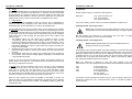
USER MANUAL
LEDCON43
DMX RGB LED Controller
ENGLISH Page 2-12
RevA 11/2009 Order code: 12-015-0083-80100-1-01
User Manual: LEDCon43
■ Introduction
Dear customer,
congratulations on the purchase of this quality item and the trust having been put in us
with this decision. To take full advantage of all possibilities and for your own safety and
the safety of your environment, please read these operating instructions carefully
before you start using the unit.
■ Security advice before use
Warning: Read this section carefully before installing, powering,
operating, cleaning or servicing this product!
The following symbols are used to identify important safety information in this manual:
DANGER!
Safety hazard.
Risk of injury or
death.
WARNING!
Hazardous
voltage. Risk of
severe or fatal
electric shock.
WARNING!
Fire hazard.
WARNING!
Read manual
before installation
and operation.
General advice:
1. Read this manual completely before using the product.
2. Keep this manual in your records for future reference.
3. Follow all instruction printed in this manual, otherwise warranty
may be void.
4. Follow all printed security advice on the product itself. The lighting
flash with arrowhead within an equilateral triangle makes you
aware of non-insulated AC mains voltage inside the unit. The
exclamation mark within an equilateral triangle makes you aware of
important operating and maintenance instructions in the literature
attached to this product.
5. Take care of enough distance between this product and sources of
hum and noise like electric motors and transformers.
6. Carry this product with greatest care. Punches, big forces and
heavy vibration may damage this product mechanically.
7. The manufacturer takes no responsibility for injury or damage
caused by not following the safety precautions and instructions
printed in this manual.
V1.00 (11-2009)
2
User Manual: LEDCon43
Protection from electric shock:
1. Only connect this unit or its power supply to a mains socket outlet
with protective earth connection, ground-fault (earth-fault)
protection and overload protection.
2. Where the mains plug or an appliance coupler is used as a disconnect device, the disconnect device shall remain readily
operable.
3. To pull the power supply out of the wall outlet, never pull the cable,
but only the power supply itself.
4. Disconnect the unit from AC supply by pulling the power supply out
of the wall outlet before any kind of cleaning on the product. Use
smooth and dry cloth only for cleaning. Check all connection cables
before reconnecting the unit.
5. Do not expose this unit or its power supply to any dripping or
splashing liquids, and do not place objects filled with liquids, such
as vases, on the unit or its power supply. Do not operate this unit
near to open water or in high humidity.
6. Choose the position of the power supply and the connection cords
according to the lowest risk of damage by foot steps or by
squeezing it.
7. Do not open the unit or its power supply for service purpose, as
there are no user-serviceable parts inside. Warranty will be void in
any case of unauthorized service by the user or other not
authorized persons.
Protection from fire:
1. Take care of not placing the unit or its power supply near sources
of heat (e.g. powerful amplifiers, fog machines).
2. Take always care of sufficient air convection in the unit’s and its
power supply’s environment to avoid overheating, especially when
mounting in a closed environment. Make sure air convection slots
are not blocked. Do not operate this unit in environmental
temperatures exceeding 40 degrees Celsius.
3. Check the total maximum power of your AC wall outlet if you
connect several units to one wall outlet and avoid any overloading.
Protection from injury and damage:
1. Never use any accessories or modifications not authorized by the
manufacturer of this unit.
2. Choose a location for operation where the unit is protected from
vibration and where a fixed position is provided.
3. Before plugging the power supply in the wall outlet, check whether
the AC mains voltage and frequency is the same as this product is
specified for. Whenever your power supply should not match the
wall outlet, contact you dealer immediately.
4. If fluids have spilled into the unit or its power supply, or small parts
V1.00 (11-2009)
3
User Manual: LEDCon43
5.
6.
7.
User Manual: LEDCon43
have intruded the unit or its power supply, immediately switch off
the unit and hand it over to the authorized service for a security
check.
Disconnect the unit from AC supply by pulling the power supply out
of the wall outlet during a thunder-storm in order to avoid any
damage on the unit or its power supply due to AC voltage peaks.
In cause of not correct function of this unit or damaged power
supply or other damaged parts, pull immediately the power supply
out of the wall outlet and hand the unit over to the authorized
service for a security check.
To meet all aspects of functionality and security during maintenance work to be performed on this unit, all parts should be
replaced by genuine spare parts. Consequently, take care of your
dealer or maintenance company to be authorized by the
manufacturer.
■ Health advice
This unit produces and absorbs electromagnetic radiation. The strength of radiation and
the sensitivity for disturbing interference matches the CE and FCC requirements. A
corresponding sign is printed on the backside of the unit. Any change or modification
may affect the behavior of the unit concerning electromagnetic radiation, with the CE
requirements eventually not to be met any more. The manufacturer takes no
responsibility in this case.
■ Functional advice
This unit is immune to the presence of electromagnetic disturbances – both conducted
and radiated - up to a certain level. Under peak conditions, the unit is classified to show
a “class C” performance criteria and may encounter temporary degradation or loss of
function which may need manual help to recover. In such case, disconnect the AC
power from the unit and reconnect it again to recover.
■ Switch-on condition
Every time the unit is switched on, it is in following status:
BLACK OUT = ON
DIM = 100%
PATTERN = 00
STROBE OFF
TRS = SWITCH
COLOR = 00
MODE = PATTERN
TAP = S2L
■ Maintenance
This unit does not need regular maintenance. If this unit fails, this usually indicates an
internal fault requiring servicing by a qualified engineer. In such case, please seek
assistance from your dealer/installer.
■ Technical data & Compliance LEDCon43 DMX LED controller:
Power supply……………..…………12V DC by 85-240V AC / 50-60Hz / 100mA adaptor
Control protocol.......................................................................................DMX 512 (1990)
Dimensions………………………………………………………....W 70 x H 110 x D 33 mm
Weight ……………………………………………………………………………………0,31 kg
This product complies with the following standards:
EU safety...........................................................................................EN 60065:2001 +A1
EU EMC................................................................... EN55103-1:1997, EN55103-2: 1997
US safety ………….…………..………………………………………………………UL60065
US EMC………………………..…………………………………………………..FCC Part 15
This product meets both the EMC Directive 2004/108/EC and the Low Voltage Directive
2006/95/EC.
■ Environmental advice
This unit is build to conform to the ROHS standards and the WEEE
directive 2002/96/EC of the European Parliament and of the Council of
the European Union. Under these regulations, the product shall not be
discarded into regular garbage at the end of its life, but shall be returned
to authorized recycling stations.
V1.00 (11-2009)
4
V1.00 (11-2009)
9
User Manual: LEDCon43
User Manual: LEDCon43
B. Strobe
Pressing the STROBE button (10) activates the strobe mode with all spots flashing
in white (C13) at a fixed rate of 16 flashes/sec. It overrides any other mode (apart
from the BLACK OUT mode), but does not cancel the settings of that mode. The
DIMMER setting also affects the strobe mode, but is global and not memorized
independently. A LED is used to indicate that the STROBE mode is active.
C. Pattern/Scene
When BLACKOUT and STROBE are both off, then the unit is automatically in
Pattern or Scene mode, depending on the users choice, which is determined by
the MODE button (8) and indicated by one LED for the SCENE mode.
In PATTERN mode, the unit plays a pattern which can be combined from a pattern
structure chosen with the PTN button (7) [10 choices to step through] and a color
setting chosen with COL button (11) [8 choices to step through]. The dimming level
in PATTERN mode can be chosen with the DIM button (5) [3 visual perception
levels 50/75/100% to step through] and the speed can be set in either of the
following ways:
1. TAP TEMPO: When the TAP button (12) is pressed at least 4 times
consecutively with less than 1s time elapsed between two taps, then the
average time distance between the taps is used for the speed setting. This is
useful to align the pattern speed with music playing. Note: if more than 1s of
time elapses between two taps, the speed mode may change to SOUND-TOLIGHT or SLOW MODE.
2. SOUND-TO-LIGHT: When the TAP button (12) is pressed once, then the
internal microphone signal is used for sound-to-light control and the respective
LED is lit.
3. SLOW MODE: When the TAP button (12) is pressed twice, then the speed is
set to 3s/step. This is useful for display lighting, especially in combination with
a soft TRANSITION setting.
Further, it can be set via the TRS switch (6) whether the transition between the
pattern steps is a hard switch or a soft fade (50% of the set speed cycle for fade up
and down); a LED shows the choice.
■ Unpacking
Please check that the box contains the following items:
Main parts:
1 pcs. LEDCon43 main unit
1 pcs. power adaptor
1 pcs. operation manual
If any part is missing, please contact your dealer immediately for replacement.
■ Getting started: choosing a location
Risk of fire: The LEDCon43 has been designed to work in dry indoor
environments at environmental temperatures up to 40 degrees Celsius.
Do not operate the LEDCon43 in environments with more than 40 degrees
environmental temperature or more than 80% humidity.
■ Getting started: connecting devices
Risk of electric shock: Make sure that all controlled devices are
properly connected to ground (earth).
Use standard 3-pin microphone cables with proper shielding to connect the DMX output
(4) of the LEDCon43 with the DMX input of the first controlled device. Then connect the
first device’s DMX output with the next device’s DMX input. Continue to daisy-chain the
controlled devices up to the last device. Make sure the last device’s DMX output is
terminated with a 120 Ohm DMX termination plug. Failure to terminate the DMX bus
may yield unpredictable behaviour of the system.
Note: The LEDCon43 is designed to work with other products of the same
manufacturer or any other target device which follows the below DMX channel scheme:
In SCENE mode, the unit generates a static scene. The color or color combination
of the scene can be set by the COL button (11). The dimming level in SCENE
mode can be chosen with the DIM button (5) [3 visual perception levels
50/75/100% to step through]. The speed controls (TAP button and sound-to-light)
are without influence in SCENE mode, as well as the TRS transition control; they
however can be pre-set for a later time when Scene mode is left.
CH1:
CH2:
CH3:
CH4:
When the user changes the mode from SCENE to PATTERN or reverse, the
settings for PTN, COL and SPEED are memorized, so whenever the user changes
back, the previous settings will be recalled. The DIMMER setting is global and
memorized as well.
Connection of other manufacturer’s devices may not yield a working system and may
damage the LEDCon43 or any connected device. We do not accept any liability for
such occurrence.
V1.00 (11-2009)
8
V1.00 (11-2009)
0..255 Intensity red
0..255 Intensity green
0..255 Intensity blue
0..127 Master Dimmer
128..227 Strobe
228..255 Master full on
5
User Manual: LEDCon43
User Manual: LEDCon43
■ User Interface
■ Choose a configuration
As the controller can be configured by means of the CONFIGURATION switch (3) to
cater for different target devices and geometrical setups, choose a setting based on
your rigging configuration or target device first before switching on the controller. Use
any of the following configurations or design one which matches the logic of the below
best:
1
2
3
4
5
6
7
8
9
10
11
12
13
POWER switch
DC inlet to connect AC/DC adaptor
CONFIGURATION switch (3-4 selectable)
DMX OUTPUT connector
DIMMER LEVEL selector (50/75/100%)
TRANSITION selector (hard/soft)
PATTERN selector
MODE selector (pattern/scene)
BLACKOUT button
STROBE button
COLOR scheme selector
TAP SPEED button
Microphone
V1.00 (11-2009)
■ Operation
The connected target devices will be driven according to four possible modes:
A. Black out
All spots are off. Pressing the BLACK OUT button (9) once overrides any other
mode, like STROBE and SCENE/PATTERN, but does not cancel that mode,
simply sets all dim levels instantly to zero. Pressing the BLACK OUT button (9)
again lets the unit return to any chosen mode. As the blackout function only sets
the dim levels to zero for the time it is active, all other functions remain active in the
“background”, and changes can be applied which become effective when the
blackout mode is cancelled by pressing the BLACKOUT button again. A LED
indicates when the blackout mode is active. The BLACK OUT Mode is always
active when switching the unit on.
6
V1.00 (11-2009)
7