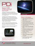
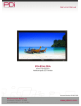
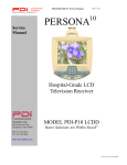
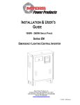
1
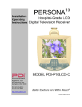
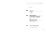
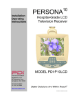
MODEL NUMBER:
Document Number:
PDI-P14W
Your Source for Healthcare and
Wellness Infotainment™
Service Manual
PD196-239R2
Page 1 of 13
This Service Manual is intended for use by qualified service persons possessing an adequate background in
electrical equipment, electronic devices, and mechanical systems. In any attempt to repair a major product, personal
injury and property damage can result. The manufacturer or seller maintains no liability for the interpretation of this
information, nor can it assume any liability in conjunction with its use. When servicing this product, under no
circumstances should the original design be modified or altered without permission from PDi. Unauthorized modifications
will not only void the warranty, but may also lead to property damage or user injury.
Copyright, Disclaimer, and Trademarks
Copyright
PDi Communication Systems, Inc. claims proprietary right to the material disclosed in this service manual. This manual is
issued in confidence for servicing information only and may not be used to manufacture anything shown herein.
Copyright 2012 by PDi Communication Systems, Inc. All rights reserved.
Disclaimer
The author and publisher have used their best efforts in preparing this manual. PDi Communication Systems, Inc. makes
no representation or warranties with respect to the accuracy or completeness of the contents of this manual and
specifically disclaim any implied warranties of merchantability or fitness for any particular purpose and shall in no event be
liable for any loss of profit or any other damages, including but not limited to special, incidental, consequential or other
damages. The information contained herein is believed accurate, but is not warranted, and is subject to change without
notice or obligation.
Trademarks
All brand names and product names used in this manual are trademarks, registered trademarks, or trade names of their
respective holders.
PDi is a registered trademark of PDi Communication Systems, Inc., Springboro, Ohio.
Dolby Digital Manufactured under license from Dolby Laboratories. “Dolby” and the double-D symbol are trademarks of
Dolby Laboratories.
Regulatory Information
FCC
This equipment has been tested and found to comply with the limits for a Class A digital device, pursuant to part 15 of the
FCC Rules. These limits are designed to provide reasonable protection against harmful interference when the equipment
is operated in a commercial environment. This equipment generates, uses, and can radiate radio frequency energy and, if
not installed and used in accordance with the instruction manual, may cause harmful interference to radio
communications. Operation of this equipment in a residential area is likely to cause harmful interference in which case the
user will be required to correct the interference at his own expense.
PDi Communication Systems, Inc. 40 Greenwood Lane Springboro, Ohio 45066 USA PH 1-800-628-9870 FX 937-743-5664
MODEL NUMBER:
Document Number:
PDI-P14W
Your Source for Healthcare and
Wellness Infotainment™
Service Manual
PD196-239R2
Page 2 of 13
Underwriters Laboratories
The model PDI-P14W TV Hospital Grade TV Receiver is a specialized television. This TV is
intended for entertainment and educational purposes for use in a hospital, a nursing home, a
medical-care center, or a similar health-care facility in which installation is limited to a non-hazardous
area in accordance with the National Electrical Code.
This device is safety tested and listed by the Underwriters Laboratories as a product suitable for use
in health care facilities in both the United States and Canada.
ESD Notice (Electrostatic Discharge)
Today’s electronics are electrostatic discharge (ESD) sensitive. ESD can weaken or damage the electronics in a manner
that renders them inoperative or reduces the time until their next failure. Connect an ESD wrist strap to a ground
connection point or unpainted metal in the product. Alternatively, you can touch your finger repeatedly to a ground
connection point or unpainted metal in the product. Before removing a replacement part from its package, touch the antistatic bag to a ground connection point or unpainted metal in the product. Handle the electronic control assembly by its
edges only. When repackaging a failed electronic control assembly in an anti-static bag, observe these same
precautions.
Product Safety Servicing Precautions
1. POWER SOURCE Use only a power source indicated for use with this product. This TV will operate on either DC or
AC voltage. To avoid personal injury, disconnect the power before servicing this product. If electrical power is
required for diagnosis or test purposes, disconnect the power immediately after performing the necessary checks.
2. REPLACEMENT Replace only with the part number specified.
3. VOLTAGE CHECKS Exercise care when making voltage and waveform checks to prevent costly short circuits from
damaging the unit.
4. METAL OBJECTS Be cautious of lost screws and other metal objects to prevent a possible short in the circuitry.
5. SAFETY CHECKS This hospital grade television requires special safety checks before returning to service. Observe
and follow the “Safety Check” section in this service manual.
6. DANGER: ARM RECOIL HAZARD The safety brake pin must remain in the SAFETY BRAKE PIN
HOLE whenever the television set is removed from the arm or when the arm is removed from the
wall bracket to prevent the arm from springing open.
PDi Communication Systems, Inc. 40 Greenwood Lane Springboro, Ohio 45066 USA PH 1-800-628-9870 FX 937-743-5664
MODEL NUMBER:
Document Number:
PDI-P14W
Your Source for Healthcare and
Wellness Infotainment™
Service Manual
PD196-239R2
Page 3 of 13
Copyright, Disclaimer, and Trademarks .................................................................................................................................. 1
Regulatory Information ............................................................................................................................................................ 1
Product Safety Servicing Precautions ..................................................................................................................................... 2
PDI-P14W Specifications ........................................................................................................................................................ 4
Disinfecting and Cleaning ....................................................................................................................................................... 5
Checking Points to Consider ................................................................................................................................................... 5
Product Identification ............................................................................................................................................................... 5
Disassembly ............................................................................................................................................................................ 6
Swivel .................................................................................................................................................................................. 6
Back Cover .......................................................................................................................................................................... 7
Speakers.............................................................................................................................................................................. 7
Board Removal .................................................................................................................................................................... 8
Parts List .............................................................................................................................................................................. 8
Test Points .............................................................................................................................................................................. 9
Power Board ........................................................................................................................................................................ 9
LED Backlight Board ......................................................................................................................................................... 10
Headphone Board ............................................................................................................................................................. 10
Basic Troubleshooting Steps ................................................................................................................................................ 11
Reassembly........................................................................................................................................................................... 12
Safety Checks ....................................................................................................................................................................... 13
PDi Communication Systems, Inc. 40 Greenwood Lane Springboro, Ohio 45066 USA PH 1-800-628-9870 FX 937-743-5664
MODEL NUMBER:
Document Number:
PDI-P14W
Your Source for Healthcare and
Wellness Infotainment™
PD196-239R2
Service Manual
Page 4 of 13
PDI-P14W Specifications
HEALTHCARE SPECIFIC AUDIO FEAT.
PANEL
Diagonal Size
HDTV compatible
Backlight Type
Display Resolution
Luminance
Contrast Ratio
14.0”
Yes
LED
1366 x 788
300 nits
500:1
45”H, 15ºV-up, 35ºVdown
8 ms
50K Hours (modified
LED Rails)
262k
Viewing Angle
Response Time
Panel Lamp Life
Color Range
TV FEATURES
Parental Control (V-CHIP)
Auto Power On
Bed A/B
Guide Menu Selection of Sources
Channel Enable/Disable
Clone Programmable (By USB)
Pro:idiom/MPEG4
FM Tuner
2D digital Comb Filter
3:2 Pull Down Compensation
Channel
Menu OSD
Progressive Scan
Antenna Input-Coax
Factory Reset
Selectable Pillow Speaker
Universal Pillow Speaker Recognition
Programmable Source Selection by Naming
Sleep Timer
Aspect Ratio Control
Keypad
Keypad Backlight
Hand Grip
Protective Panel
Yes
Yes
Yes
Yes
Yes
Yes
Yes
Yes
Yes
Yes
All channels for ATSC
and NTSC
English/French/Spanish
Yes
1(75ohm Unbalanced
Female F)
Yes
No
No
No
Yes, using remote
16:9, 14:9, 4:3, 16:9
Panoramic
Capacitive Touch
Yes, with adjustable
brightness
Yes
Yes, Chemically
strengthened
Audio Volume Limiter (AVL)
Internal Speaker Disable
Min/Max Volume Limiter
Start/Power-on Volume
INPUT/OUTPUT CONNECTORS
RF Input
HDMI with HDCP
VGA Input
PC Audio Input
Component Video Input
Audio L/R Input
Digital Audio Output
Analog Audio Output
S-Video Input
Composite Input
Composite Output
Pillow Speaker Jack
SD Memory Card
USB Port
CCI/MTI
ATSC Tuner (Silicon Type)
QAM in the clear
Supported Formats
Source
Voltage Input
Consumption
Power over Coax
18-34VAC, 18-32VDC
15W
ACCESSORIES
User’s Manual
Warranty
Yes
Yes, online warranty
registration
REGULATORY
UL/CUL
Healthcare Grade UL60065
FCC
Yes
Yes
Yes
DIMENSIONS
Weight (Net/Gross) Lbs. (Kg)
Unit Dimension(W/H/D) Inches (cm)
WARRANTY
Standard
GVS – Gold Vision Service (Optional)
Air VHF/UHF,
CATV,IRC,HRC
Air VHF/UHF,
CATV,IRC,HRC
Air VHF/UHF,
CATV,IRC,HRC
1080p/1080i/720p/480p/
480i
AUDIO
Speakers
Analog
Digital
Front Headphone
Yes
Yes,2
Yes
Yes
Yes
Yes
No
No
No
Yes
No
No
No
Yes, Cloning and
Firmware Updates
Yes
POWER
VIDEO
NTSC Tuner (Silicon Type)
Yes
Yes
Yes
Yes
2@1-Watt RMS
Mono/Stereo/SAP
Multilingual
Yes, 1/8” jack
PDi Communication Systems, Inc. 40 Greenwood Lane Springboro, Ohio 45066 USA PH 1-800-628-9870 FX 937-743-5664
7 lbs. (3.175 kg)
14.5” x 11” x 1.94”
(36,9cm x 27.9cm x
4.8cm)
2 years
4 years
MODEL NUMBER:
Document Number:
PDI-P14W
Your Source for Healthcare and
Wellness Infotainment™
Service Manual
PD196-239R2
Page 5 of 13
Disinfecting and Cleaning
The P14W should be disinfected before performing any service. The following procedure is only a recommendation.
Your hospital or company may have a different procedure to follow.
Caution: Before using any cleaning or disinfecting agent on the P14W, perform a spot check by wetting a small
area of the cabinet. Verify the agent does not discolor or deteriorate the cabinet.
1. The P14W has been designed to withstand up to a 5% chlorine based disinfectant. Many alcohol and ammonia
based disinfectants have also been tested with success. Apply the cleaner or disinfectant per its recommended
instructions.
Note: Most disinfectants require a waiting time following application and prior to wipe-down.
2. The manufacturer recommends isopropyl alcohol for the cleaning of the LCD screen.
Checking Points to Consider
Dynamic picture adjustments to Brightness, Contrast, Color, and Tint are available using the IR Remote Control, Part
number PD108-420, using the SETUP/Picture menu.
1. Check the appearance of the replacement panel and circuit boards for both physical damage and part number
accuracy.
2. Check the model label. Verify model names and board model matches.
3. Check details of defective condition and history. Contact PDi with serial number for details.
Product Identification
Product Label
The P14W is easily identified using the product label located on the
back cabinet housing.
Serial Number Format Explanation
1. The first two digits compose the year of manufacture. 2012
would be 12.
2. The second two digits compose the week of manufacture.
38 would be week 38.
3. The single alphabetic character represents the place of
manufacturing.
4. The next three alphanumeric characters compose the
unique model ID.
5. The next five digits compose the serial number starting with
the first unit produced in the current year.
SN:
MODEL: PDI-P14W
1238-A012-04675-G Manufactured: September 12
6. The last character is the revision level.
PDi Communication Systems, Inc. 40 Greenwood Lane Springboro, Ohio 45066 USA PH 1-800-628-9870 FX 937-743-5664
MODEL NUMBER:
Document Number:
PDI-P14W
Your Source for Healthcare and
Wellness Infotainment™
Service Manual
PD196-239R2
Page 6 of 13
Disassembly
Some part numbers are given in the disassembly
instructions for ordering purposes.
•
•
•
The TV must be removed from the arm and the
swivel must be disassembled before working on
the TV.
Disconnect coax cable in arm and remove the
swivel bolt securing the TV to the arm.
Place TV on flat surface and be careful to follow
ESD precautions.
Swivel
1. Remove the cap by prying it off the washer
with a flat head screwdriver.
2. Remove and dispose of the nyloc nut
PDINILN3124. Replace the nyloc nut with
a new part when reassembling.
3. Remove remaining parts as shown.
PDi Communication Systems, Inc. 40 Greenwood Lane Springboro, Ohio 45066 USA PH 1-800-628-9870 FX 937-743-5664
MODEL NUMBER:
Document Number:
PDI-P14W
Your Source for Healthcare and
Wellness Infotainment™
Service Manual
PD196-239R2
Page 7 of 13
Back Cover
Caution: When removing
the back cover, use a pry
tool (such as one sold for
cell phone and tablet repair) to pop
out two upper corners and avoid
damage to the touch screen
connector.
1. Remove (4) screws from the
back cover.
2. Starting at the top of the TV,
use pry tool tool to separate
the glass from the cabinet.
Speakers
The speakers PD106-431 are
held in place with brackets
PD185-160 and screws
PDIPPTL61925.
(Speaker wires are not shown)
PDi Communication Systems, Inc. 40 Greenwood Lane Springboro, Ohio 45066 USA PH 1-800-628-9870 FX 937-743-5664
MODEL NUMBER:
Document Number:
PD196-239R2
PDI-P14W
Your Source for Healthcare and
Wellness Infotainment™
Service Manual
Page 8 of 13
Board Removal
The main board PD128-1725 is secured with (5) PDISEMS44025 screws
The power board PD128-1728 is secured with (4) PDISEMS44025 screws
The headphone board PD128-1716 is secured with (2) PDISEMS44025 screws.
The LED driver board PD128-1721 is secured with (2) PDISEMS44025 screws.
Parts List
1.
2.
3.
4.
5.
6.
7.
PD106-736 cable, LED panel drive
Backlight cable (from panel)
PD106-524, cable, main board to power board
PD106-739, cable, coax, internal
PD106-738, cable, headphone
PD106-740, cable, coax, external
PD106-741, cable, data
2
1
8. Optional touch screen cable (from window
PD128-1727)
9. PD106-737, cable, IR/LED
10. PD128-1721, board, LED driver
11. PD128-1725, board, main
12. PD128-1728, board, power, isolated DC-DC
13. PD128-1716, board, headphone
3
12
10
11
9
8
5
7
6
4
PDi Communication Systems, Inc. 40 Greenwood Lane Springboro, Ohio 45066 USA PH 1-800-628-9870 FX 937-743-5664
13
MODEL NUMBER:
Document Number:
PDI-P14W
Your Source for Healthcare and
Wellness Infotainment™
Service Manual
PD196-239R2
Page 9 of 13
Test Points
Use the PDi coaxial AC volt/ammeter PD108-433 coaxially connected between the
power supply and the unit under test.
If you have no power indicator check:
• The power at the AC source, ≈120 VAC
• The power out from the PDi power supply, Off≈30V @ ≈100-200mA, On
≈30V @ ≈600mA
• The power out of the P14W power supply, ≈12.6VDC
Power Board
At the power supply output, you should measure ≈12.6VDC.
At the power supply input, measure ≈30VAC between the ground leg of the RF/Power Input RF connector J102 and the
test point located between capacitors C106 and C107.
PDi Communication Systems, Inc. 40 Greenwood Lane Springboro, Ohio 45066 USA PH 1-800-628-9870 FX 937-743-5664
MODEL NUMBER:
Document Number:
PD196-239R2
PDI-P14W
Your Source for Healthcare and
Wellness Infotainment™
Service Manual
Page 10 of 13
LED Backlight Board
At the LED Backlight Board output (J2), you should measure ≈18.86VDC.
J1
DC
DC
DC
PIN 1 (RED)
TEST POINT
PIN 2
-3.24
TEST POINT
PIN 3
0
3.24
TEST POINT
PIN 4
-9.27
-6.04
-9.22
Headphone Board
At the Headphone board output (with volume at 100%) you should measure:
P1001
ACV
ACV
ACV
ACV
ACV
PIN 1
TEST POINT
PIN 2
0
TEST POINT
PIN 3
≈.9
≈.6
TEST POINT
PIN 4
0
0
≈1.2
TEST POINT
PIN 5
0
0
≈1.3
0
TEST POINT
PIN 6
0
0
0
0
0
PDi Communication Systems, Inc. 40 Greenwood Lane Springboro, Ohio 45066 USA PH 1-800-628-9870 FX 937-743-5664
MODEL NUMBER:
Document Number:
PDI-P14W
Your Source for Healthcare and
Wellness Infotainment™
Service Manual
PD196-239R2
Page 11 of 13
Note: If the power board is functional and the LED and Headphone board are not, change the main board.
Basic Troubleshooting Steps
Many times issues can be resolved by performing a factory reset on the TV. Press and hold down “CC” button
on TV and press and hold down “Last” on the remote. Hold both down simultaneously until TV displays a reset
message on screen.
Symptom
Check
TV DEAD (No Power)
NO COLOR
CANNOT TUNE TO A DESIRED CHANNEL
TV KEYPAD INOPERATIVE
SNOWY PICTURE
NOISY PICTURE
•
Verify TV is connected to a coaxial powered cable
•
Verify coaxial cable is securely connected to F-connector
•
Check Power cable for voltage.
•
Replace power supply board (PD128-1728)
•
Replace main board (PD128-1725) if red LDC is lit.
•
Tune TV to another channel. Check for color
•
Adjust color settings in Setup/Picture menu
•
Verify correct voltage is used to power TV
•
Verify correct signal type is set in Setup/Channels menu
•
Perform Auto Program
•
Replace DATA cable (PD106-741)
•
Replace main board (PD128-1725)
•
Replace panel (PD289-126)
•
Verify TV is connected to a coax cable that has RF signal
•
Verify channel is programmed into current service level
•
Tune to channel with remote
•
Tune to channel with TV keypad
•
Verify correct Signal type is set in Setup/Channels menu
•
Verify Channel Memory Override is enabled in Setup/Channels.
•
Verify Channel Lock is disabled
•
Replace main board (PD128-1725)
•
Verify TV is powered
•
•
•
Check TV operation with remote control
Verify that DATA cable is seated correctly to main chassis
connector
Replace glass/keypad (PD128-1727)
•
Replace main board (PD128-1725)
•
Verify TV RF signal level is (0 to+10dbmv at the TV)
•
Tune to another channel
•
Verify correct Signal type is set in Setup/Channels Manual
•
Replace DATA cable (PD106-741)
•
Replace main board (PD128-1725)
•
Verify TV RF signal level is (0 to+10dbmv at the TV)
•
Tune to another channel
•
Turn off nearby equipment if possible and isolate noise source
•
Move TV and cables to minimize or eliminate noise.
•
Replace main board (PD128-1725)
PDi Communication Systems, Inc. 40 Greenwood Lane Springboro, Ohio 45066 USA PH 1-800-628-9870 FX 937-743-5664
MODEL NUMBER:
Document Number:
PDI-P14W
Your Source for Healthcare and
Wellness Infotainment™
PICTURE OK, NO EARPHONE SOUND
BLACK OR DIM PICTURE, SOUND OK
Service Manual
LOW VOLUME OR VIBRATION IN SPEAKER
Page 12 of 13
•
Verify earphone is fully inserted into TV’s earphone jack
•
Try a different earphone
•
Verify TV is not muted. Adjust for maximum volume
•
Replace head phone jack board (PD128-1716)
•
•
•
Replace main board (PD128-1725)
Check for on-screen menu and adjust for maximum brightness
d
t t
Verify DATA connector is seated on main board
•
Verify Backlight connectors are plugged in and secure
•
Replace board, LED driver (PD128-1721)
•
Replace DATA cable (PD106-741)
•
Replace main board (PD128-1725)
•
Replace panel (PD289-126)
•
Verify TV is not muted. Verify cable is seated into main chassis
and into IR board
Verify earphone is not being used
•
PICTURE OK, NO SPEAKER SOUND
PD196-239R2
•
Verify TV speaker has not been disabled for the current Service
Level in the Sound/Internal Speaker Enable menu
•
Replace speaker (PD106-431)
•
Replace headphone jack board (PD128-1716)
•
Check sound. If there is still no sound, replace the main board
•
Check for missing or loose screw in speaker
Reassembly
Reassemble the unit in reverse manner as the disassembly paying special attention to:
•
All parts removed in the repair of the TV are reassembled in original manner.
•
All circuit boards should be mounted to the chassis with PDISEMS44025 screws (DO NOT over torque).
•
All cables should be connected and should be routed as shown in the picture on page 8.
•
When reassembling swivel, use a new 5/16-24 nyloc insert lock nut. Reusing the original nut could cause the
swivel assembly to loosen over time.
PDi Communication Systems, Inc. 40 Greenwood Lane Springboro, Ohio 45066 USA PH 1-800-628-9870 FX 937-743-5664
MODEL NUMBER:
Document Number:
PDI-P14W
Your Source for Healthcare and
Wellness Infotainment™
Service Manual
PD196-239R2
Page 13 of 13
Safety Checks
Swivel Resistance
•
•
•
Measure the resistance between the TV’s swivel and coax shield. The value should read greater than 1 Meg. A
lesser reading indicates a possible insulation breakdown or short between the swivel mount and TV chassis which
could increase leakage currents touchable by the patient.
If the reading is less than 1Meg, Inspect the insulators for damage and replace if necessary.
It is recommended that the reading of the swivel resistance be recorded as part of the service record.
Leakage Current
•
•
•
•
Place assembled TV on a non-conductive surface.
Power the TV from an approved power supply.
Measure and verify that the leakage current as measured between each of the TV’s conductive parts to ground is
less than 100 microamperes.
If leakage currents are greater than 100 microamperes, inspect the TV for insulation or component breakdowns.
Contact Information
For any questions with servicing PDi televisions contact our Service Department at:
PDi Communication Systems, Inc.
40 Greenwood Ln.
Springboro, OH 45066 USA
800-628-9870
PDi Communication Systems, Inc. 40 Greenwood Lane Springboro, Ohio 45066 USA PH 1-800-628-9870 FX 937-743-5664