1
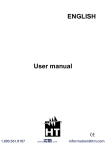
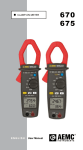
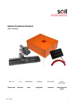
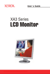
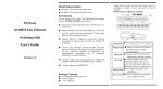
USER MANUAL For: XLCD18W TABLE OF CONTENTS CE information ------------------------------------------------------------------------ 3 Safety Precautions ------------------------------------------------------------------- 3 1. Scope -------------------------------------------------------------------------------------- 5 2. Functional specification ------------------------------------------------------------- 5 3. Controls and indicators -------------------------------------------------------------- 7 4. OSD Menu -------------------------------------------------------------------------------- 8 5. Regulatory Agency ------------------------------------------------------------------ 10 6. Reliability ----------------------------------------------------------------------------- 10 7. Mechanical ----------------------------------------------------------------------------- 11 2 CE INFORMATION The product must be installed according to the currently valid installation regulations for EMC to guarantee the designed use and to prevent EMC problems. The device supplied with this manual is according to the EC, EMC Directive, 2004/108/EC & LVD 2006/95/EC SAFETY PRECAUTIONS 1. Do not modify the three-prong grounding type monitor power plug in any way. 2. 3. 4. 5. Operate this unit only from the type of power source indicated on the label. Do not block or cover ventilation openings on the back or bottom of the monitor cabinet. Do not place this monitor near a radiator or heating vent. Do not push objects of any kind through cabinet openings. This may result in fire or electrical shock. 6. Before adding attachments always ask a service technician to perform routine safety tests to determine that equipment is in safe operating condition. Ground potential tests should be part of the routine safety check made by the service technician. 7. Do not place monitor on an unstable cart, stand, or shelf where it may fall and injure personnel or damage equipment. 8. Route power cords so that they cannot be walked upon or tripped over. Do not allow anything to rest on the power cord. 9. Do not install monitor in wet areas, or where it may be exposed to rain or water. Do not spill liquid of any kind on the unit. 10. Unplug the power cord from the unit before cleaning the display. Use only a damp cloth. Do not use alcohol, spirits, or ammonia to clean the display. DO NOT ATTEMPT TO CLEAN THE INTERIOR OF THIS UNIT- THIS ACTION MUST BE PERFORMED BY THE SERVICE TECHNICIAN AS REQUIRED DURING NORMAL MAINTENANCE. 11. Refer all servicing to qualified service personnel. REMOVAL OF BACK COVER BY UNAUTHORIZED PERSONNEL MAY EXPOSE THE USER TO DANGEROUS VOLTAGES OR OTHER HAZARDS. 12. Unplug the unit immediately and notify the service technician. A. If liquid has been spilled into the display or the display has been exposed to rain or water. B. If the unit has been dropped or the cabinet damaged. C. If fuses continue to blow. D. If the power cord is damaged or frayed. E. If a distinct change from normal operation is apparent. 3 When replacement parts are required, be sure that the service technician uses components specified by the manufacturer which have the same characteristics as the original parts. UNAUTHORIZED SUBSTITUTIONS MAY RESULT IN FIRE, ELECTRICAL SHOCK OR OTHER HAZARDS. Upon completion of any service or repairs, ask the technician to perform safety checks to determine that the equipment is in safe operating condition. WARNING: *SERIOUS SHOCK HAZARDS EXIST WITHIN THE COVERS OF THIS MONITOR. DO NOT OPEN THE COVERS UNDER ANY CIRCUMSTANCES, THERE ARE NO USER SERVICEABLE COMPONENTS INSIDE *CAUTION - USE RECOMMENDED MOUNTING APPARATUS TO AVOID RISK OF INJURY 4 1. Scope This specification is used to define the performance of the XLCD series color TFT LCD monitor. This system can support up to 1920 x 1080 VESA standard. The user friendly OSD menu is also provided to make this system easy to operate. 2 Functional Specifications 2.1 Power Supply The power supply spec is listed below, AC INPUT * AC power input range: 100 – 240 V, 50-60Hz, 1.3Arms max. * Power efficiency: ≥80% DC INPUT * DC JACK power input: 12V +/-10% 3.0A max. 2.2 PC Input VGA Input Analog RGB: 0.707 Vrms. Support VESA Standard Timing DVI Input DVI 1.0 Compatible Interface Support VESA Standard Timing 2.3 Audio Input Signal Level: 1.0 Vrms 2.4 Environmental Temperature Operating: 00C to +400C Storage: -200C to +600C Humidity Operating: 10% to 85% (non-condensing) Storage: 10% to 95% (non-condensing) 2.5 EDID This series of displays support EDID, but does not support DDC2B function. 5 2.6 Connectors A B C D A. DVI INPUT: 24 pins DVI-D Connector B. VGA INPUT: D-SUB 15 pins Connector C. AUDIO INPUT: Phone Jack, Stereo D. DC 12V INPUT: DC JACK, 5.5Ø / 2.5Ø Set up sequence 1. Make sure the power of PC and/or Video source were turned off. 2. Plug the power adapter, Video signal and VGA cable to monitor. 3. Turns the PC and/or Video source power on. 4. Plug the AC power cord onto power adapter. (Use reverse sequence to teardown the monitor) 6 3. Controls and indicators A. “i” Auto button Press the button to run the Auto Adjust Display function. B. “-“ / “+” buttons Press the buttons to scrolling the cursor to desired function. Press the buttons to adjust the value of selected function in sub OSD menu. C. “M” Menu button Press the button to show the OSD main menu. As a confirmation key during the OSD operation. D. POWER LED Indication Green - Power on Orange - Power off (Stand by) Flash Orange - Sleep mode Flash Green - Freeze status E. POWER button Press the button to turn ON or turn OFF the monitor. 7 4. OSD Menu 4.1 Menu 8 4.2 OSD Menu framework Contrast Brightness Color Color Temp USER Picture (VGA ONLY) Main Menu (VGA and DVI) Function (VGA ONLY) Exit H. Position V .Position Clock Phase Sharpness Exit Auto Adjust Color Adjust 0 ~ 100 0 ~ 100 9300 6500 5800 Red 0 ~ 255 Green 0 ~ 255 Blue 0 ~ 255 Exit 0 ~ 100 0 ~ 100 0 ~ 100 0 ~ 100 0, 1, 2, 3, 4 Yes No sRGB Exit Language OSD Menu OSD H. Position OSD V .Position OSD Timer Translucence Exit Signal Source Reset Misc. OSD Skin Volume Aspect Exit Exit 9 English, Deutsch, Francais, Italiano, , , , Pyccko 0 ~ 100 0 ~ 100 0 ~ 60 0~7 VGA DVI Yes No 0, 1, 2, 3. 4 0 ~ 100 16:9, 4:3 5. Regulatory Agency 5.1 Safety Approvals This series design shall meet the standards of the following domestic and foreign agencies: CE LVD : EN60950: 2006 + All : 2009 5.2 EMI/EMS Emission Approvals This series design shall meet following EMI/EMS specifications: FCC Compliance: FCC Rules and Regulations, Part 15, subpart B, Class A. CE COMPLIANCE: EN55022:2006 class A, EN55024:2003, EN50130-4:2003 6. Reliability Mean Time Between Failures (MTBF): MTBF shall be 30,000 hours minimum at 90% confidence level and 100% duty cycle continuous operation at 250C. The calculation shall not include LCD panel. 10 7. Mechanical 7.1 Cabinet Material: Plastic Finish: Black 7.2 Dimensions Dims: mm Model A B C D E XLCD18W 448 289 366 58 197 11