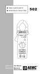
1
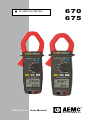
CLAMP-ON METER 670 675 ® ENGLISH User Manual INSTRUMENTS Statement of Compliance Chauvin Arnoux®, Inc. d.b.a. AEMC® Instruments certifies that this instrument has been calibrated using standards and instruments traceable to international standards. We guarantee that at the time of shipping your instrument has met its published specifications. An NIST traceable certificate may be requested at the time of purchase, or obtained by returning the instrument to our repair and calibration facility, for a nominal charge. The recommended calibration interval for this instrument is 12 months and begins on the date of receipt by the customer. For recalibration, please use our calibration services. Refer to our repair and calibration section at www.aemc.com. Serial #: _ ________________________________ Catalog #: 2117.49 / 2117.50 Model #: 670 / 675 Please fill in the appropriate date as indicated: Date Received: ____________________________ Date Calibration Due: _______________________ Chauvin Arnoux®, Inc. d.b.a AEMC® Instruments www.aemc.com Table of Contents 1. INTRODUCTION.................................... 3 1.1 International Electrical Symbols............... 4 1.2 Definition of Measurement Categories..... 4 1.3 Receiving Your Shipment......................... 5 1.4 Ordering Information................................ 5 1.4.1 Accessories/Replacement Parts... 5 2. PRODUCT FEATURES........................... 6 2.1 Description............................................... 6 2.2 Model 670/675 Control Features.............. 7 2.3 LCD Display............................................. 8 2.4 Button Functions...................................... 9 2.4.1 HOLD Button................................ 9 2.4.2 Correction of Zero in DC measurement ........................ 9 2.4.3 Auto Power OFF........................... 9 2.4.4 DISPLAY Button......................... 10 2.4.5 MIN/MAX Function (500ms)....... 10 2.4.6 Peak Function (1ms)................... 10 2.4.7 Backlight Button.......................... 10 3. SPECIFICATIONS................................ 11 3.1 Electrical Specifications......................... 11 3.2 Mechanical Specifications...................... 13 3.3 Environmental Specifications................. 14 3.4 Safety Specifications.............................. 14 4. OPERATION........................................ 15 4.1 AC Current Measurement...................... 15 4.2 AC Voltage and Current Measurement Simultaneously................ 16 4.3 4.4 4.5 4.6 4.7 4.8 4.9 4.10 DC Current Measurement (675 only).......17 AC Volt Measurement............................ 18 DC Volt Measurement............................ 19 Resistance Measurement...................... 20 Continuity Measurement........................ 21 Temperature Measurement.................... 22 Frequency Measurement Using Voltage Input.......................................... 23 Frequency Measurement Using Current Input.......................................... 24 5. MAINTENANCE................................... 25 5.1 Warning!................................................. 25 5.2 Cleaning................................................. 25 5.3 Battery Replacement.............................. 25 Repair and Calibration............................................. 27 Technical and Sales Assistance.............................. 27 Limited Warranty..................................................... 28 Warranty Repairs..................................................... 28 CHAPTER 1 INTRODUCTION Warning ● Read the user manual before operating and follow all safety information. ● Only use the meter as specified in this user manual. ● Never use this meter on a circuit with voltages greater than 600Vrms @ 50/60Hz, CAT IV or 1000V, CAT III. ● Never measure current while the test leads are connected to the input jacks. ● Do not operate the meter if the body or test leads look damaged. ● Check the rotary range switch and make sure it is at the correct position before each measurement. ● Do not perform resistance and continuity test on a live circuit. ● Use extreme caution when measuring live systems with voltages greater than 60VDC or 30VAC. ● Use extreme care when working around bus bars and bare conductors. ● Do not use the meter in over range/overload conditions ( ). ● For accurate readings, change the battery when the symbol appears. Clamp-on Meter Models 670 and 675 3 1.1 International Electrical Symbols This symbol signifies that the instrument is protected by double or reinforced insulation. This symbol on the instrument indicates a WARNING and that the operator must refer to the user manual for instructions before operating the instrument. In this manual, the symbol preceding instructions indicates that if the instructions are not followed, bodily injury, installation/sample and product damage may result. Risk of electric shock. The voltage at the parts marked with this symbol may be dangerous. This symbol refers to a type A current sensor. This symbol signifies that application around and removal from HAZARDOUS LIVE conductors is permitted. Ground. In conformity with WEEE 2002/96/EC. 1.2 Definition of Measurement Categories CAT I: For measurements on circuits not directly connected to the AC supply wall outlet such as protected secondaries, signal level, and limited energy circuits. CAT II: For measurements performed on circuits directly connected to the electrical distribution system. Examples are measurements on household appliances or portable tools. CAT III: For measurements performed in the building installation at the distribution level such as on hardwired equipment in fixed installation and circuit breakers. CAT IV: For measurements performed at the primary electrical supply (<1000V) such as on primary overcurrent protection devices, ripple control units, or meters. 4 Clamp-on Meter Models 670 and 675 1.3 Receiving Your Shipment Upon receiving your shipment, make sure that the contents are consistent with the packing list. Notify your distributor of any missing items. If the equipment appears to be damaged, file a claim immediately with the carrier and notify your distributor at once, giving a detailed description of any damage. Save the damaged packing container to substantiate your claim. 1.4 Ordering Information TRMS Clamp-on Meter Model 670.............Cat. #2117.49 Includes meter, set of test leads (red/black with safety needle tips), K-type thermocouple, one 9V battery, soft carrying case and a user manual. TRMS Clamp-on Meter Model 675.............Cat. #2117.50 Includes meter, set of test leads (red/black with safety needle tips), K-type thermocouple, one 9V battery, soft carrying case and a user manual. 1.4.1 Accessories and Replacement Parts Soft Carrying Case.......................................Cat. #2118.89 K-type Thermocouple...................................Cat. #2118.90 Color-coded Leads 5 ft w/2mm safety needle tip...............................Cat. #2140.68 Clamp-on Meter Models 670 and 675 5 CHAPTER 2 PRODUCT FEATURES 2.1 Description The AEMC® Models 670 and 675 are general purpose professional clamp-on meters that measure up to the toughest standards. These meters offer a complete set of measurement ranges (AC Amps, DC Amps [675 only], AC Volts, DC Volts, Ohms, Continuity with beeper, Frequency from V or A, and Temperature) and are in compliance with international safety and quality standards to ensure professional and reliable measuring tools. These meters are designed to measure and display amps and volts at the same time. They are also auto-ranging and provide the best measurement range and resolution for troubleshooting. The Models 670 and 675 are sized for comfortable, one-handed operation. The tapered and hooked jaw design facilitates maneuvering in crowded wiring and breaker panels, making it easy to select conductors. The jaw opening accommodates one 750 kcmil cable or two 350 kcmil cables. The large and easy-to-read 9999count LCD features comprehensive user information symbols, such as low battery, polarity, overload, and an analog bargraph for easy trend readings. Both models are equipped with a Data Hold function that freezes the measurement for later viewing, Min/Max, and Peak function for capture of signals. The Model 670 and 675 are True RMS clamp-on meters that provide RMS measurements for today’s non-linear electrical environments. 6 Clamp-on Meter Models 670 and 675 2.2 Model 670/675 Control Features 1 1 MODEL 675 TRMS CLAMP METER MODEL 670 2 TRMS CLAMP METER 2 1000V CAT III 600V CAT IV 1000V CAT III 600V CAT IV 1000A HOLD 1000A 1400A ZERO 7 3 Press 2s 7 3 8 8 4 4 DISPLAY MIN MAX PEAK DUAL TRMS DISPLAY DUAL TRMS DISPLAY 5 5 1000V CAT III 1000V CAT III 6 6 1. Jaw Assembly Model 670 - 1.65" (42mm) Model 675 - 1.58" (40mm) 2. Safety Barrier Anti-slip Guard 3. Lever for Jaw Opening/Closing 4. Button Functions (see § 2.4) 5. LCD Display 6. Positive (red) Input and COM (black) Input 7. Data Hold Button 8. Rotary Range Selector Switch Clamp-on Meter Models 670 and 675 7 2.3 LCD Display Icon Function AUTO Automatic Range HOLD Freezes the Display MIN Minimum Value MAX Maximum Value PEAK Peak Value ZERO ADC Zero Function (675 only) DC Input AC Input Auto Power OFF Indication Low Battery Continuity Beeper Enabled 8 Ω Resistance Measurement Indicator AV Current /Voltage Indicator C°/ F° Degrees Celsius/Fahrenheit Hz Frequency Measurement Indicator Clamp-on Meter Models 670 and 675 2.4 Button Functions 2.4.1 HOLD Button • The last reading may be held on the display by pressing the HOLD button. The HOLD symbol will appear when this function is activated. • To deactivate, press the HOLD button a second time. 2.4.2 Correction of Zero in DC measurement • This function on the Model 675 allows the user to zero out magnetization effects in DC current measurements. • This operation must be performed after each high amplitude current measurement. • Turn the rotary switch to ADC, with no conductor inserted into the clamp, then press the HOLD button (approximately 2 seconds) until the display shows zero current. This is also indicated by an audio beep and the symbol ZERO on the display. 2.4.3 Auto Power OFF • If there is no activity for approximately 10 minutes, the clamp will automatically shut down and the symbol will appear • To disable Auto Power OFF function, turn the rotary switch to OFF. • Press and hold down the HOLD button and set the rotary switch to any position other than OFF. • The symbol disappears and Auto Power OFF is deactivated. Clamp-on Meter Models 670 and 675 9 2.4.4 DISPLAY Button • When measuring voltage or AC current, pressing the DISPLAY button replaces the measurement shown in the lower display with the frequency measurement of the variable shown in the main display. Pressing again returns to the previous display. • In temperature measurement, pressing DISPLAY switches the displays from °C to °F of the measured temperature. 2.4.5 MIN/MAX Function (500ms) • Pressing the MIN/MAX button once will set the meter to MIN mode. • Pressing it twice will set the meter to MAX mode. • Pressing it three times will set the meter back to normal operation. 2.4.6 Peak Function (1ms) • This function is used for measuring 1-ms peak values in voltage or current. • To activate the function, press the MIN MAX PEAK button for at least 2 seconds, until PEAK is displayed. • To exit this function, press the button again for at least 2 seconds or press the HOLD button twice. The clamp will then return to normal mode. 2.4.7 Backlight Button • Press the button once to turn the backlight on. Press it again to turn it off. • When backlight is on, the meter will automatically turn the backlight off after approximately 3 minutes. 10 Clamp-on Meter Models 670 and 675 CHAPTER 3 SPECIFICATIONS The tolerances assigned to the values, or declared limits, constitute only the values guaranteed by the manufacturer. Values without a tolerance are for information only. The symbol is displayed when the input signals exceed the limit values possible in each measurement range. The symbol is displayed in °C/°F measurement when there is no input signal (open circuit). 3.1 Electrical Specifications Reference Conditions: 23°C ±3°C, 48 to 65Hz, no DC component, sinusoidal FC = 2 , 10% to 100% of range, no external alternative magnetic field, no electrical field, conductor centered in jaws (in A). AC Amperes Range Measuring Range Resolution Accuracy 1.5% ± 5cts (50 to 60Hz) 2.0% ± 5cts (50 to 500Hz) 4.5% ± 5cts (500Hz to 3kHz) 100A 0.00 to 99.99A 0.01A 1000A 100 to 1000 A 0.1A Overload: 1000Arms DC Amperes (Model 675 only) Range Measuring Range Resolution Accuracy 100A 0.00 to 99.99A 0.01A 1.2% ± 5cts 1000A 100.0 to 999.9A 0.1A 1400A 1000 to 1400A 1A 2.5% ± 5cts Overload: 1400ADC Clamp-on Meter Models 670 and 675 11 AC Volts Range Measuring Range Resolution 1000V 0.0 to 999.9V 0.1V Accuracy 1.0% ± 5cts (50 to 60Hz) 1.2% ± 5cts (50 to 500Hz) 2.5% ± 5cts (500Hz to 3kHz) Input Resistance: 1MW Overload: 1000Vrms DC Volts Range Measuring Range Resolution 1000V 0.0 to 999.9V 0.1V 1400V 1000 to 1400V 1V Accuracy 1% ± 2cts Input Resistance: 1MW Overload: 1400vDC Resistance - Ohms (Ω) Range Measuring Range Resolution 1000Ω 0.0 to 999.9Ω 0.1Ω 10,000Ω 1000 to 9999Ω 1Ω Accuracy 1% ± 3cts 3.3VDC (Vmax) Protection: 1000Vrms Continuity ( ) Range Beeper Activation Accuracy < 35Ω 1% ± 3cts 3.3VDC (Vmax) Protection: 1000Vrms Frequency (Hz) Function Range Resolution Sensitivity A - Hz 1000Hz 0.1Hz 3Arms V - Hz 10,000Hz 1Hz 5Vrms 12 Accuracy 1.0% ± 2cts Clamp-on Meter Models 670 and 675 Temperature (°C / °F) Range Measuring Range Resolution 1000°C -40 to 999.5°C 0.5°C 1200°C 1000 to 1200°C 1°C 2192°F -40 to 2192°F 1°F Accuracy 1.0% ± 2°C 1.0% ± 4°C Low Battery Indicator: is displayed when the voltage supplied by the battery is lower than the operating voltage. The measurements are then guaranteed for only a short period. Power supply: 9V, NEDA 1604 (6F22) alkaline Battery Life (no buzzer or backlight): 35 hours (670) 30 hours (675) Polarity: displayed when negative signal applied to input 3.2 Mechanical Specifications Digital Display: 3 3/4 digits LCD dual display (max reading 9999) Jaw Opening: 670: 675:1.5 Dimension (L x W x D): 670: 10.71 x 3.15 x 1.69" (272 x 80 x 43mm) 675: 10.12 x 3.15 x 1.69" (257 x 80 x 43mm) Weight: 670: 17 oz (480g) with battery 675: 15.5 oz (440g) with battery Protection Index of Housing: IP30 according to EN 60529 Ed. 92 Clamp-on Meter Models 670 and 675 13 3.3 Environmental Specifications Altitude: 2000 meters Operating Temperature: -14° to 122°F (-25 to 50°C), 80% RH, non-condensing NOTE: If the meter is to be used below 32°F (0°C), we suggest that the battery be replaced to ensure proper results. Storage Temperature: -14° to 140°F (-25° to 60°C) < 80% RH 3.4 Safety Specifications EN 61010-1 Ed.2001 EN 61010-2-032 Ed.2002 600V CAT IV, 1000V CAT III Pollution Degree 2 Electromagnetic Compatibility (per NF EN 61326) Compliant with electromagnetic compatibility standard NF EN 61326-1 (07/97) + A1 (10/98) + A2 ( 09/2001) - Radiated and conducted emission (NF EN 55022) - Radiated Immunity, criterion B (NF EN 61000-4-3) - Conducted Immunity, criterion A (NF EN 61000-4-6) - Electrostatic discharges, criterion A (NF EN 61000-4-2) - Transients, criterion B (NF EN 61000-4-4) - Shock waves, criterion A (NF EN 61000-4-5) Note: Certain high power radio-electric frequencies are, under certain conditions, capable of interfering with the metrological integrity of the meter. *Specifications are subject to change without notice 14 Clamp-on Meter Models 670 and 675 CHAPTER 4 OPERATION 4.1 AC Current Measurement NOTE: Remove the test leads before measuring current if AC voltage is not going to be measured at the same time. • Turn the rotary range switch to the range. • Press the lever to open the jaws. • Clamp the jaws around the conductor to be measured. • If reading is unstable and is hard to read, push the HOLD button and read the measurement. WARNING: If overload " " is displayed, unclamp the meter immediately . 00 A HO 10 70TER 6ME DELAMP MTROMS CL III T CA T IV V CA 00 10 600V LD DISP Y LA AL X MA N MI PEAK DU MS TR SP DI Y LA 0V 100 T III CA Clamp-on Meter Models 670 and 675 15 4.2 AC Voltage and Current Measurement Simultaneously • Turn the rotary range switch to the or range. • Connect the test probe tips to the voltage to be measured. • Press the lever to open the jaws. • Clamp the jaws around the conductor to be measured. • Voltage and current measurements will be displayed simultaneously. • If reading is unstable and is hard to read, push the HOLD button and read the measurement. WARNING: If overload " " is displayed, unclamp the meter immediately . A HO 00 10 70 R L 6METE DE AMP MTROMS CL III T CA T IV V CA 00 10 600V LD Y LA DISP AL X MA N MI PEAK DU MS TR Y LA SP DI 0V 100 T III CA 16 Clamp-on Meter Models 670 and 675 4.3 DC Current Measurement (675 only) NOTE: Remove the test leads before measuring current if DC voltage is not going to be measured at the same time • Turn the rotary range switch to the range. • If needed, the display may be “zeroed”. Press and hold down the HOLD button for approx 2s. • Clamp the jaws around the conductor to be measured. • The main display is ADC, the secondary display is VDC. The DISPLAY button is inoperative. • If reading is unstable and is hard to read, push the HOLD button and read the measurement. WARNING: If overload " " is displayed, unclamp the meter immediately . 75 L 6 ETER DE P M MOMS CLAM TR A 00 10 00A 14 T III CA IV V AT 00 C 10 0V RO 60 ZE s 2s Pres AY PL AL DU MS TR DIS V 1000T III CA Clamp-on Meter Models 670 and 675 17 4.4 AC Volt Measurement WARNING: Maximum Input Voltage is 600V. Do not exceed this voltage to avoid electrical shock and/or damage to the instrument. • Turn the rotary range switch to the range. • Insert the red test lead to the red "+" input jack and the black lead to the black "COM" input jack. • Connect the test probe tips to the voltage to be measured. • If reading is unstable and is hard to read, push the HOLD button and read the measurement. WARNING: Immediately disconnect the meter if overload " " is displayed. MODEL 670 TRMS CLAMP METER 1000V CAT III 600V CAT IV 1000A HOLD DISPLAY MIN MAX PEAK DUAL TRMS DISPLAY 1000V CAT III 18 Clamp-on Meter Models 670 and 675 4.5 DC Volt Measurement • Turn the rotary range switch to the range. • Insert the red test lead to the red "+" input jack and the black lead to the black "COM" input jack. • Connect the test probe tips to the voltage to be measured. • If reading is unstable and is hard to read, push the HOLD button and read the measurement. WARNING: Immediately disconnect the meter if overload " " is displayed. MODEL 670 TRMS CLAMP METER 1000V CAT III 600V CAT IV 1000A HOLD DISPLAY MIN MAX PEAK DUAL TRMS DISPLAY 1000V CAT III Clamp-on Meter Models 670 and 675 19 4.6 Resistance Measurement • Turn the rotary range switch to the range. • Insert the red test lead to the red "+" input jack and the black lead to the black "COM" input jack. • Bring the test probe tips into contact with the sample under test. WARNING: Immediately disconnect the meter if overload “ ” is displayed. WARNING: When making a resistance mea surement, make sure that the power is off (dead circuit), and that all capacitors in the measured circuit are fully discharged. MODEL 670 TRMS CLAMP METER 1000V CAT III 600V CAT IV 1000A HOLD DISPLAY MIN MAX PEAK DUAL TRMS DISPLAY 1000V CAT III 20 Clamp-on Meter Models 670 and 675 4.7 Continuity Measurement WARNING: When testing continuity, make sure that there is no power in the tested sample or circuit (dead circuit). This may be checked by using the voltage functions. • Turn the rotary range switch to the range. • Insert red test lead to the red "+" input jack and the black lead to the black "COM" input jack. • Bring the test probe tips into contact with the sample under test. • If the resistance is less than 40Ω, the beeper emits a continuous sound. WARNING: Immediately disconnect the meter if overload “ ” is displayed. MODEL 670 MODEL 670 TRMS CLAMP METER 1000V CAT III 600V CAT IV TRMS CLAMP METER 1000V CAT III 600V CAT IV 1000A HOLD DISPLAY MIN MAX PEAK 1000A HOLD DISPLAY MIN MAX PEAK DUAL TRMS DISPLAY DUAL TRMS DISPLAY 1000V CAT III 1000V CAT III Clamp-on Meter Models 670 and 675 21 4.8 Temperature Measurement WARNING: Make sure that there is no power in the tested sample or circuit (dead circuit). • Turn the rotary range switch to the TEMP range. • To measure the temperature, connect the K-type thermocouple probe to the input terminals, observing the polarity. • The main display is in degrees Celsius (°C) by default, and the secondary display in degrees Fahrenheit (°F). The user can change the main display to degrees Fahrenheit (°F) and the secondary display to degrees Celsius (°C) by pressing the DISPLAY button. MODEL 670 TRMS CLAMP METER 1000V CAT III 600V CAT IV 1000A HOLD DISPLAY MIN MAX PEAK DUAL TRMS DISPLAY 1000V CAT III 22 Clamp-on Meter Models 670 and 675 4.9 Frequency Measurement Using Voltage Input • Turn the rotary range switch to the press the DISPLAY button. range and • Insert red test lead to the red "+" input jack and the black lead to the black "COM" input jack. • Bring the test probe tips into contact with the sample under test. WARNING: Immediately disconnect the meter if overload “ ” is displayed. MODEL 670 TRMS CLAMP METER 1000V CAT III 600V CAT IV 1000A HOLD DISPLAY MIN MAX PEAK DUAL TRMS DISPLAY 1000V CAT III Clamp-on Meter Models 670 and 675 23 4.10 Frequency Measurement Using Current Input NOTE: Remove the test leads before measuring current if AC voltage is not going to be measured at the same time. • Turn the rotary range switch to the the DISPLAY button. range and press • Press the lever to open the jaws. • Clamp the jaws around the conductor to be measured. WARNING: If overload " " is displayed, unclamp the meter immediately . MODEL 670 TRMS CLAMP METER 1000V CAT III 600V CAT IV 1000A HOLD DISPLAY MIN MAX PEAK DUAL TRMS DISPLAY 1000V CAT III 24 Clamp-on Meter Models 670 and 675 CHAPTER 5 MAINTENANCE 5.1 Warning! • Remove the test leads on any input before opening the case. • Do not operate the clamp-on meter without a battery case cover. • To avoid electrical shock, do not attempt to perform any servicing unless you are qualified to do so. • To avoid electrical shock and/or damage to the instrument, do not get water or other foreign agents into the probe. 5.2 Cleaning • To clean the meter, wipe the case with a damp cloth and mild detergent. • Do not use abrasives or solvents. • Do not get water inside the case. This may lead to electrical shock or damage to the instrument. 5.3 Battery Replacement • The Clamp-on Meter Models 670 and 675 are powered by a 9V battery. The symbol will appear on the LCD display when the supply voltage drops below proper operating range. This indicates that the battery needs to be changed. Clamp-on Meter Models 670 and 675 25 • The meter must be in the OFF position and disconnected from any circuit or input. • Place the meter face down and remove the 2 screws with a screwdriver. • Replace the old battery with a new 9V battery, making sure of the correct positioning of the wires to prevent any pinching at closing. • Replace the battery compartment cover and tighten the screws. 26 Clamp-on Meter Models 670 and 675 Repair and Calibration To ensure that your instrument meets factory specifications, we recommend that it be submitted to our factory Service Center at one-year intervals for recalibration, or as required by other standards or internal procedures. For instrument repair and calibration: You must contact our Service Center for a Customer Service Authorization Number (CSA#). This will ensure that when your instrument arrives, it will be tracked and processed promptly. Please write the CSA# on the outside of the shipping container. If the instrument is returned for calibration, we need to know if you want a standard calibration, or a calibration traceable to N.I.S.T. (Includes calibration certificate plus recorded calibration data). Chauvin Arnoux®, Inc. d.b.a. AEMC® Instruments 15 Faraday Drive • Dover, NH 03820 USA Phone: (800) 945-2362 or (603) 749-6434 (Ext. 360) Fax: (603) 742-2346 or (603) 749-6309 [email protected] (Or contact your authorized distributor) Costs for repair, standard calibration, and calibration traceable to N.I.S.T. are available. NOTE: A CSA# must be obtained before returning any instrument. Technical and Sales Assistance If you are experiencing any technical problems, or require any assistance with the proper operation or application of your instrument, please call, mail, fax or e-mail our technical support hotline: Chauvin Arnoux®, Inc. d.b.a. AEMC® Instruments 200 Foxborough Blvd • Foxborough, MA 02035, USA Phone: (800) 343-1391 or (508) 698-2115 Fax: (508) 698-2118 [email protected] www.aemc.com NOTE: Do not ship instruments to our Foxborough, MA address. Clamp-on Meter Models 670 and 675 27 Limited Warranty The Models 670 and 675 are warranted to the owner for a period of one year from the date of original purchase against defects in manufacture. This limited warranty is given by AEMC® Instruments, not by the distributor from whom it was purchased. This warranty is void if the unit has been tampered with, abused or if the defect is related to service not performed by AEMC® Instruments. For full warranty coverage detail and registration, go to www.aemc.com What AEMC® Instruments will do: If a malfunction occurs within the one-year period, you may return the instrument to us for repair or replacement free of charge, provided we have your registration information on file or proof of purchase. AEMC® Instruments will, at its option, repair or replace the faulty material. REGISTER ONLINE AT: www.aemc.com Warranty Repairs What you must do to return an Instrument for Warranty Repair: First, request a Customer Service Authorization Number (CSA#) by phone or by fax from our Service Department (see address below), then return the instrument along with the signed CSA Form. Please write the CSA# on the outside of the shipping container. Return the instrument, postage or shipment pre-paid to: Chauvin Arnoux®, Inc. d.b.a. AEMC® Instruments Service Dept • 15 Faraday Dr • Dover, NH 03820 USA Phone: (800) 945-2362 or (603) 749-6434 (Ext. 360) Fax: (603) 742-2346 or (603) 749-6309 [email protected] Caution: To protect yourself against in-transit loss, we recommend you insure your returned material. NOTE: All customers must obtain a CSA# before returning any instrument. 28 Clamp-on Meter Models 670 and 675 ® INSTRUMENTS 05/09 99-MAN 100335 v3 Chauvin Arnoux®, Inc. d.b.a. AEMC® Instruments 15 Faraday Drive • Dover, NH 03820 USA www.aemc.com