1
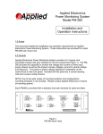
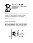
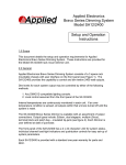
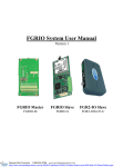
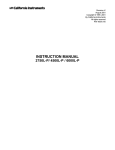
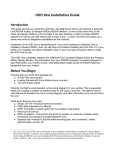
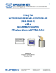
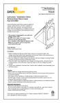
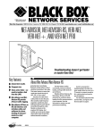
REV. A
Applied Electronics
Commercial Dimming System
UPDATE
NOTICE
This notice is to inform the end user of an additional feature added to this
DP12/2400 dimming unit. This unit has been outfitted with an RJ45 jack at the
bottom left of the unit. This jack is to facilitate connection to Applied Electronics
wall control stations with RJ45 adaptor cards. This jack allows for connections to
be made to wall stations using standard RJ45 connectors and CAT5 cabling
wired with the T-568A or B standard.
This jack is NOT to be used with Ethernet equipment such as computers
routers or hubs. It carries voltages and signals that will damage these types of
devices. Applied Electronics is NOT responsible for damage to equipment
inadvertently connected to this jack.
For questions or more information please contact Applied Electronics
Thank you,
Applied Electronics
722 Blue Crab Rd.
Newport News, VA 23606
800-883-0008
2
Applied Electronics
Commercial Dimming System
Installation and
Setup Instructions
1.0 Scope
This document details the installation and setup requirements for Applied
Electronics Commercial Dimming System. Instructions are provided for both the
Model DP 12/2400 Master Panel and the Model EP 12/2400 Expansion Panel.
Installation and setup instructions for the various Remote Wallplates Assemblies
are provided with the wallplates themselves and are not included herein.
2.0 General
Applied Electronics Commercial Dimming System consists of one DP 12/2400
Master Panel and up to seven EP 12/2400 Expansion Panels (see Figures 1 and
2). The Master Panel provides the capability to dim twelve 2400 watt outputs
internally, as well as control up to seven optional Expansion Panels. Each
Expansion Panel provides twelve additional 2400 watt outputs, for a system total
of up to 96 channels of dimming.
Dim levels for each system output may be controlled by any of the following
methods:
1. Any DMX512-compatible lighting console.
2. Any Applied Electronics Remote Wallplate Assembly.
3. Alarm inputs. Two alarm/panic switch inputs (one normally closed, one
normally open) are provided, and cause all system outputs to go to full ON
as long as the input is activated.
4. Master Panel operator controls. Eight front panel switches and an LCD
display provide local control and setup functions for all system outputs.
Internal temperatures are continuously monitored in each unit. If an over
temperature condition is sensed, all outputs within that unit are turned off until the
system is reset.
Applied Electronics • 722 Bluecrab Road • Newport News, VA 23606 • (800) 883-0008
3
DP 12/2400
COMMERCIAL DIMMER
Manual
Override
DMX
Patch
Output
Mode
Preheat
Adjust
Figure 1
DP12/2400 Master Panel
Applied Electronics • 722 Bluecrab Road • Newport News, VA 23606 • (800) 883-0008
4
EP 12/2400
COMMERCIAL DIMMER UNIT
POWER
OVER TEMP.
Figure 2
EP12/2400 Expansion Panel
Applied Electronics • 722 Bluecrab Road • Newport News, VA 23606 • (800) 883-0008
5
3.0 Specifications
- Input Voltage: 110VAC / 208VAC 3-Phase or 110VAC / 240VAC Single
Phase
- Input Current: 120A x 2 (for single phase sources) or 80A x 3 (for 3phase sources)
- Dimming Outputs: 12 channels 120VAC 20A @ 2400W
- Weight: 56 lbs.
- Outside Dimensions: 23.5“high x 17“wide x 7“deep
- Operational Ambient Temperature: 32o to 104o F (0o to 40o C)
3.1 Specifications (EURO)
- Input Voltage: 220VAC / 440VAC 3-Phase or 220VAC / 440VAC Single
Phase
- Dimming Outputs: 12 channels 220VAC 20A 2400W
4.0 Chassis Mounting
Each dimmer panel should be mounted to a wall or other fixed structure. Note
that all dimmers are inherently noisy devices, and care should be taken not to
mount the panels in a location where audible noise could be a distraction.
Clearances between each unit and adjacent structures should meet the following
guidelines:
Left and Right Side: 8” minimum clearance*
Bottom: 12” minimum clearance
Top: 24” minimum clearance
*Allow 12” minimum clearance between units if mounting two or more
units side-by-side
Four mounting holes are provided in the rear of each panel. To access these
holes, loosen the four captive thumbscrews provided on the front of the unit.
Mounting details are provided in Figure 3.
5.0 System Wiring Details
The following sections detail control and power wiring requirements for the
DP12/2400 Commercial Dimmer and the EP12/2400 Expansion Panel. Refer to
Figure 4 for Terminal Block and Ground/Neutral bar locations.
5.1 DP12/2400 Control I/O Connections
Applied Electronics • 722 Bluecrab Road • Newport News, VA 23606 • (800) 883-0008
6
Various system controls input and output connections should be made in
accordance with Figure 5 and as detailed below. Note that knockouts are
provided in the upper left corner of the DP12/2400 chassis for this purpose.
RECOMENDED
BOLT SIZE: 1/4”
20-3/4”
14-1/2”
Figure 3
Chassis Mounting Details
Applied Electronics • 722 Bluecrab Road • Newport News, VA 23606 • (800) 883-0008
7
Figure 4
Terminal Block Locations
Applied Electronics • 722 Bluecrab Road • Newport News, VA 23606 • (800) 883-0008
8
DMX
INPUT
EXPANSION PANEL
OUTPUT
WALLPLATE INTERFACE
TREM BLOCK or RJ45
GND
B
A
GND
B
A
GND
B
A
+18V
SHIELD
N/C 1
ALARM N/C 2
INPUTS N/O 1
N/O 2
TB1
1
2
3
4
5
6
7
8
9
10
11
12
13
14
15
Figure 5
DP12/2400 Control I/O Connections
WARNING
VERIFY THAT NO INPUT POWER IS BEING PROVIDED TO
THE CHASSIS PRIOR TO MAKING THE FOLLOWING
CONNECTIONS.
DMX Input – Connect any DMX512-compatible lighting console to the sidemounted 5-pin XLR connector using a standard DMX cable, or to positions 1-3 of
Terminal Block TB1 as shown. If no DMX512 console is to be used with the
system, these terminals should be left unconnected.
Expansion Chassis Output – Connect TB1 positions 4-6 to the EP 12/2400
Expansion Panel TB1 positions 1-3 (if applicable). If more than one Expansion
Panel is provided, connect all EP12/2400 TB1 positions 1-3 together (see section
5.2). If no Expansion Panels are provided with the system, these terminals
should be left unconnected.
Wallplate Interface – If the system is provided with remote control
wallplate assemblies, positions 7-11 of TB1 should be connected to the
wallplates as indicated. Note that wiring to the wallplates should be 4 conductor
(2 twisted pairs) with shield. Connect one twisted pair to terminals 7 and 10
(GND and +18V) and the other pair to terminals 8 and 8 (B and A). If no wall
plates were provided with the system, these terminals should be left
unconnected. Wall plates can also be connected through the RJ45 connector
Applied Electronics • 722 Bluecrab Road • Newport News, VA 23606 • (800) 883-0008
9
located at the top of the unit using CAT5 cable (or better) and standard RJ45
connectors in either T-568A or T-568B configuration. If not familiar with these
connections please seek the assistance from an electrician or IT professional.
NOTE: This jack is NOT to be used with Ethernet equipment such as
computers routers or hubs. It carries voltages and signals that will damage these
types of devices. Applied Electronics is NOT responsible for damage to
equipment inadvertently connected to this jack.
Alarm Input (N/C) – A normally closed alarm/panic switch may be connected to
TB1 positions 12-13. Breaking the connection between these two terminals will
cause all system outputs to go full ON. Note that the system is shipped with a
jumper connecting these two positions. If this feature is used, remove this
jumper and wire to the terminals as indicated. If this feature is not required, the
factory-installed jumper should be left in place.
Alarm Input (N/O) – If applicable, a normally open alarm/panic switch may be
connected to TB1 positions 14-15. If this feature is not required, these terminals
should be left unconnected.
5.2 EP12/2400 Control I/O Connections
For systems provided with one or more EP12/2400 Expansion Panels, control
input connections from the DP12/2400 Master Panel should be made in
accordance with Figure 6 and as detailed below. Note that knockouts are
provided in the upper left corner of the EP12/2400 chassis for this purpose.
WARNING
VERIFY THAT NO INPUT POWER IS BEING PROVIDED TO
THE CHASSIS PRIOR TO MAKING THE FOLLOWING
CONNECTIONS.
Master Panel Input – Connect DP12/2400 TB1 positions 4-6 to the EP 12/2400
Expansion Panel TB1 positions 1-3. If more than one Expansion Panel is
provided, connect all EP12/2400 TB1 positions 1-3 together as shown
TB1
4
GND
MASTER
PANEL
B
5
`OUTPUT
A
6
TB1
1
2
3
FIRST
EXPANSION
PANEL
5.3 Power Output Connections (DP12/2400 and EP12/2400)
TOGND
OTHER
EXPANSION
B
PANELS
A
Figure 6
EP12/2400 Control I/O Connections
Applied Electronics • 722 Bluecrab Road • Newport News, VA 23606 • (800) 883-0008
10
System power output connections should be made in accordance with Figure 7
and as detailed below. Note that knockouts are provided in the upper right
corner of the DP12/2400 and EP12/2400 chassis for this purpose.
WARNING
VERIFY THAT NO INPUT POWER IS BEING PROVIDED TO
THE CHASSIS PRIOR TO MAKING THE FOLLOWING
CONNECTIONS.
Neutral
Bar
Hot Connections
Ground
Bar
1
2
3
4
5
6
7
8
9
10 11 12
TB2
Neutral Connections
Ground Connections
Figure 7
Power Output Connections
Ground Connections – 14AWG - 10AWG Copper conductors only. Connections
torque 10in/lbs. Earth ground wires for each output channel may be connected
to the system Ground bar. Note that it is permissible to bypass this feature if
Ground wires are routed directly to the lighting fixtures being controlled.
Neutral Connections – 14AWG - 10AWG Copper conductors only. Connections
torque 10in/lbs. Neutral wires for each output channel may be connected to the
system Neutral bar. Note that it is permissible to bypass this feature if Neutral
wires are routed directly to the lighting fixtures being controlled.
Hot Connections – 14AWG - 10AWG Copper conductors only. Connections
torque 10in/lbs. Hot wires for each output channel should be connected to the
corresponding position on TB2. Position 1, on the far left of TB2, is the Channel
1 output terminal. The outputs proceed sequentially through Channel 12 on the
far right of TB2. Note that the system is capable of raising and lowering the
levels of several channels together using a single control channel (see System
Setup instructions below). If this capability is to be utilized, channels to be
grouped together should be wired to adjacent outputs. If one or more EP12/2400
Applied Electronics • 722 Bluecrab Road • Newport News, VA 23606 • (800) 883-0008
11
Expansion Panels are provided with the system, it is permissible to group
channels across the boundary between two or more chassis. For instance, if four
2400 Watt output channels are required for a specific group of lights that are to
be raised/lowered together, then these fixtures may be wired to Channels 1-4, or
Channels 3-6, or Channels 11-12 in the DP12/2400 and Channels 1-2 in the first
EP12/2400.
More than one lighting fixture may be connected to each output channel, as long
as each channel’s load does not exceed 2400 watts.
5.4 Power Input Connections (DP12/2400 and EP12/2400)
The DP12/2400 Commercial Dimmer system may be configured for use with 3phase or single-phase power sources. In 3-phase mode, blue wires marked with
“Black” and “Red” tape should be connected to the right side of TB3 position 5
(bottom). In single-phase configuration, black taped wire is connected to TB3
position 3 and red taped wire is connected to TB3 position 4. The resulting
phase/channel assignments for each configuration is as follows:
Configuration
3-Phase
Single Phase
1
A
A
2
A
A
3
B
B
Channel Phase Assignment
4
5
6
7
8
9
B
C
C
A
A
B
B
B
B
A
A
B
10
B
B
11
C
A
12
C
A
System power input connections should be made in accordance with Figure 8
and as detailed below. Note that knockouts are provided in the bottom left corner
of the DP12/2400 and EP12/2400 chassis for this purpose.
Ground
Neutral
Phase A
Figure 8
Power Input Connections
6AWG - 1AWG
Copper conductors only
Torque 18 in/lbs.
TB3
Phase B
Phase C
Applied Electronics • 722 Bluecrab Road • Newport News, VA 23606 • (800) 883-0008
12
WARNING
BE SURE THAT POWER TO THE INPUT POWER WIRING IS
OFF BEFORE CONNECTION IS MADE TO THE POWER
INPUT TERMINALS.
Ground Connection – Earth ground input should be connected to TB3 position 1
(top).
Neutral Connection – Power Neutral input should be connected to TB3 position
2.
Phase A Connection – Connect one phase of system power (hot) to TB3 position
3.
Phase B Connection – Connect a second phase of system power (hot) to TB3
position 4.
Phase C Connection – In 3-phase power systems, connect the third phase of
system power (hot) to TB3 position 5 (bottom).
6.0 System Setup
After all system control and power wiring are connected as detailed in section 5
above, turn all 12 output channel circuit breakers OFF, turn the DMX512 lighting
console OFF, set all remote wallplate levels to “0”, and energize the system.
The system front panel LCD display should display the following message for a
few seconds:
APPLIED ELECTRONICS
DP 12/2400 COMMERCIAL DIMMER
Manual
Override
DMX
Patch
Output
Mode
Preheat
Adjust
After initialization, the LCD will display the following system status screen:
Applied Electronics • 722 Bluecrab Road • Newport News, VA 23606 • (800) 883-0008
13
PHZ A:OK PHZ B:OK PHZ C:OK
Temp:NORM
Valid DMX Input: NO
Base Address:
1
Manual
Override
DMX
Patch
Output
Mode
Preheat
Adjust
Note: If the system is powered by a single phase (220/240 VAC) source, the LCD
will not display the “PHZ C: OK” message.
If the system is provided with one or more EP12/2400 Expansion Panels, the
“POWER” LED should light on each panel.
With all sliders set to “0” or “OFF”, turn on the DMX512 lighting console. The
status message should change to “Valid DMX Input: YES”.
6.1 Manual Override
The Manual Override function allows maintenance personnel to override all DMX,
Alarm, and wallplate inputs and adjust each output individually. Turn ON the
front panel circuit breaker for Output Channel 1 (the leftmost breaker). The
fixture connected to Output 1 should remain OFF. Press the front panel Manual
Override button. The Manual Override LED should light, and the LCD will display
the following:
Out: 01 02 03 04 05 06 07 08 09 10 11 12
Lvl: 00 00 00 00 00 00 00 00 00 00 00 00
Manual
Override
DMX
Patch
Output
Mode
Preheat
Adjust
The top row of numbers in the LCD display indicates channel output numbers.
The bottom row indicates the current level of each output. A flashing cursor
(shown in the figure with a gray background) indicates the current output
Applied Electronics • 722 Bluecrab Road • Newport News, VA 23606 • (800) 883-0008
14
channel. Press the UP and DOWN buttons to the left of the Manual Override
switch to change the value of Output 1 from 0% to 100%. (Note: 100% level is
displayed as “FL” for “Full” on the LCD display.) Verify that the lighting fixture(s)
connected to Output 1 light and dim accordingly. To adjust another output
channel, turn on the corresponding front panel circuit breaker, press the LEFT
and RIGHT buttons to the left of the Manual Override switch to select the desired
channel, then use the UP and DOWN buttons as above to adjust the output level.
Repeat these steps until all output channels have been verified. Note that in
systems with one or more EP12/2400 Expansion Panels, moving the cursor offscreen to the right or left causes the next (or previous) 12 channel levels to be
displayed.
Pressing the Manual Override switch again causes the associated LED to
extinguish and the LCD to revert to the system status screen.
Note that when the system is in normal usage, pressing the Manual Override
button causes all outputs to freeze at their current levels (as set externally by the
DMX console or remote wallplates) until the channels are adjusted manually, or
until the Manual Override switch is pressed again. When the system exits
Manual Override mode, control is immediately returned to the external (DMX/
wallplate/Alarm) devices.
6.2 DMX Patch
The DP12/2400 DMX Patch function allows maintenance personnel to adjust the
base DMX address for the system. Adjusting this parameter is generally not
necessary if the DP12/2400 system is the only dimmer connected to the DMX512
console output.
To adjust the DMX base address, press the DMX Patch switch on the system
front panel. The DMX Patch LED lights and the following is displayed on the
LCD screen:
Applied Electronics • 722 Bluecrab Road • Newport News, VA 23606 • (800) 883-0008
DMX Base Address:
Manual
Override
1
15
DMX
Patch
Output
Mode
Preheat
Adjust
Press UP and DOWN arrows to adjust the system DMX base address to the
desired value. Press the DMX Patch again to return to the system status display.
Note that the system does not respond to external (DMX/Wallplate/Alarm) control
signals while in DMX Patch mode. DMX Patch values are stored in non-volatile
memory and are not lost in the case of a power outage.
6.3 Output Mode
The DP12/2400 Output Mode performs two important functions: (1) Channels
may be set to operate in non-dimming mode (also called “switch” or “relay”
mode), and (2) Channels may be grouped together so that changing the level on
one channel changes the level on all channels equally.
Press the Output Mode switch on the DP12/2400 front panel. The Output Mode
LED should light, and the LCD will display the following:
Out: 01 02 03 04 05 06 07 08 09 10 11 12
D/S: D D D D D D D D D D D D
Manual
Override
DMX
Patch
Output
Mode
Preheat
Adjust
The “D” under each output channel indicates that associated channel is set to
“Dim” mode. This is the default operating mode for each channel. Pressing the
UP button once changes the selected channel’s output mode to “S”, indicating
“switch” mode. When an output channel is in Switch mode, the output level of
that channel changes from OFF when the input control signal is at 50% or less,
Applied Electronics • 722 Bluecrab Road • Newport News, VA 23606 • (800) 883-0008
16
to full ON when the input level is set to greater than 50%. This feature allows
non-dimmable (on/off) devices to be controlled by the dimming system.
Pressing the UP button again changes the selected channel’s output mode to “<”,
indicating that that channel’s level will track the level of the preceding channel.
This feature is useful when it is preferable to use one channel level to control
several outputs simultaneously, particularly in cases where a group of lights
should always be at the same level but (because of their power consumption)
must be assigned to several separate outputs. It also permits a single slider on a
remote wallplate controller to raise and lower the brightness of a group of lights.
Consider the following sample display:
Out: 01 02 03 04 05 06 07 08 09 10 11 12
D/S: D < < < D D < < D D S <
Manual
Override
DMX
Patch
Output
Mode
Preheat
Adjust
When set up as shown, Output Channels 1 through 4 will dim as determined by
the input level for Channel 1, Channels 6 through 8 will dim as determined by the
input level for Channel 6, and Channels 11 and 12 will switch ON and OFF as
determined by the input level for Channel 11. Channels 5, 9, and 10 will operate
independently of all other channels.
Note that in systems with one or more EP12/2400 Expansion Panels, moving the
cursor off-screen to the right or left causes the next (or previous) screen of 12
output modes to be displayed.
It is permissible to group channels across the boundary between screens. That
is, channels 13 and 14 (for instance) can be programmed to track channel 12 on
the previous screen.
Pressing Output Mode again causes the Output Mode LED to extinguish and the
system status screen to be displayed. Output Mode settings are saved in nonvolatile memory and are not lost in the case of a power outage.
6.3 Preheat Adjust
Applied Electronics • 722 Bluecrab Road • Newport News, VA 23606 • (800) 883-0008
17
The DP12/2400 Preheat Adjust function allows maintenance personnel set to a
minimum value for the output level of individual channels. This feature has two
benefits: (1) Bulb life is extended for fixtures that are frequently taken from full
OFF to full ON repeatedly, and (2) Bulbs reach full brightness more quickly when
they begin with a small trickle current running through them. These benefits are
most noticeable in fixtures that are used in “Chase” mode (see DMX lighting
console instructions).
To set preheat values, press Preheat Adjust on the system front panel. The
Preheat Adjust LED should light, and the LCD will display the following:
Out: 01 02 03 04 05 06 07 08 09 10 11 12
Pre: 00 00 00 00 00 00 00 00 00 00 00 00
Manual
Override
DMX
Patch
Output
Mode
Preheat
Adjust
As in the other adjustment modes, the UP and DOWN buttons are used to set
the desired Preheat level, and the RIGHT and LEFT buttons to select the
channel to be adjusted. Note that Preheat levels for each channel may be set
from 0% to 12% of maximum brightness. Preheat levels for grouped output
channels all track the primary (lowest) channel’s value; preheat levels for the
tracking channels are ignored. Preheat values for outputs set to “Switch”
(ON/OFF) mode are also ignored.
Pressing Preheat Adjust again causes the Preheat Adjust LED to extinguish and
the system status screen to be displayed. Preheat Adjust settings are saved in
non-volatile memory and are not lost in the case of a power outage.
7.0 Maintenance Issues
When properly mounted and wired as specified herein, the DP12/2400
Commercial Dimmer system should provide years of trouble-free service.
However, certain failure conditions may cause the unit to malfunction or cease
operation completely. This section provides an overview of the most common
failure conditions.
Applied Electronics • 722 Bluecrab Road • Newport News, VA 23606 • (800) 883-0008
18
7.1 Excessive System Current
Each DP12/2400 and EP12/2400 output channel is rated at 2400 watts, or 20
amps at 120 VAC. The total current rating of each panel is 80 amps per phase
for a 3-phase system, and 120 amps per leg for a single phase system. While
each channel’s output current is supplied through a circuit breaker which limits
that channels’ current to 20 amps, there is no internal master circuit breaker to
ensure that the system’s total current draw is within the specified limits. Before
operating the system, be sure that power input lines are externally protected from
an over current condition.
7.2 Thermal Overload
Each DP12/2400 Master Panel and EP12/2400 Expansion Panel is supplied with
thermal monitoring circuitry which continually monitors the unit’s internal
temperature. If air pathways into or out of the chassis are blocked, if the unit’s
side-mounted heat sinks are covered, or if the unit is mounted too close to
nearby walls or heat sources (such as other dimmer panels), it is possible for the
dimmer system to overheat. When an over temperature condition is sensed in
the DP12/2400 Master Panel, the LCD displays the following message:
OVER TEMPERATURE DETECTED
TURN POWER OFF TO RESET
Manual
Override
DMX
Patch
Output
Mode
Preheat
Adjust
When an over temperature condition is sensed in the EP12/2400 Expansion
Panel, the red front panel OVER TEMP LED is lit.
Note that if an Expansion Panel senses an over temperature condition, all 12
internal channels turn OFF until the system is reset (by cycling the power), but
the rest of the dimmer system will still function properly. However, if the Master
Panel senses an over temperature condition, all 12 internal outputs are turned
OFF and any connected Expansion Panels will lock all outputs at their current
levels until the system power is cycled OFF and ON.
Applied Electronics • 722 Bluecrab Road • Newport News, VA 23606 • (800) 883-0008
19
7.3 Control Board Fuses
Improperly wired control I/O lines can cause the dimmer’s control electronics to
draw excessive current. To protect against this, three fuses are provided on
each unit’s circuit breaker panel. To access the fuses, open the hinged door on
the DP12/2400 or EP12/2400 chassis. All fuses are rated ½ Amp.
Applied Electronics • 722 Bluecrab Road • Newport News, VA 23606 • (800) 883-0008