1
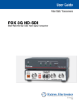
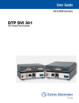
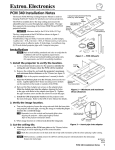
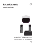
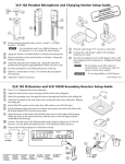
PVT CV D, PVT RGB D, PVT RGB D Plus
PVT CV AAP, and PVT RGB AAP
PoleVault® Twisted Pair Input Wallplates
(Decora® and AAP Models)
68-1259-01
Rev. C
09 09
Precautions
Safety Instructions • English
This symbol is intended to alert the user of important operating and maintenance
(servicing) instructions in the literature provided with the equipment.
This symbol is intended to alert the user of the presence of uninsulated dangerous
voltage within the product’s enclosure that may present a risk of electric shock.
Caution
Read Instructions • Read and understand all safety and operating instructions before using the equipment.
Retain Instructions • The safety instructions should be kept for future reference.
Follow Warnings • Follow all warnings and instructions marked on the equipment or in the user
information.
Avoid Attachments • Do not use tools or attachments that are not recommended by the equipment
manufacturer because they may be hazardous.
Consignes de Sécurité • Français
Ce symbole sert à avertir l’utilisateur que la documentation fournie avec le matériel
contient des instructions importantes concernant l’exploitation et la maintenance
(réparation).
Ce symbole sert à avertir l’utilisateur de la présence dans le boîtier de l’appareil
de  tensions dangereuses non isolées posant des risques d’électrocution.
Attention
Lire les instructions• Prendre connaissance de toutes les consignes de sécurité et d’exploitation avant
d’utiliser le matériel.
Conserver les instructions• Ranger les consignes de sécurité afin de pouvoir les consulter à l’avenir.
Respecter les avertissements • Observer tous les avertissements et consignes marqués sur le matériel ou
présentés dans la documentation utilisateur.
Eviter les pièces de fixation • Ne pas utiliser de pièces de fixation ni d’outils non recommandés par le
fabricant du matériel car cela risquerait de poser certains dangers.
Warning
Power sources • This equipment should be operated only from the power source indicated on the product. This
equipment is intended to be used with a main power system with a grounded (neutral) conductor. The
third (grounding) pin is a safety feature, do not attempt to bypass or disable it.
Power disconnection • To remove power from the equipment safely, remove all power cords from the rear of
the equipment, or the desktop power module (if detachable), or from the power source receptacle (wall
plug).
Power cord protection • Power cords should be routed so that they are not likely to be stepped on or pinched by
items placed upon or against them.
Servicing • Refer all servicing to qualified service personnel. There are no user-serviceable parts inside. To
prevent the risk of shock, do not attempt to service this equipment yourself because opening or removing
covers may expose you to dangerous voltage or other hazards.
Slots and openings • If the equipment has slots or holes in the enclosure, these are provided to prevent
overheating of sensitive components inside. These openings must never be blocked by other objects.
Lithium battery • There is a danger of explosion if battery is incorrectly replaced. Replace it only with the
same or equivalent type recommended by the manufacturer. Dispose of used batteries according to the
manufacturer’s instructions.
Avertissement
Alimentations• Ne faire fonctionner ce matériel qu’avec la source d’alimentation indiquée sur l’appareil. Ce
matériel doit être utilisé avec une alimentation principale comportant un fil de terre (neutre). Le troisième
contact (de mise à la terre) constitue un dispositif de sécurité : n’essayez pas de la contourner ni de la
désactiver.
Déconnexion de l’alimentation• Pour mettre le matériel hors tension sans danger, déconnectez tous les cordons
d’alimentation de l’arrière de l’appareil ou du module d’alimentation de bureau (s’il est amovible) ou encore
de la prise secteur.
Protection du cordon d’alimentation • Acheminer les cordons d’alimentation de manière à ce que personne ne
risque de marcher dessus et à ce qu’ils ne soient pas écrasés ou pincés par des objets.
Réparation-maintenance • Faire exécuter toutes les interventions de réparation-maintenance par un technicien
qualifié. Aucun des éléments internes ne peut être réparé par l’utilisateur. Afin d’éviter tout danger
d’électrocution, l’utilisateur ne doit pas essayer de procéder lui-même à ces opérations car l’ouverture ou le
retrait des couvercles risquent de l’exposer à de hautes tensions et autres dangers.
Fentes et orifices • Si le boîtier de l’appareil comporte des fentes ou des orifices, ceux-ci servent à empêcher
les composants internes sensibles de surchauffer. Ces ouvertures ne doivent jamais être bloquées par des
objets.
Lithium Batterie • Il a danger d’explosion s’ll y a remplacment incorrect de la batterie. Remplacer uniquement
avec une batterie du meme type ou d’un ype equivalent recommande par le constructeur. Mettre au reut les
batteries usagees conformement aux instructions du fabricant.
Sicherheitsanleitungen • Deutsch
Stromquellen • Dieses Gerät sollte nur über die auf dem Produkt angegebene Stromquelle betrieben werden.
Dieses Gerät wurde für eine Verwendung mit einer Hauptstromleitung mit einem geerdeten (neutralen)
Leiter konzipiert. Der dritte Kontakt ist für einen Erdanschluß, und stellt eine Sicherheitsfunktion dar. Diese
sollte nicht umgangen oder außer Betrieb gesetzt werden.
Dieses Symbol soll den Benutzer darauf aufmerksam machen, daß im Inneren des
Gehäuses dieses Produktes gefährliche Spannungen, die nicht isoliert sind und
die einen elektrischen Schock verursachen können, herrschen.
Stromunterbrechung • Um das Gerät auf sichere Weise vom Netz zu trennen, sollten Sie alle Netzkabel
aus der Rückseite des Gerätes, aus der externen Stomversorgung (falls dies möglich ist) oder aus der
Wandsteckdose ziehen.
Achtung
Lesen der Anleitungen • Bevor Sie das Gerät zum ersten Mal verwenden, sollten Sie alle Sicherheits-und
Bedienungsanleitungen genau durchlesen und verstehen.
Aufbewahren der Anleitungen • Die Hinweise zur elektrischen Sicherheit des Produktes sollten Sie
aufbewahren, damit Sie im Bedarfsfall darauf zurückgreifen können.
Befolgen der Warnhinweise • Befolgen Sie alle Warnhinweise und Anleitungen auf dem Gerät oder in der
Benutzerdokumentation.
Keine Zusatzgeräte • Verwenden Sie keine Werkzeuge oder Zusatzgeräte, die nicht ausdrücklich vom
Hersteller empfohlen wurden, da diese eine Gefahrenquelle darstellen können.
Instrucciones de seguridad • Español
Schutz des Netzkabels • Netzkabel sollten stets so verlegt werden, daß sie nicht im Weg liegen und niemand
darauf treten kann oder Objekte darauf- oder unmittelbar dagegengestellt werden können.
Wartung • Alle Wartungsmaßnahmen sollten nur von qualifiziertem Servicepersonal durchgeführt werden.
Die internen Komponenten des Gerätes sind wartungsfrei. Zur Vermeidung eines elektrischen Schocks
versuchen Sie in keinem Fall, dieses Gerät selbst öffnen, da beim Entfernen der Abdeckungen die Gefahr
eines elektrischen Schlags und/oder andere Gefahren bestehen.
Schlitze und Öffnungen • Wenn das Gerät Schlitze oder Löcher im Gehäuse aufweist, dienen diese zur
Vermeidung einer Überhitzung der empfindlichen Teile im Inneren. Diese Öffnungen dürfen niemals von
anderen Objekten blockiert werden.
Litium-Batterie • Explosionsgefahr, falls die Batterie nicht richtig ersetzt wird. Ersetzen Sie verbrauchte
Batterien nur durch den gleichen oder einen vergleichbaren Batterietyp, der auch vom Hersteller empfohlen
wird. Entsorgen Sie verbrauchte Batterien bitte gemäß den Herstelleranweisungen.
Advertencia
Este símbolo se utiliza para advertir al usuario sobre instrucciones importantes
de operación y mantenimiento (o cambio de partes) que se desean destacar en el
contenido de la documentación suministrada con los equipos.
Alimentación eléctrica • Este equipo debe conectarse únicamente a la fuente/tipo de alimentación eléctrica
indicada en el mismo. La alimentación eléctrica de este equipo debe provenir de un sistema de distribución
general con conductor neutro a tierra. La tercera pata (puesta a tierra) es una medida de seguridad, no
puentearia ni eliminaria.
Este símbolo se utiliza para advertir al usuario sobre la presencia de elementos con
voltaje peligroso sin protección aislante, que puedan encontrarse dentro de la caja
o alojamiento del producto, y que puedan representar riesgo de electrocución.
Desconexión de alimentación eléctrica • Para desconectar con seguridad la acometida de alimentación eléctrica
al equipo, desenchufar todos los cables de alimentación en el panel trasero del equipo, o desenchufar el
módulo de alimentación (si fuera independiente), o desenchufar el cable del receptáculo de la pared.
Precaucion
Leer las instrucciones • Leer y analizar todas las instrucciones de operación y seguridad, antes de usar el
equipo.
Conservar las instrucciones • Conservar las instrucciones de seguridad para futura consulta.
Obedecer las advertencias • Todas las advertencias e instrucciones marcadas en el equipo o en la
documentación del usuario, deben ser obedecidas.
Evitar el uso de accesorios • No usar herramientas o accesorios que no sean especificamente recomendados
por el fabricante, ya que podrian implicar riesgos.
安全须知 • 中文
这个符号提示用户该设备用户手册中有重要的操作和维护说明。
这个符号警告用户该设备机壳内有暴露的危险电压,有触电危险。
注意
Vorsicht
Dieses Symbol soll dem Benutzer in der im Lieferumfang enthaltenen
Dokumentation besonders wichtige Hinweise zur Bedienung und Wartung
(Instandhaltung) geben.
阅读说明书 • 用户使用该设备前必须阅读并理解所有安全和使用说明。
保存说明书 • 用户应保存安全说明书以备将来使用。
遵守警告 • 用户应遵守产品和用户指南上的所有安全和操作说明。
避免追加 • 不要使用该产品厂商没有推荐的工具或追加设备,以避免危险。
Protección del cables de alimentación • Los cables de alimentación eléctrica se deben instalar en lugares donde
no sean pisados ni apretados por objetos que se puedan apoyar sobre ellos.
Reparaciones/mantenimiento • Solicitar siempre los servicios técnicos de personal calificado. En el interior no
hay partes a las que el usuario deba acceder. Para evitar riesgo de electrocución, no intentar personalmente
la reparación/mantenimiento de este equipo, ya que al abrir o extraer las tapas puede quedar expuesto a
voltajes peligrosos u otros riesgos.
Ranuras y aberturas • Si el equipo posee ranuras o orificios en su caja/alojamiento, es para evitar el
sobrecalientamiento de componentes internos sensibles. Estas aberturas nunca se deben obstruir con otros
objetos.
Batería de litio • Existe riesgo de explosión si esta batería se coloca en la posición incorrecta. Cambiar esta
batería únicamente con el mismo tipo (o su equivalente) recomendado por el fabricante. Desachar las
baterías usadas siguiendo las instrucciones del fabricante.
警告
电源 • 该设备只能使用产品上标明的电源。 设备必须使用有地线的供电系统供电。 第三条线
(地线)是安全设施,不能不用或跳过 。
拔掉电源 • 为安全地从设备拔掉电源,请拔掉所有设备后或桌面电源的电源线,或任何接到市
电系统的电源线。
电源线保护 • 妥善布线, 避免被踩踏,或重物挤压。
维护 • 所有维修必须由认证的维修人员进行。 设备内部没有用户可以更换的零件。为避免出现
触电危险不要自己试图打开设备盖子维修该设备。
通风孔 • 有些设备机壳上有通风槽或孔,它们是用来防止机内敏感元件过热。 不要用任何东
西挡住通风孔。
锂电池 • 不正确的更换电池会有爆炸的危险。必须使用与厂家推荐的相同或相近型号的电池。
按照生产厂的建议处理废弃电池。
声明
所使用电源为 A 级产品,在生活环境中,该产品可能会造成无线电干扰。在这种情况下,可能需要用户对其干扰采取切实可行的措施。
FCC Class A Notice
This equipment has been tested and found to comply with the limits for a Class A digital device, pursuant to part 15 of the FCC Rules. Operation is subject to
the following two conditions: (1) this device may not cause harmful interference, and (2) this device must accept any interference received, including interference
that may cause undesired operation. The Class A limits are designed to provide reasonable protection against harmful interference when the equipment is
operated in a commercial environment. This equipment generates, uses, and can radiate radio frequency energy and, if not installed and used in accordance with
the instruction manual, may cause harmful interference to radio communications. Operation of this equipment in a residential area is likely to cause harmful
interference, in which case the user will be required to correct the interference at his own expense.
N
This unit was tested with shielded cables on the peripheral devices. Shielded cables must be used with the unit to ensure compliance with FCC emissions limits.
For more information on safety guidelines, regulatory compliances,
EMI/EMF compliance, accessibility, and related topics, click here.
Table of Contents
Chapter One • Introduction . ..................................................................................................... 1-1
About the PVT Input Wallplates. ....................................................................................... 1-2
Transmission distance................................................................................................................ 1-2
About the PVT CV D................................................................................................................... 1-3
About the PVT CV AAP............................................................................................................. 1-3
About the PVT RGB D................................................................................................................ 1-4
About the PVT RGB D Plus..................................................................................................... 1-4
About the PVT RGB AAP.......................................................................................................... 1-4
Application Diagram. ............................................................................................................... 1-5
Chapter Two • Installation ......................................................................................................... 2-1
Important safety instructions................................................................................................... 2-2
Installing the PVT CV and PVT RGB Decora Models............................................... 2-3
To install into a mud ring......................................................................................................... 2-3
To install into a new wall box.................................................................................................. 2-4
Final installation. ....................................................................................................................... 2-5
Installing the PVT CV and PVT RGB AAP Models..................................................... 2-6
Connections and Settings...................................................................................................... 2-7
Front panel features and cabling............................................................................................ 2-7
Rear panel — output cabling................................................................................................... 2-8
Rear panel — features ............................................................................................................. 2-8
Appendix A • Reference Material......................................................................................... A-1
Specifications............................................................................................................................... A-2
Part Numbers................................................................................................................................. 2-5
Included Parts............................................................................................................................. 2-5
Optional Accessories. ............................................................................................................... 2-5
Cables. ......................................................................................................................................... 2-5
AAP accessories ......................................................................................................................... 2-5
Template Dimensions............................................................................................................... 2-6
All trademarks mentioned in this manual are the properties of their respective owners.
PVT Series (Decora and AAP Models) • Table of Contents
i
PRELIMINARY
UL/Safety Requirements......................................................................................................... 2-2
PVT Series (D and AAP Models)
1
Chapter One
Introduction
About the PVT Input Wallplates
Application diagram
Introduction
About the PVT Input Wallplates
The Extron PVT Series PoleVault® Twisted Pair Input Wallplates (Decora® and
AAP models) described in this manual are a series of five cost effective twisted pair
wallplates that work exclusively with PoleVault (PVS) switchers, which are twisted
pair switchers with a built in power amplifier.
PVT input wallplates are part of a system for distribution of composite video and
stereo audio, or high resolution video (RGB) and stereo audio, over;
•
•
•
•
Extron Enhanced Skew-Free™ A/V UTP cable
CAT 5, 5e, or 6 shielded twisted pair (STP) cable
unshielded twisted pair (UTP) cable
foil shielded twisted pair (FTP) cable
All PVT wallplates are remotely powered via the twisted pair cable when
connected to the PoleVault switcher.
N PVT series of input wallplates are compatible ONLY with PVS
(PoleVault) switchers.
N For PVS switcher installation and operation information, refer to the manual
supplied with the device.
Transmission distance
The maximum distance is determined by the frequency and resolution of the signal
that is input to the wallplate. However, all PVT models are capable of transmitting
signals to the PVS switcher if it is located not more than 100 feet away. The
optimum distance is between 50 and 75 feet. Minimum distance is 15 feet (5 m)
The PVT Decora and AAP models can be mounted in UL standard wall boxes with
Decora-style face plates or in AAP openings in wall or device face plates. The
model types are as follows:
PVT CV D, PVT CV AAP — Transmit composite video and stereo audio.
PVT RGB D, PVT RGB D Plus, PVT RGB AAP — Transmit computer (RGB) video
and stereo audio.
See the "About the PVT ..." sections in this chapter for details.
PVT Series (Decora and AAP Models) • Introduction
1-2
Introduction, cont'd
About the PVT CV D
The PVT CV D is a wall or furniture mountable wall plate that fits any single
opening Decora style wall plate. It is capable of transmitting composite video and
stereo audio to any PoleVault switcher. In addition, a 2-pole IR pass-through
provides control connection for IR devices.
VIDEO IN
VIDEO IN
AUDIO IN
L
AUDIO IN
L
R
R
IR OUT
IR OUT
S G
S G
Figure 1-1 — PVT CV D face and rear panel
About the PVT CV AAP
The PVT CV AAP fits a standard double space AAP opening and is capable of
transmitting composite video and stereo audio to the PVS switcher.
VIDEO
IN
L
AUDIO IN
R
PVT CV
Figure 1-2 — PVT CV AAP face and rear panel
PVT Series (Decora and AAP Models) • Introduction
1-3
Introduction, cont'd
About the PVT RGB D
The PVT RGB D is a wall or furniture mountable model that fits any single
opening Decora style wall plate. It is capable of transmitting computer (RGB) video
and stereo audio to the PVS switcher.
AUDIO IN
AUDIO IN
COMPUTER IN
COMPUTER IN
Figure 1-3 — PVT RGB D face and rear panel
N For all PVT RGB Decora and AAP models, two cable runs are required to carry
the video and audio signals to the PVS switcher.
About the PVT RGB D Plus
The PVT RGB D Plus is a wall or furniture mountable model that fits any single
opening Decora style wall plate. It is capable of transmitting computer (RGB) video
and stereo audio to the switcher with a local monitor output and audio output. In
addition, a 2-pole IR pass-through provides control connection for IR devices.
AUDIO
OUT
IN
AUDIO
OUT
COMPUTER IN
COMPUTER IN
MONITOR OUT
MONITOR OUT
GRL
IN
GS
S G
S G
IR OUT
IR OUT
RGB A RGB B
OUT
OUT
Figure 1-4 — PVT RGB D face and rear panel
About the PVT RGB AAP
The PVT RGB AAP fits a standard double height AAP opening in a wall plate or
a device's front or secondary panel. It is capable of transmitting computer (RGB)
video and stereo audio to the PVS switcher.
COMPUTER
IN
AUDIO IN
PVT RGB
Figure 1-5 — PVT RGB AAP face and rear panel
PVT Series (Decora and AAP Models) • Introduction
1-4
Introduction, cont'd
Application Diagram
Extron
FF 120
Flat Field
Ceiling Speakers
- 1 Pair
Extron
SPK 18 - 35'
Cable
Extron Priority
Page Sensor
(Optional Accessory)
From
PA system
UTP Cable
(CAT 5/5E/6)
To
PoleVault Switcher
Ceiling Mounted
Paging Speaker
Extron
PCM 340
Extron
VoiceLift ® Receiver
Projector Drop
Ceiling Mount
(Optional Accessory)
Extron
PVS 305SA
Slotted Projector
Mount Pole
PoleVault ® Switcher
Extron
PMK 550
Easy Installation
Pole Mount Kit
CONF
IG
1
INPU
2
T SELE
CTIO
3
N
4
5
AUX
INPUT
AUDI
O
AUDI
PEAK
NORMA
L
SIGNAL
O
LEVE POLE PVS
L ADJUVAUL
MIC
ST
305
T SWIT
NORMA
IFT
L
SIGNAL
SA
CHER
PEAK
VOICEL
PAGIN
SENSOG
R
SENS
ITIVIT
Y
Extron
UPB 25
Universal Projector
Mounting Bracket
Assistive
Listening
System
Extron
PVT CV D
Composite Video
& Audio Input
Wallplate
VIDE
O
L
IN
AUD
IO
IN
R
IR
OUT
S
G
AUD
IN
IO
AUD
OUTIO
COM
PUT
ER
IN
MON
ITOR
OUT
IR
OUT
S
G
RS-232
to Switcher
Extron
PVT RGB D Plus
AY
OF
F
ME
VC
R
1
DV
D
2
Extron
PVT RGB D
FIG
3
4
ML
C
10
4 IP
PL
US
IO
Extron
MLC 104 IP Plus
IN
CO
MP
UT
ER
IN
VIDE
O
IN
AUD
IO
IN
R
IR
OUT
S
MediaLink ® Controller
Composite Video
& Audio Input
Wallplate
TCP/IP
Network
Ex
tro
n
R
PW
OFF/MUTE/CHG
ON
G
Extron
PVT CV D
R
AUD
L
PC
CON
PW
VGA & Audio
Input Wallplate
PC
RS-232
to Projector
n
ro
xt
E
Document Camera
Ex
ON
tron
CHARGE
DVD/VCR Combo
PL
LU
CHARGE
VGA & Audio Input
Wallplate
DIS
ON
VO
Camera
OFF/MUTE/CHG
IR
Emitter
Extron
VoiceLift ® Microphone
and Charging Station
(Optional Accessory)
Figure 1-6 — Typical PVT Series system application using PVT Decora
input wallplates with the PVS 305SA and other Extron devices
PVT Series (Decora and AAP Models) • Introduction
1-5
PVT Series (D and AAP Models)
2
Chapter Two
Installation
UL/Safety Requirements
Installing the PVT CV and PVT RGB Decora Models
Installing the PVT CV and PVT RGB AAP Models
Connections and Settings
Installation
UL/Safety Requirements
The Underwriters Laboratories (UL) requirements listed below pertain to the safe
installation and operation of these devices.
Important safety instructions
1.
Read these instructions.
2.
Keep these instructions.
3.
Heed all warnings.
4.
Follow all instructions.
5.
Do not use this apparatus near water.
6.
Clean only with a dry cloth.
7.
Do not block any ventilation openings. Install in accordance with the
manufacturer’s instructions.
8.
Do not install near any heat sources such as radiators, heat registers, stoves, or
other apparatus (including amplifiers) that produce heat.
9.
Do not defeat the safety purpose of the polarized or grounding type plug. A
polarized plug has two blades with one wider than the other. A grounding
type plug has two blades and a third grounding prong. The wide blade or the
third prong are provided for your safety. If the provided plug does not fit into
your outlet, consult an electrician for replacement of the obsolete outlet.
10. Protect the power cord from being walked on or pinched particularly at plugs,
convenience receptacles, and the point where they exit from the apparatus.
11. Only use attachments/accessories specified by the manufacturer.
12. Use only with the cart, stand, tripod, bracket, or table specified by the
manufacturer, or sold with the apparatus. When a cart is used, use caution
when moving the cart/apparatus combination to avoid injury from tip-over.
13. Unplug this apparatus during lightning storms or when unused for long
periods of time.
14. Refer all servicing to qualified service personnel. Servicing is required when
the apparatus has been damaged in any way, such as power-supply cord
or plug is damaged, liquid has been spilled or objects have fallen into the
apparatus, the apparatus has been exposed to rain or moisture, does not
operate normally, or has been dropped.
PVT Series (Decora and AAP Models) • Installation
2-2
Installation, cont'd
Installing the PVT CV and PVT RGB Decora Models
The PVT CV and PVT RGB Decora models can be installed into a wall using either
the supplied mud ring or a UL approved one-gang electrical wall box with a Decora
wall plate cover (supplied).
The installation must conform to national and local electrical codes and to the
wallplate’s size requirements.
The following Underwriters Laboratories (UL) requirements pertain to the
installation of the PVT input wallplates into a wall or furniture.
1.
These units are not to be connected to a centralized DC power source or used
beyond their rated voltage range.
2. These units must be installed in UL listed junction boxes.
3.
These units must be installed with conduit in accordance with national
electrical and building codes
To install into a mud ring
1.
Using the mud ring as a guide, mark the edges and cut out the material
within the marked area.
2.
Insert the mud ring into the opening, rotate the doglegs, and secure with the
supplied screws.
3.
Run the CAT 5 cables from the PoleVault switcher location, going behind the
wall and to the PVT location, then thread the cables through the mud ring.
N
Two cables (A and B) are needed for RGB signals.
Wall
Wall Mounting
Bracket (mud ring)
Decora®
Faceplate
DIO T
OU
AU
IN
ER
IN
UT
MP
CO
R OU
T
NITO
MO
S
G
T
IR
OU
Extron
PVT RGB D Plus
Figure 2-1 — Installing the mud ring
5.
Connect the switcher cables to the rear of the PVT wall plate. See “Rear panel
- features”, later in this manual, for connector wiring details.
6.
Connect input devices (see “Front panel features and cabling”, later in this
manual, for connector details), restore the power supply, and test the wall
plate. Make any cabling adjustments before final installation, as the cables
will be inaccessible afterwards.
PVT Series (Decora and AAP Models) • Installation
2-3
Installation, cont'd
To install into a new wall box
Follow steps 1 through 6 below. If a suitable wall box is already installed, follow
steps 3 to 6 below.
If installing a junction box, allow enough depth for the wallplate and cables.
The box should be at least 2.0 inches (5.1 cm) deep to accommodate the
connectors and cables.
N
Choose a location that allows cable runs without interference. Allow enough depth
for both the wall box and the cables. The box should be at least 2.5 inches (6.4 cm)
deep to accommodate the connectors and cables. Install the cables into the wall,
furniture, or conduits before installing the wallplate.
1.
Using the wall box as a guide, mark the edges and cut out the marked area.
2.
To ensure a correct fit, insert the wall box into the opening. The box or the
wallplate’s rear connectors should fit easily into the opening. Enlarge or
smooth the edges of the opening if needed. Do not secure the box in place at
this time.
3.
Feed cables for the output devices through the opening and through the wall
box punch-out holes, securing them with cable clamps to provide strain relief.
4.
Connect the PoleVault switcher cables to the rear of the PVT wallplate. See
“Rear panel - features” for connector wiring details.
5.
Connect input devices (see “Front panel features and cabling” for connector
details), restore the power supply, and test the wallplate. Make any cabling
adjustments before final installation, as the cables are inaccessible afterwards.
6
Carefully insert the wall box into the opening and secure it with nails or
screws, leaving the front edge flush with the outer wall or furniture surface.
See figure 2-2.
Wall Stud
Signal
Output
Cable
Wall Stud
Signal
Output
Cable
Cable
Clamp
Cable
Clamp
Screws
or Nails
Screws
or Nails
Figure 2-2 — Installing the wall box
N If attaching the wall box to wood, use four #8 or #10 screws or nails. A
minimum of 0.5 inches (1.3 cm) of screw thread must penetrate the wood.
If attaching the wall box to metal studs or furniture, use four #8 or #10 selftapping sheet metal screws or machine bolts with matching nuts.
PVT Series (Decora and AAP Models) • Installation
2-4
Installation, cont'd
Final installation
After testing and making any adjustments, do the following:
1.
Turn off the power supply to the PoleVault switcher and disconnect the input
cables from the front of the wallplate.
N The transmitter's power is supplied by the PoleVault switcher.
2.
Mount the transmitter into the box or mud ring, and attach the supplied
Decora faceplate to the transmitter, as shown in figure 2-3.
Wall
Wall Mounting
Bracket
DIO
Decora
Faceplate
IN
AU
R IN
TE
MPU
CO
UT
RO
NITO
MO
S
IR
G
OUT
Extron
PVT RGB D
Figure 2-3 — Mounting the PVT RGB D Plus into a mud ring
4.
Reconnect the input cables and turn on the power supply to the switcher and
input and output devices.
PVT Series (Decora and AAP Models) • Installation
2-5
Installation, cont'd
Installing the PVT CV and PVT RGB AAP Models
The PVT CV AAP and PVT RGB AAP must be attached to a device faceplate or
AAP wall plate and cabled before the device or wall plate is tested and installed in
a wall or furniture.
1.
Before attaching any cables, insert the AAP’s standoffs through the holes in
the device’s faceplate or AAP wall plate.
2.
Using the supplied #4-40 nuts and captive washers, secure the AAP to the
faceplate or wall plate.
AAP 102
CO
MP
UT
IN ER
AU
DIO
IN
AA
P 10
2
PV
TR
GB
PVT RGB AAP
Figure 2-4 — Mounting the PVT RGB AAP
3.
Repeat steps 1 and 2 to mount any other AAPs. Cover any openings in the
faceplate with blank plates (provided with the AAP faceplate).
4.
Be sure to include the AAP connectors as part of the installation pretest before
final installation of the faceplate.
5.
For more detailed installation information, refer to the installation guide
shipped with the device.
N The PVT input wallplate should be cabled and tested before it is finally
installed into the wall or device face plate, as the rear panel connections will be
inaccessible after installation.
6.
After testing and making any adjustments, turn off the power supply to the
PoleVault switcher, and carefully secure the faceplate on the wall box device.
7.
Reconnect the cables and turn on the power supply to the switcher. This
powers up the AAP plates.
PVT Series (Decora and AAP Models) • Installation
2-6
Installation, cont'd
Connections and Settings
Do not connect these devices to a computer data or telecommunications
network.
C
Front panel features and cabling
The front panel features are similar within these groups:
a) PVT CV D and PVT CV AAP, and
b) PVT RGB D, PVT RGB D Plus, and PVT RGB AAP:
1
3
1
3
VIDEO IN
AUDIO IN
L
R
IR OUT
S G
2
VIDEO
IN
7
L
AUDIO IN
PVT CV AAP
R
PVT CV
2
PVT CV D
1
1
AUDIO IN
4
COMPUTER IN
IN
AUDIO
OUT
4
COMPUTER IN
5
MONITOR OUT
1
8
COMPUTER
IN
6
5
S G
IR OUT
AUDIO IN
7
PVT RGB AAP
PVT RGB D
5
4
PVT RGB D PLUS
Figure 2-5 — PVT series front panel features
a
b
Dual color power LED (all models) — This LED lights red when power
only (no signal) is applied to the PVT, and green when power and signal
are both present.
Audio (left and right) input (CV D and CV AAP models) — For
unbalanced left and right audio input, plug male RCA audio plugs
into these two female RCA jacks (white = left, red = right).
Tip (Signal)
Right Channel
(Red Jacket)
Tip (+)
Sleeve (Gnd )
Left Channel
(White Jacket)
Sleeve ( )
Figure 2-6 — RCA audio connectors
c
d
Composite video input (CV D and CV AAP models) — To input a
composite video signal from a suitable source, insert a male RCA plug
into this yellow female RCA jack.
Audio input (RGB D and RGB AAP models) — Plug a 3.5 mm stereo OUT
audio plug into this jack for unbalanced audio input. Wire the plug as
shown in figure 2-7 which shows an audio connector with the tip, ring,
and sleeve.
Tip (L)
Ring (R)
Sleeve ( )
Figure 2-7 — 3.5 mm stereo audio plug
PVT Series (Decora and AAP Models) • Installation
2-7
Installation, cont'd
e
f
g
h
RGB video input (RGB D and RGB AAP models) — Connect
a computer video source to this 15-pin HD connector for high
resolution RGB video input.
MONITOR OUT
Local monitor output (RGB D Plus model) — Connect a
monitor to this 15-pin HD connector to view the output locally.
S G
IR pass-through (CV D and RGB D Plus models) — Connect to
this 2-pole IR pass-through connector to provide control via IR
devices.
OUT
Audio pass-through (RGB D Plus model) — Plug a a local audio
device into this 3.5 mm stereo jack for audio pass-through. Wire the
plug as shown in figure 2-7.
Pins:
12345678
Pin
Rear panel — output cabling
The PVT cable termination method is specific for
PVT input wallplates used with the PoleVault
switcher. The supplied cables are terminated
to TIA/EIA T 568A standard.
Insert Twisted
Pair Wires
T568A
Wire color
T568B
Wire color
1 White-green
White-orange
2 Green
Orange
3 White-orange
White-green
4 Blue
Blue
5 White-blue
White-blue
6 Orange
Green
7 White-brown
White-brown
8 Brown
Brown
NOTE If you are using Enhanced
N When terminating CAT 5, CAT 5e, CAT 6,
RJ-45
Skew-Free™ A/V cable, use the
TIA/EIA T568A standard only.
Connector
and Skew-Free A/V UTP cables with
RJ-45 connectors, it must comply with the TIA/EIA T 568A or T 568B wiring
standards, with the same standard used at both ends.
DO NOT connect to an MTP system.
Rear panel — features
All models have the output connectors on the rear panel.
2
PVT CV AAP
1
1
PVT CV D
Figure 2-8 — PVT CV models rear panel features
video output (PVT CV models) — For composite video output,
a Composite
using CAT 5, CAT 5e, and CAT 6 UTP cable, connect this RJ-45 female video
output port to one of the two composite video RJ-45 input ports
(labelled 3B/video and 4B/video) on the rear panel of the PoleVault switcher.
PVT CV D
Input #3
Rear Panel
3A RGB
4A RGB
3B RGB/
VIDEO
4B RGB/
VIDEO
Composite Video Input
Connectors on the
Rear Panel of the PVS Switcher
PVT CV D
Input #4
Rear Panel
Figure 2-9 — Connecting the PVT CV D to the PoleVault switcher
PVT Series (Decora and AAP Models) • Installation
2-8
Installation, cont'd
connector (2-pole) (PVT CV D, PVT RGB D Plus models) — For IR pass-through
b IR
control, wire this connector from the IR output of the controller, with ground to "G"
and signal to "S".
A
6a
3b
B
4
GRL
3b
3a
RGB OUT
6a
3a
GS
PVT RGB AAP
RGB A RGB B
OUT
OUT
3a
PVT RGB D
2
3b
PVT RGB D PLUS
Figure 2-10 — PVT RGB models rear panel features
Ñ
RGB A output (PVT RGB models) — Using CAT 5 UTP cable, connect this RJ-45 female
Ö
RGB B output (PVT RGB models) — Using CAT 5 UTP cable, connect this RJ-45 female
output port labelled “RGB A out” to one of the input ports labelled A (for example 2A) on the
rear panel of the PoleVault switcher.
output port labelled “RGB B out” to one of the input ports labelled B (for example 2B) on the
rear panel of the PoleVault switcher.
N15779
N1577
7
B
POWER
5A MAX
2A RGB
3A RGB
4A RGB
Cable from
PVT Output A
I
N
P
U
T
S
1B RGB
2B RGB
3B RGB
/VIDEO
4B RGB
/VIDEO
RGB Input Connectors on
the Rear Panel of the
PVS Switcher
PVT RGB D
Input #1
Rear Panel
Cable from
PVT Output B
GS
Cable from
12V
PVT Output
B
1A RGB
GRL
A
Cable from
PVT Output A
RGB A RGB B
OUT
OUT
PVT RGB D PLUS
Input #2
Rear Panel
Figure 2-11 — Connecting the PVT RGB D or PVT RGB D Plus to the
PoleVault switcher
N Some PVS switchers can accept signals from PVT RGB input wallplates on
inputs 3 and 4 and must be configured for this using software. Refer to the user
manual specific to your switcher model.
d
Audio pass-through connector (PVT RGB D Plus models) — Connect an audio
source to this 3-pole connector for audio pass through output. Connect the
ground to "G", right speaker to "R", and left speaker to "L".
PVT Series (Decora and AAP Models) • Installation
G
R
L
2-9
PVT Series (D and AAP models)
A
Appendix A
Reference Material
Specifications
Part Numbers
Optional Accessories
Template Dimensions
Reference Material
Specifications
N
These transmitters are compatible only with an Extron PoleVault® Switcher (PVS). They are not
compatible with other models of twisted pair receivers.
Video — RGB (RGB models)
Gain������������������������������������������������� Unity
Video input and loop-through — RGB (RGB models)
Number/signal type
PVT RGB D Plus���������������� 1 VGA-UXGA RGBHV, RGBS
1 buffered RGBHV, RGBS local monitor loop-through
All other models���������������� 1 VGA-UXGA RGBHV, RGBS
Connectors
PVT RGB D Plus���������������� 2 female 15-pin HD (1 for input, 1 for loop-through)
All other models���������������� 1 female 15-pin HD
Nominal level�������������������������������� 0.7 Vp-p for RGB
Minimum/maximum levels�������� Analog: 0.3 V to 1.5 Vp-p with no offset
Impedance�������������������������������������� 75 ohms
Horizontal frequency�������������������� 15 kHz to 130 kHz
Vertical frequency�������������������������� 30 Hz to 150 Hz
Return loss�������������������������������������� <-30 dB @ 5 MHz
DC offset (max. allowable)���������� 250 mV
Video output — RGB (RGB models)
Number/signal type��������������������� 2 analog proprietary signals
Connectors������������������������������������� 2 female RJ-45
Sync — RGB (RGB models)
Input type��������������������������������������� RGBHV, RGBS
Input level�������������������������������������� 3.5 V to 5.5 Vp-p, unterminated
Input impedance��������������������������� 510 ohms
Max. input voltage������������������������ 5.5 Vp-p
Video — composite video (CV models)
Gain������������������������������������������������� Unity
Differential phase error���������������� <1.0° at 3.58 MHz and 4.43 MHz
Differential gain error������������������� <1.0% at 3.58 MHz and 4.43 MHz
Video input — composite video (CV models)
Number/signal type��������������������� 1 composite video
Connectors������������������������������������� 1 female RCA
Nominal level�������������������������������� 1 Vp-p for composite video
Minimum/maximum levels�������� Analog: 0.3 V to 1.5 Vp-p with no offset
Impedance�������������������������������������� 75 ohms
Return loss�������������������������������������� <-30 dB @ 10 MHz
DC offset (max. allowable)���������� 100 mV
Video output — composite video (CV models)
Number/signal type��������������������� 1 analog proprietary signal
Connectors������������������������������������� 1 female RJ-45
PVT Series (Decora and AAP Models) • Reference Material
A-2
Reference Material, cont'd
Sync — composite video (CV models)
Standards���������������������������������������� NTSC 3.58, NTSC 4.43, PAL, SECAM
Audio input
Number/signal type
PVT RGB D Plus���������������� 2 stereo, unbalanced: 1 input, 1 pass-through
All other models���������������� 1 stereo, unbalanced
Connectors
PVT RGB models��������������� (1) 3.5 mm mini audio jack (tip, ring, sleeve)
PVT CV models����������������� 1 pair female RCA
Impedance�������������������������������������� >10k ohms unbalanced, AC coupled
Nominal level�������������������������������� -10 dBV (316 mVrms)
Maximum level������������������������������ +11 dBu, (unbalanced) at 1% THD+N
N
0 dBu = 0.775 Vrms, 0 dBV = 1 Vrms, 0 dBV ≈ 2 dBu
Audio output to a PoleVault switcher (all models)
Number/signal type��������������������� 1 analog proprietary signal
Connectors������������������������������������� 1 female RJ-45
Audio output — pass-through, PVT RGB D Plus only
Number/signal type��������������������� 1 stereo, unbalanced
Connector��������������������������������������� (1) 3.5 mm captive screw connector, 3 pole
Control — IR port — PVT CV D and PVT RGB D Plus only
Number and connectors��������������� 1 female 3.5 mm captive screw connector, 2 pole, for IR pass-through
General
Power���������������������������������������������� Supplied by a PoleVault twisted pair receiver/switcher
Power input requirements
PVT RGB AAP, PVT RGB D, PVT RGB D Plus
��������������������������������������������� 5.5 VDC, 150 mA
PVT CV AAP, PVT CV D� 5.5 VDC, 110 mA
Temperature/humidity���������������� Storage: -40 to +158 °F (-40 to +70 °C) / 10% to 90%, noncondensing
Operating: +32 to +122 °F (0 to +50 °C) / 10% to 90%, noncondensing
Cooling������������������������������������������� Convection, no vents
Mounting
Rack mount
PVT CV AAP, PVT RGB AAP
������������������������������������� Yes, with optional faceplate
Furniture/Wall mount
PVT CV D, PVT RGB D, PVT RGB D Plus
������������������������������������� Yes, with the included Decora® wall plate
PVT CV AAP, PVT RGB AAP
������������������������������������� Yes, with optional faceplates or AAP wall plates
Enclosure type
PVT CV D, PVT RGB D, PVT RGB D Plus
��������������������������������������������� Plastic
All other models���������������� Metal
PVT Series (Decora and AAP Models) • Reference Material
A-3
Reference Material, cont'd
Enclosure dimensions
PVT RGB D
Faceplate��������������������� 2.6” H x 1.3” W x 0.3” D
(6.6 cm H x 3.3 cm W x 0.7 cm D)
(Fits the opening in a 1 gang Decora plate.)
Device������������������������� 2.6” H x 1.6” W x 0.7” D
(6.6 cm H x 4.1 cm W x 1.8 cm D)
(Depth excludes connectors, height excludes mounting tabs.)
PVT RGB D Plus, PVT CV D
Faceplate��������������������� 2.8" H x 1.6" W x 0.2" D
(7.1 cm H x 4.1 cm W x 0.5 cm D)
Device������������������������� 2.7" H x 1.7" W x 1.6" D
(6.9 cm H x 4.3 cm W x 4.1 cm D)
(Depth excludes connectors, height excludes mounting tabs.)
PVT CV AAP, PVT RGB AAP
Faceplate��������������������� 1.4" H x 3.5" W x 0.1" D
(3.5 cm H x 8.9 cm W x 0.3 cm D)
(double space AAP plate)
Device������������������������� 1.6" H x 2.6" W x 1.2" D
(4.1 cm H x 6.6 cm W x 1.8 cm D)
(Depth excludes connectors, height excludes mounting tabs.)
Product weight������������������������������ 0.2 lbs (0.1 kg)
Shipping weight���������������������������� 2 lbs (1 kg)
Vibration����������������������������������������� ISTA 1A in carton (International Safe Transit Association)
Regulatory compliance
Safety����������������������������������� CE, c-UL, UL
EMI/EMC�������������������������� CE, C-tick, FCC Class A, ICES, VCCI
MTBF����������������������������������������������� 30,000 hours
Warranty����������������������������������������� 3 years parts and labor
N
All nominal levels are at ±10%.
N
Specifications are subject to change without notice.
PVT Series (Decora and AAP Models) • Reference Material
A-4
Reference Material, cont'd
Part Numbers
Item
Part number
PVT CV D, white
68-819-33
PVT RGB D, white
60-820-13
PVT RGB D Plus, white
60-820-33
PVT CV AAP, black, white
70-579-12, 13
PVT RGB AAP, black, white
70-580-12, 13
Included Parts
Unless indicated, these items are included with each PVT Series transmitter.
Included parts
(1) Single gang Decora® wall plate *
(2) 6-32, 7/8L, mount screws *
(1) Mud ring *
Installation Guide
(1) 2-pole captive screw connector **
N * Items with PVT RGB D, PVT RGB D Plus, and PVT CV D models only
** Items with PVT RGB D Plus and PVT CV D models only
Optional Accessories
Cables
Item
Part number
CAT 5 cable, 35', plenum
26-637-35
CAT 5 cable, 50', plenum
26-637-50
CAT 5 cable, 75', plenum
26-637-75
CAT 5 cable, 100', plenum
26-637-100
AAP accessories
N All the accessories in this table are for AAP models only.
Item
Part number
AAP 100 panel, black, white
60-593-02, 03
AAP 102 panel, black, white
60-300-02, 03
AAP 104 panel, black, white
60-301-02, 03
AAP 106 panel, black, white
60-531-02, 03
AAP 201 panel, ½ rack width, 1U, black, white
60-302-02, 03
AAP 202 panel, ½ rack width, 2U, black, white
60-303-02, 03
AAP 301 panel, 1 rack width, 1U, black, white
60-632-02, 03
AAP 302 panel, 1 rack width, 2U, black, white
60-633-02, 03
PVT Series (Decora and AAP Models) • Reference Material
A-5
Reference Material, cont'd
Template Dimensions
If you need to create a template, use the dimensions given below.
N
The drawing is not full size or to scale. Do not scale up or print to use as a template.
2.79"
(7.09 cm)
Top
Panel
1.9"
(4.83 cm)
4.50"
(11.43 cm)
2.8"
(7.1 cm)
SURFACE CUT-OUT
AREA FOR
FURNITURE MOUNT
To install a
1-gang
PVT CV D or
PVT RGB D
directly into
furniture or
wall, cut along
this line.
PVT Series (Decora and AAP Models) • Reference Material
A-6
Extron Warranty
Extron Electronics warrants this product against defects in materials and workmanship for a period of three
years from the date of purchase. In the event of malfunction during the warranty period attributable directly to
faulty workmanship and/or materials, Extron Electronics will, at its option, repair or replace said products or
components, to whatever extent it shall deem necessary to restore said product to proper operating condition,
provided that it is returned within the warranty period, with proof of purchase and description of malfunction to:
USA, Canada, South America,
and Central America:
Extron Electronics
1001 East Ball Road
Anaheim, CA 92805
U.S.A.
Japan:
Extron Electronics, Japan
Kyodo Building, 16 Ichibancho
Chiyoda-ku, Tokyo 102-0082
Japan
Europe, Africa, and the Middle East:
Extron Europe
Hanzeboulevard 10
3825 PH Amersfoort
The Netherlands
China:
Extron China
686 Ronghua Road
Songjiang District
Shanghai 201611
China
Asia:
Extron Asia
135 Joo Seng Road, #04-01
PM Industrial Bldg.
Singapore 368363
Singapore
Middle East:
Extron Middle East
Dubai Airport Free Zone
F12, PO Box 293666
United Arab Emirates, Dubai
This Limited Warranty does not apply if the fault has been caused by misuse, improper handling care, electrical or
mechanical abuse, abnormal operating conditions or non-Extron authorized modification to the product.
If it has been determined that the product is defective, please call Extron and ask for an Applications Engineer at
(714) 491-1500 (USA), 31.33.453.4040 (Europe), 65.383.4400 (Asia), or 81.3.3511.7655 (Japan) to receive an RA# (Return
Authorization number). This will begin the repair process as quickly as possible.
Units must be returned insured, with shipping charges prepaid. If not insured, you assume the risk of loss or
damage during shipment. Returned units must include the serial number and a description of the problem, as
well as the name of the person to contact in case there are any questions.
Extron Electronics makes no further warranties either expressed or implied with respect to the product and
its quality, performance, merchantability, or fitness for any particular use. In no event will Extron Electronics
be liable for direct, indirect, or consequential damages resulting from any defect in this product even if Extron
Electronics has been advised of such damage.
Please note that laws vary from state to state and country to country, and that some provisions of this warranty
may not apply to you.
Extron USA - West
Headquarters
+800.633.9876
Inside USA / Canada Only
+1.714.491.1500
+1.714.491.1517 FAX
Extron USA - East
Extron Europe
Extron Asia
Extron Japan
Extron China
Extron Middle East
+800.633.9876
+800.3987.6673
+800.7339.8766
+81.3.3511.7655
+81.3.3511.7656 FAX
+400.883.1568
+971.4.2991800
+971.4.2991880 FAX
+1.919.863.1794
+1.919.863.1797 FAX
+31.33.453.4040
+31.33.453.4050 FAX
+65.6383.4400
+65.6383.4664 FAX
Inside USA / Canada Only
Inside Europe Only
Inside Asia Only
© 2009 Extron Electronics. All rights reserved
Inside China Only
+86.21.3760.1568
+86.21.3760.1566 FAX