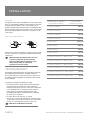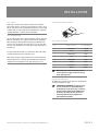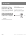
1
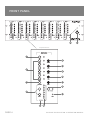
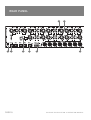
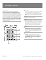
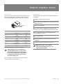
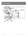
DigiPage
MULTIZONE PAGING AND SOURCE SELECTION SYSTEM
INSTALLATION AND OPERATION MANUAL
IMPORTANT SAFETY INFORMATION
1.
Save the carton and packing material even if the equipment has
arrived in good condition. Should you ever need to ship the unit,
use only the original factory packing.
2. Read all documentation before operating your equipment.
Retain all documentation for future reference.
3. Follow all instructions printed on unit chassis for proper operation.
4. Do not spill water or other liquids into or on the unit, or operate the
unit while standing in liquid.
5. Make sure power outlets conform to the power requirements listed
on the back of the unit.
6. Do not use the unit if the electrical power cord is frayed or broken.
The power supply cords should be routed so that they are not likely
to be walked on or pinched by items placed upon or against them,
paying particular attention to cords and plugs, convenience
receptacles, and the point where they exit from the appliance.
7. Always operate the unit with the AC ground wire connected to the
electrical system ground. Precautions should be taken so that the
means of grounding of a piece of equipment is not defeated.
8. Mains voltage must be correct and the same as that printed on the
rear of the unit. Damage caused by connection to improper AC
voltage is not covered by any warranty.
9. Have gain controls on amplifiers turned down during power-up to
prevent speaker damage if there are high signal levels at the
inputs.
10. Power down & disconnect units from mains voltage before making
connections.
11. Never hold a power switch in the “ON” position if it won’t stay
there itself!
12. Do not use the unit near stoves, heat registers, radiators, or other
heat producing devices
13. Do not block fan intake or exhaust ports. Do not operate
equipment on a surface or in an environment which may impede
the normal flow of air around the unit, such as a bed, rug,
weathersheet, carpet, or completely enclosed rack. If the unit
is used in an extremely dusty or smoky environment, the unit
should be periodically “blown free” of foreign matter.
14. Do not remove the cover. Removing the cover will expose you to
potentially dangerous voltages. There are no user serviceable
parts inside.
15. Do not drive the inputs with a signal level greater than that
required to drive equipment to full output.
16. Do not connect the inputs / outputs of amplifiers or consoles to
any other voltage source, such as a battery, mains source, or
power supply, regardless of whether the amplifier or console is
turned on or off.
17. Do not run the output of any amplifier channel back into another
channel’s input. Do not parallel- or series-connect an amplifier
output with any other amplifier output.
Australian Monitor Inc is not responsible for damage to
loudspeakers for any reason.
18. Do not ground any red (“hot”) terminal. Never connect a “hot”
(red) output to ground or to another “hot” (red) output!
19. Non-use periods. The power cord of equipment should be unplugged
from the outlet when left unused for a long period of time.
20. Service Information Equipment should be serviced by qualified
service personnel when:
A.
B.
C.
D.
E.
The power supply cord or the plug has been damaged.
Objects have fallen, or liquid has been spilled into the
equipment
The equipment has been exposed to rain
The equipment does not appear to operate normally,
or exhibits a marked change in performance
The equipment has been dropped, or the enclosure damaged.
THIS SAFETY INFORMATION IS OF A GENERAL NATURE AND MAY BE SUPERSEDED BY INSTRUCTIONS CONTAINED WITHIN THIS MANUAL
INTRODUCTION AND CONTENTS
The Australian Monitor Installation Series DigiPage is a 3 rack
unit multizone paging and source selection system that offers
unprecedented flexibility for multizone paging & source routing
applications.
Six program inputs and one dedicated local mic/line input are available
to each of eight zone outputs. With LED indication for program/local
input selection, zone output level, paging enable/disable and network
busy LED, the DigiPage provides extensive status indication to the user.
The DigiPage is also expandable to 16 zones via a simple link cable
to a second unit. Paging stations are available in 8 zone and 16 Zone
models allowing paging into any individual zone, any combination of
zones or All Call. Remote control panels are also available, allowing
source selection and volume control from within each remote zone.
Both the Paging stations and remote control panels connect via an
inexpensive and industry standard CAT5 cable network. An overall
priority input is also provided for emergency or evacuation signals.
The DigiPage is powered by an (included) external plug-pack power
supply or via 24VDC. The DigiPage is an incredibly versatile and well
featured product that provides a simple solution to the complex
applications of multizone paging and source routing.
We thank you for choosing Australian Monitor Installation Series
and as with all our products, the DigiPage offers clever features
and is contractor friendly.
INTRODUCTION
3
FRONT PANEL
4
REAR PANEL
6
INSTALLATION
8
DIMENSIONS
11
SETUP
12
TROUBLESHOOTING
13
LINKING TWO DIGIPAGE SYSTEMS
14
OPERATION
15
PAGING STATION
16
REMOTE CONTROL PANEL
18
BLOCK DIAGRAM
20
ACCESSORIES
21
SPECIFICATIONS
22
AUS, EUR, USA
Copyright 27th May 2003
Rev A: 27th May 2003
Rev B: 11th Aug 2004
Rev C: 13th Jan 2006
This symbol is intended to alert the user to the presence
of uninsulated “dangerous voltage” within the product’s
enclosure that may be of sufficient magnitude to
constitute a risk of electric shock to persons.
This symbol is intended to alert the user to the presence
of important operation and maintenance (servicing)
instructions in the literature accompanying the appliance.
Caution:
DIGIPAGE INSTALLATION & OPERATION MANUAL
To prevent electric shock do not use this (polarised) plug
with an extension cord, receptacle or other outlet unless
the blades can be fully inserted to prevent blade exposure.
To prevent electric shock, match wide blade of plug to
wide slot, fully insert.
PAGE 3
FRONT PANEL
5
6
Expanded View
1
6
7
2
8
9
10
3
5
4a
11
4
PAGE 4
4b
DIGIPAGE INSTALLATION & OPERATION MANUAL
FRONT PANEL
The controls detailed below (1-12) apply to each output zone, as indicated by ZONE 1 to ZONE 8 on the front panel.
1 LOCAL
5 PAGE ENABLE
This switch will turn the local input on
or off in the zone. The local input is for
exclusive use in the zone (eg Local Input 3
to Zone 3). The Local switch operates
independently of the program switches.
The local input can be mic or line;
see Rearpanel on page 6.
This switch allows the zone to be included
in or isolated from the paging stations.
You may want to do this when a zone is for
an area such as a function room that
occasionally may need to be isolated from
paging. When this button is pressed, the
adjacent green indicator lights, indicating
that the zone is able to receive paging.
2 PROG 1–6
This series of program switches
(PROG 1– PROG 6) allows the connected
program sources to be switched to the
desired zone. Program inputs may be
mic or line, see Rearpanel on page 6.
The program sources can be selected
individually, or multiple program sources
can be mixed together. Operation is
as follows:
Select one program source
Press momentarily
Add another program source
Press and hold for 2 secs
Deselect program source
Press and hold for 2 secs
Turn off all program sources
Press Prog Off
6 TREBLE
The treble control has 9dB of cut or boost
at 10kHz. The treble control affects the
entire zone.
☛
NOTE: That ‘center’ is to
the left (9 o’clock), not the top
(12 o’clock).
10 PAGE
This control adjusts the paging mic
level into the zone.
11 BUSY
This LED indicates that the control
network is busy in this zone. The zone
is currently being paged or adjusted.
Located at the right-hand end of the unit,
these controls affect all zones.
12 ON
This LED indicates there is power to
the unit.
☛
7 BASS
The bass control has 12dB of cut or boost
at 100Hz. The bass control affects the
entire zone.
☛
NOTE: That ‘center’ is to
the left (9 o’clock), not the top
(12 o’clock).
NOTE: When 24VDC emergency
power is supplied this LED will
always be on.
13 POWER
This switches power from the power
supply (included).
☛
NOTE: When 24VDC emergency
power is supplied, the unit is on
regardless of the switch position
8 LOCAL
3 PROG OFF
This switches program off in the
desired zone.
This control adjusts the level of the local
input into the zone.
9 PROG
4 MASTER 1–8
4a Up/Down
These buttons increase and decrease
the zone output level.
4b
Master volume control position indication.
☛
NOTE: This is NOT a signal level
meter. It indicates relative
volume position.
This control adjusts the overall level of all
program sources into the zone.
☛
NOTE: To balance the differing
levels of each program input, the
program trim controls on the rear
panel should be used (see rear
panel and setup sections)
DIGIPAGE INSTALLATION & OPERATION MANUAL
PAGE 5
REAR PANEL
1
8
7
PAGE 6
6
5
4
2
3
DIGIPAGE INSTALLATION & OPERATION MANUAL
REAR PANEL
PIN 1
GND
PIN 2
HOT
+
MALE XLR
PIN 3
COLD
_
3 ZONE OUTPUTS
PIN 2
HOT
+
PIN 3
COLD
-
PIN 1
GND
FEMALE XLR
1 LOCAL 1–8 INPUT SECTION
LINE The pair of RCA sockets accepts
unbalanced line level inputs. Stereo
signals are internally summed to mono.
MIC/LINE The switch selects the
sensitivity of the balanced XLR input ONLY.
Switch in: microphone level
Switch out: line level
The XLR socket accepts balanced
microphone or line level signals.
☛
NOTE: The Local Input is routed
only to the same numbered zone
output and is switched on or off
via the front panel or remote
control panel.
There is a balanced XLR line level output
for each zone.
☛
☛
NOTE: If connecting to an
unbalanced input, the negative
pin (3) should not be connected to
ground but left floating.
NOTE: When operating as a
slave unit, outputs labelled 1 to 8
will correspond to zones 9 to 16,
respectively.
(see Linking Section)
SUM INPUT LEVEL This recessed trimpot
sets the level of the sum input.
TONE GEN OUTPUT LEVEL This recessed
trim pot controls the output level of the
tones and the chime.
5 CAT 5 RUN 1–4
These RJ45 inputs accept the CAT5 cables
coming from the paging microphone
stations and the remote control panels.
See page 10 for more information.
☛
☛
NOTE: These are NOT
Ethernet connections.
NOTE: Connecting and
disconnecting these inputs
while the unit is on may cause
the unit to lock up requiring
system power to be cycled.
6 PROG LINKS
These RJ45 sockets allow linking of
the program sources when using a
Master/Slave configuration.
(see Linking Section)
☛
4 EUROBLOCK CONNECTOR
24V DC / GROUND This input pair is for
connection to a 24VDC emergency power
supply and is not switched by the front
panel power switch.
☛
NOTE: The 24V DC input does not
provide a trickle-charge facility.
NOTE: These are NOT
Ethernet connections.
7 DATA LINK
This socket is used to link two units in
a Master/Slave configuration.
(see Linking Section)
☛
NOTE: These are NOT
Ethernet connections.
8 MASTER/SLAVE
2 PROG 1–6 INPUT SECTION
LINE The pair of RCA sockets accepts
unbalanced line level inputs. Stereo
signals are internally summed to mono.
MIC The XLR socket accepts balanced
microphone level signals.
PROG GAIN The trimpot controls the
input gain of BOTH the balanced and
unbalanced program inputs.
In a Master/Slave configuration, these
also control program linked inputs.
(see Linking Section)
ALERT/EVAC/COMMON These
connections are used to trigger the
internal tones. Only one tone can be
triggered at a time. Triggering occurs by
connecting the ALERT or EVAC terminal
to COMMON.
GROUND/SUM IN This is an unbalanced
line level input which may be used for
emergency priority signals. It feeds all
outputs independent of output level
settings and page enable status.
☛
NOTE: Signal on the SUM IN will
cause other signals to be muted.
DIGIPAGE INSTALLATION & OPERATION MANUAL
This switch is used when linking 2 units in
Master/Slave configuration. (see Linking
Section)
9 POWER IN VAC
This 2.1mmx5.5mm power socket
accepts the 20VAC power supply
provided with the unit.
PAGE 7
INSTALLATION
OVERVIEW
The DigiPage features extensive flexibility in the range of input sources
that it can accommodate. In addition, the zone outputs may be used to
feed power (booster) amplifiers, mixers, mixer amplifiers etc. It is
therefore important to think about the interfacing of the DigiPage with
the other equipment if optimum performance is to be achieved. Use the
Back Panel and Specifications sections of this manual to assist with
system design.
COMBINATION OF DEVICES
ON SINGLE CAT5 RUN
MAX DISTANCE
TO END UNIT (M/FT)
1 x PAGING STATION
250m/820ft
2 x PAGING STATIONS
125m/410ft
3 x PAGING STATIONS
80m/260ft
4 x PAGING STATIONS
62.5m/205ft
1 x WALLPLATE
500m/1640ft
NOTE: XLR CONFIGURATION
PIN 2
HOT
+
PIN 1
GND
PIN 1
GND
PIN 2
HOT
+
2 x WALLPLATES
250m/820ft
3 x WALLPLATES
165m/540ft
4 x WALLPLATES
125m/410ft
1 x PAGING STATION & 1 x WALLPLATE
165m/540ft
1 x PAGING STATION & 2 x WALLPLATES
125m/410ft
1 x PAGING STATION & 3 x WALLPLATES
100m/330ft
CABLE INSTALLATION FOR PAGING
STATIONS AND REMOTE PANELS
2 x PAGING STATIONS & 1 x WALLPLATES
100m/330ft
Four RJ45 ports (labeled CAT 5 RUN 1-4) are provided for connection
to the DigiPage Zone Paging Stations and Remote wall panels.
The four ports allow for easy cable infrastructure, as CAT5 runs can
be of differing lengths depending on the installation and the number
of units connected.
2 x PAGING STATIONS & 2 x WALLPLATES
80m/260ft
3 x PAGING STATIONS & 1 x WALLPLATE
70m/230ft
PIN 3
COLD
-
FEMALE XLR
MALE XLR
PIN 3
COLD
-
When wiring the outputs on the DigiPage as unbalanced, Pin2 should
be used as hot and Pin1 as ground. Pin3 should be left open and NOT
shorted to Pin1.
☛
NOTE: If installing and terminating CAT5 cable is new
to you, please take note of the various points that
follow. As the CAT5 cabling for the DigiPage carries
voltage, damage could occur if your pin-pin
connections are not made correctly.
In planning the installation, the following rules apply:
• Up to 4 Paging Stations, remote control panels or combinations
of the two may be connected to each of the four CAT5 runs.
• Connections along the runs must be in a daisy-chain configuration.
It is acceptable to create a short branch (eg, from a wall to a
paging station). The maximum length of the branch is 10m.
• The following table indicates the maximum distance allowable
for a CAT5 run on a single port.
• For greater distances or more units, see page 10
• The last unit on a run must be terminated. This is done by moving
a jumper on the paging station or remote unit. See ‘Paging Station’
on pages 16-17 or ‘Remote Control Panel’ on pages 18-19.
☛
NOTE: These are NOT Ethernet connections.
PAGE 8
DIGIPAGE INSTALLATION & OPERATION MANUAL
INSTALLATION
CAT5 CABLE
DIGIPAGE NETWORK CABLING
CAT5 cable is the blue cable commonly used for data installations
(other colours do exist). It consists of four twisted pairs of wires: this is
why it is referred to as UTP (Unshielded Twisted Pair). The most readily
available cable uses solid conductors, like telephone wire. Cable with
stranded conductors is available, and is more flexible.
“PIN 1”
CAT5 TERMINATION
Pre-wired CAT5 cable comes in two configuration standards, 568A and
568B. It is advisable to carry a good pre-wired cable for fault-finding.
Both configurations will work with the DigiPage provided both ends
have the same configuration. Be careful not to use a crossover cable
which has one configuration at one end and the other configuration at
the other end.
Ensure that the RJ45 connectors are suited to the cable used (solid or
stranded) and that the correct crimp tool is used.
When wiring connectors, 568A standard wiring is recommended (see
diagram). Note that this is only the recommended wiring and that you
should check the configuration of any cables that you are using.
568A CONFIGURATION
PIN
WIRE COLOUR
DP NETWORK
1
White/Green
Ground
2
Green
Power
3
White/Orange
Data+
4
Blue
Busy-
5
White/Blue
Busy+
6
Orange
Data+
7
White/Brown
Voice+
8
Brown
Voice-
☛
NOTE: CAT5 cable consists of four pairs of wires:
it is not sufficient to simply wire the two ends pin
for pin, ignoring pairing.
POWER REQUIREMENTS
The DigiPage can operate from the plug pack supplied and/or
a separate 24V DC power supply.
☛
DIGIPAGE INSTALLATION & OPERATION MANUALL
A NOTE ABOUT GROUNDING: It may be necessary
in some circumstances to ground the DigiPage
to eliminate noise in the system. This can be done
using the negative terminal of the 24VDC IN euro
connector or by making sure that the chassis is
electrically connected to the equipment rack
(which should be grounded).
PAGE 9
INSTALLATION
EXTENDING CAT5 CABLE RUN DISTANCES &
PRE-ANNOUNCE CHIME
ADDING MORE PAGING STATIONS & DPRMS
The only internal setup that is available in the DigiPage is for
the configuration of the chime tone that sounds in each zone.
The unit comes shipped with the chime enabled in all zones.
The maximum distances quoted in the Table #1 are due to DC current
limitations, not data transmission limitions. If distances greater than
these are required, the paging stations and DPRM’s can be locally
powered. This will extend the maximum distances to 1000m per CAT5
RUN. Alternatively, if more than 4 paging stations or DPRM’s are required
on a single run, local powering can be used. This will increase the
maximum number of paging stations and DPRM’s on a single CAT5 RUN.
Use a regulated 12VDC supply connected as
pin1 (white/green in CAT5)- GROUND
pin2 (green in CAT5) - +12V
Disconnect incoming +V, but not ground. The 12V supply should be
rated at 150mA per paging stating being powered and 90mA per DPRM.
For further information email [email protected].
A link can be found on each zone control board at the front of
the unit (the longer board behind the zone section).
To disable the chime to a particular zone, move the link to the
upper two pins on the relevant control board. To re-enable
the chime, move the link to the lower two pins.
TONE GENERATOR INPUTS
Tones may be triggered by closing a switch or relay contact between
the selected tone trigger input and common. These trigger inputs are
5V TTL and may alternatively be triggered by pulling the desired input
low referenced to the COMMON.
NOTE: The maximum voltage on these inputs
must not exceed 5.5V
PAGE 10
DIGIPAGE INSTALLATION & OPERATION MANUAL
DIMENSIONS
DIGIPAGE INSTALLATION & OPERATION MANUAL
PAGE 11
SETUP
The inputs of the DigiPage can accommodate a wide range of sources
including active paging stations, dynamic microphones, DVD and CD
players. The zone outputs may be used to drive power (booster)
amplifiers, mixers, or mixer amplifiers.
Each installation will require setting the appropriate relative mix of
levels between paging, program sources and local inputs for each zone
and balancing between the zones.
Because of the variation in levels between the possible sources,
DigiPage offers a number of gain stage adjustment so you can set the
correct levels for your application.
Also consider what the outputs are driving …
STEP BY STEP SETUP
Confirm the initial settings of DigiPage.
Choose a zone that is conveniently located near to the DigiPage or
further away if you feel you need the exercise.
This will be the referred to as “TEST ZONE”.
Ensure that all amplifiers connected to the DigiPage are set to provide
required sound levels with a line level input signal.
Choose a consistent program source, eg CD or tuner.
This will be the referred to as “TEST PROG”.
1 Select TEST PROG in the TEST ZONE [front PROG 1-6].
Set the MASTER volume in the TEST ZONE to half way.
Setting up correct gain structure through the whole system is
important to achieve optimal results.
The following step by step procedure has been devised to assist during
the setup process.
When the DigiPage was shipped to you from the factory it was set up
in a particular way. In the following procedure it is essential that you
are starting from these initial settings.
• Program Input Gain Controls - half (12 o’clock)
• Local XLR Mic/Line switch - source dependant
• Master Volume - off
• Mic level - half (9 o’clock)
• Prog level - half (9 o’clock)
• Local level - half (9 o’clock)
2 Adjust the rear PROG GAIN for the TEST PROG input to
achieve the required sound level in the TEST ZONE.
3 Select PROG TEST in all other zones.
4 Bring up the MASTER volume in all other zones and
check for required sound levels.
5 Do a test page in the TEST ZONE and check the level relative
to the program level.
6 Adjust the page level as desired [front panel PAGE].
7 Set the input level type of any local inputs being used
[rear panel LOCAL MIC/LINE].
8 Select and check the local inputs in each zone.
Adjust the local level as desired [front panel LOCAL].
9 Balance the other program sources in the TEST ZONE
[rear panel PROG GAIN]
10 Apply the front panel settings from TEST ZONE to all other zones.
11 Using the front panel controls only set the individual zones
to your preferred settings
a. Set balance between local/prog/page
b. Set Eq
c. Set final master level
☛
PAGE 12
NOTE: A full discussion of setting up a complex system
with correct gain structure is beyond the scope of this
manual. The procedure above assumes that the installer
has correctly set up external equipment connected to
DigiPage proir to initiating the set up procedure.
DIGIPAGE INSTALLATION & OPERATION MANUAL
TROUBLESHOOTING
TROUBLE
LIKELY CAUSE
REMEDY
No response to controls
Mains brownouts or incorrect connection of
devices may cause processor to lock-up
Cycle power on the DigiPage
Poor signal to noise ratio
Incorrect system gain structure
- Check settings of all equipment
- Revisit Step-by-Step Setup Procedure
Lack of system ground
See Grounding in Installation section
Main unit set to slave
Set main unit master/slave switch to master (switch in)
LED’s chase
Initialisation (boot) sequence
Normal operation when power is applied
Inconsistent operation
Cable too long
See Installation section
Cable fault
- Check cable.
- Check Paging Station with good cable at DigiPage
Station lock-up due to connection while
system is live
With all Paging Stations connected, cycle power
on the DigiPage
No effect:busy LED blinks
Actually controlling a different zone
Program correctly (factory setting is zone 1)
Busy LED never blinks
Cable fault
- Check cable
- Check Remote Panel with good cable at DigiPage
Busy LED on
Another device has control of the zone
- Check other units
- Cycle power if suspect system lock-up
DigiPage System
All Call works but Zone Page does not
Paging Station
Emits high-pitch whine
Remote Control Panel
DIGIPAGE INSTALLATION & OPERATION MANUAL
PAGE 13
LINKING TWO DIGIPAGE SYSTEMS
DigiPage is fully expandable to form a 16 zone paging system by
the simple linking of two units. One DigiPage is then designated the
master unit, driving zones 1-8, with the slave unit driving zones 9-16.
The following settings and connections are required to form a linked
DigiPage system.
The DigiPageM16 paging station must be used to access all zones.
MASTER/SLAVE
This switches the unit from master (switch in) to slave (switch out).
When set as master the unit acts as zones 1 to 8. When set as slave
the unit acts as zones 9 to 16. This switch should only be operated
when the unit is powered off.
“PIN 1”
PROGRAM SOURCE WIRING
DATA LINK
568A CONFIGURATION
This link is essential. Use a pre-wired CAT5 patch lead.
The maximum cable length for the data link cable is 10m, but note that
PROG LINKS cable is limited to 0.5m (see below).
PIN
WIRE COLOUR
PROG WIRING
1
White/Green
Prog 1
2
Green
Prog 2
☛
☛
3
White/Orange
Prog 3
PROG LINKS
4
Blue
Prog 4
5
White/Blue
Prog 5
6
Orange
Prog 6
7
White/Brown
Ground
8
Brown
Ground
Program sources can be sent to the slave DigiPage by connecting the
PROG LINKS OUTPUT on the Master unit to the PROG LINKS INPUT on
the Slave unit. This simplifies connection of sources as all 6 sources
can be sent from the master to the slave via 1 CAT5 cable avoiding the
need for Y-cables
The PROG TRIM on the slave unit operates independently of the master
unit. The PROG TRIM on the slave unit should be set to the same
position as on the master.
Use a pre-wired CAT5 patch lead. The maximum cable length for the
program source link cable is 0.5m however this cable should be kept as
short as possible because it is carrying audio signal.
☛
☛
PAGE 14
NOTE: Maximum data link cable length is 10m
NOTE: These are NOT Ethernet connections.
NOTE: If PROG LINKS is not used, it is possible
to use completely different program sources in
zones 1-8 to zones 9-16.
NOTE: Maximum prog link cable length is 0.5m
DIGIPAGE INSTALLATION & OPERATION MANUAL
OPERATION
CHANGING VOLUME LEVELS
BUSY SIGNAL:
The output level is controlled by a digital up/down switch arrangement.
There are 32 levels from off to maximum in a non linear audio
configuration. The master LED’s indicate this volume setting but
because there are only 8 LED’s, a change to the volume (pressing
up or down) may not show a change in the LED’s. The level must
step 4 times before the LED indication changes.
When a zone is busy, the volume control and program source selection
becomes inactive. Changes cannot be made while the zone is busy.
A zone is made busy when a peripheral device is accessing the zone.
This can be in two forms:
☛
NOTE: The LED’s are an indication of master
volume setting and not an indication of signal
level or presence.
CHANGING PROGRAM SOURCES OR LOCAL:
The program sources can be selected individually, or multiple program
sources can be mixed together. Operation is as follows:
Select one program source
Press momentarily
Add another program source
Press and hold for 2 secs
Deselect program source
Press and hold for 2 secs
Turn off all program sources
Press Prog Off
1. When someone is paging to the zone. The busy led
will then glow steady.
2. When someone is making changes using the remote
wall panel. The busy led will then blink rapidly.
☛
NOTE: The paging stations for the DigiPageJr are
different to the DigiPage and cannot be mixed.
The same applies to DPRM’s which cannot be
used with the DigiPageJr.
Local is not affected and is controlled by toggling either on or off.
REMEMBERING SETTINGS / POWERING UP AND DOWN:
The DigiPage is designed to remember it’s last setting when powering
down. Due to the nature of memory storage, the unit should be left on
for at least 15 seconds after a change is made to allow the unit to store
the changes. The unit should also be allowed to stand for 15 seconds
before turning back on to allow all voltages to discharge. This is not
required if cycling the mains to clear a lockup but only to ensure that
changes are stored.
DIGIPAGE INSTALLATION & OPERATION MANUAL
PAGE 15
PAGING STATION
INTRODUCTION
1 ZONE SELECT
The Australian Monitor Installation Series DigiPage8M and
DigiPage16M Paging Stations are 8 and 16 zone paging stations
complete with a slimline gooseneck paging microphone. The Paging
stations are designed to be used with the DigiPage Zone Paging &
Source Selection System and will allow paging into any individual zone,
any combination of zones or All Call to all zones. LED indicators provide
the user with visual feedback of the zones being paged or if the zone
selected is busy. Ample label space is provided on the Paging Station,
which also provides a microphone gain control. Connection to the
DigiPage is via low cost CAT 5 cable and as with all Australian Monitor
installation products, the Paging Station provides an elegant solution
at a contractor friendly price.
CONTROLS
These buttons allow selection of zones for paging. When selected,
the adjacent LED glows green. Pressing the button again
deselects the zone. The area next to the button is for labelling the
zone. Selecting a zone does not instigate paging. See 4. ZONE
PAGE.
2 CLEAR
This button clears all the selected zones.
3 ALL PAGE
This button pages to all zones. It is momentary so must be held
while talking into the microphone. It activates the microphone and
mutes the program sources. It does NOT clear the current zone
selection configuration so the paging station will return to its
previous state (selected zones) once the ALL PAGE button is
released.
4 ZONE PAGE
5
2
3
This button pages to the current zone selection configuration as
indicated by the ZONE select LEDs. The zones being paged have
their program sources muted and the microphone becomes active.
If no zones are selected the system will still show as busy when
this button is pressed.
5 BUSY
This LED glows when the network or system is busy. This can
be caused by the local paging station (you are making a page),
another paging station, or a remote control panel being in use.
Paging is not possible while the system is busy, however zone
selections can still be made.
4
1
PAGE 16
DIGIPAGE INSTALLATION & OPERATION MANUAL
PAGING STATION
INSTALLATION AND SETUP
6 GAIN
The CAT5 cable connects to the RJ45 socket on the rear panel of the
paging station. This socket is a NEUTRIKTM connector designed to be
used with the XLR style housing (model NE8MC) to improve reliability.
Normal RJ45 connectors can also be used.
Plugging and unplugging the cable while the system is powered up
may result in the system locking up and is not recommended. If this
should happen, reset the DigiPage by switching off, then on.
To accommodate different speech levels, there is a gain control
on the base of the DigiPageM. This ships set to minimum and may
be adjusted to suit. Increasing this control too far may cause the
paging station to distort if loud or close speech levels are
encountered.
7 TERMINATING
In an RS485 network (of which the DigiPage is part of) it is
important to terminate the last device in each CAT5 RUN. Two
jumpers are provided for the data transmission and the voice
transmission to be terminated if that Paging Station is at the end
of a CAT5 RUN (see diagram).Shipped as terminated.
BASE PLATE SECTION
When making changes be sure to power off the
system and disconnect from the network.
☛
NOTE: these stations are not compatible with the
DigiPageJr network system.
6
7
Voice Data
(shown as terminated)
DIGIPAGE INSTALLATION & OPERATION MANUAL
Gain Pot
(accessible through base plate)
PAGE 17
REMOTE CONTROL PANEL
INTRODUCTION
The Australian Monitor Installation Series DPRM Remote Control Panel
is a control surface that is designed to be used with the DigiPage Zone
Paging and Source Selection System. The DPRM allows control over
program source selection, local input selection and volume control
from a remote location. LED illumination provides the user with visual
feed back if the system is busy. Connection to the DigiPage is via low
cost CAT 5 cable and as with all Australian Monitor Installation
products, the Remote Control Panel provides an elegant solution
at a contractor friendly price.
CONTROLS
All the controls correspond only to the zone for which the panel
is programmed by the installer. (see programming section)
1
1 PROG 1–6
This row of 6 buttons selects the numbered program source.
They are electrically interlocking meaning that selecting one
source will deselect the previously selected source.
2 PROG OFF
This button will turn off the program source that is
currently selected .
2
3
4
5
3 LOCAL ON/OFF
This button toggles the local input on or off.
4 BUSY
Holes for
securing cable
This LED lights when the system network is busy. The remote
control panel is disabled while the system is busy unless it is
the panel in use generating the busy indication.
Terminal block
for CAT5 wiring
5 VOLUME UP/DOWN
These two buttons increase or decrease the volume within
the zone.
6 TERMINATING
In an RS485 network (of which the DigiPage is part of) it is
important to terminate the last device in the network CAT5 RUN.
A jumper is provided for the data transmission to be terminated
if that Remote Control Panel is at the end of a CAT5 RUN.
Shipped as terminated.
PAGE 18
6
Data
(shown as terminated)
Reset Button
DIGIPAGE INSTALLATION & OPERATION MANUAL
REMOTE CONTROL PANEL
INSTALLATION
PROGRAMMING
The CAT5 cable connects to the screw terminals numbered 1-6. These
numbers correspond to the pins of the RJ45 connector on the main
unit. If following the 568A convention, the wire colours are wired as:
The following steps are for programming the remote control panel for
use in ZONE X:
1 Hold down the RESET button on the back.
2 While holding down the RESET button, hold down both the Up and
Down volume buttons.
“PIN 1”
3 Release the RESET button.
4 The remote control panel will beep 3 times indicating it is in
program mode. The BUSY LED will stay lit while in program mode.
PIN
WIRE COLOUR
DP NETWORK
5 Press the Up button X times (the unit will beep each time).
1
White/Green
Ground
2
Green
+18V
3
White/Orange
Data+
4
Blue
Busy-
5
White/Blue
Busy+ (+18V)
6
Orange
Data-
7
White/Brown
Spare
8
Brown
Spare
Eg. for ZONE 4, press 4 times
6 Press the Down button.
Ensure that the spare pair cannot short to anything.
☛
7 The BUSY LED will go out. The remote control panel is now
programmed.
8 Confirm that the panel is controlling the correct zone.
☛
NOTE: You have approx. 2 secs to begin the
programming and between button presses else
it will exit programming mode.
NOTE: If the Remote Control Panel is NOT the last
unit in the CAT5 RUN and there are paging stations
connected further down the run it is important that
the spare pair is continued to the next unit otherwise
voice information from the paging stations will not
get to the main DigiPage unit.
There are two holes available adjacent to the terminal block for
securing the CAT5 cable with a cable tie.
DIGIPAGE INSTALLATION & OPERATION MANUAL
PAGE 19
BLOCK DIAGRAM
PAGE 20
DIGIPAGE INSTALLATION & OPERATION MANUAL
ACCESSORIES
PAGING STATIONS
INPUT PLATE
8 ZONE
Cat No. DP8M
BLACK
Cat No. DPRIPB
16 ZONE
Cat No. DP16M
WHITE
Cat No. DPRIPW
REMOTE CONTROL PANELS
STANDOFF SURFACE MOUNT BOX
BLACK
Cat No. DPRMB
BLACK
Cat No. DPRMSMBB
WHITE
Cat No. DPRMW
WHITE
Cat No. DPRMSMBW
DIGIPAGE INSTALLATION & OPERATION MANUAL
PAGE 21
SPECIFICATIONS
133.0 x 483.0 x 180.5 mm
DIMENSIONS (h x w x d)
Net 6.0kg Shipping 7.0kg
Net 13.2lb Shipping 15.4lb
WEIGHT
20VAC
30VA max
POWER INPUT
PROGRAM SOURCES (trim max)
Unbalanced (RCA)
Balanced (XLR)
LOCAL SOURCE
Unbalanced (RCA)
Input Impedance:100kohm
Sensitivity: 150mV (-14dBu)
Input Impedance: 1k3ohm
Sensitivity: 1mV (-57dBu)
Min Trim: -46dB
Input Impedance: 100kohm
Sensitivity: 1.55V (+6dBu)
Balanced (XLR)
MIC
Input Impedance: 1k3ohm
Sensitivity: 11mV (-37dBu)
Input Impedance: 45kohm
Sensitivity: 350mV (-7dBu)
LINE
SUM INPUT
Input Sensitivity: 160mV (-13.5dBu)
Threshold: -46dBu (at output, indpt of input)
FREQUENCY RESPONSE (0DB/-3DB)
THD
NOISE
OUTPUT:
15Hz - 17kHz
0.005%
Page Mic: -84d
BOther Inputs: -89dB
1.5Vrms 600ohm
Max: 9Vrms
All measurements are reference to 1.5V (+6dBu)
PAGE 22
DIGIPAGE INSTALLATION & OPERATION MANUAL
AUSTRALIA AND NEW ZEALAND
www.australianmonitor.com.au
SYDNEY
MELBOURNE
BRISBANE
ADELAIDE
PERTH
AUCKLAND
(NSW & ACT SALES)
(VIC & TAS SALES)
(QLD SALES)
(SA & NT SALES)
(WA SALES)
(NZ SALES)
149 Beaconsfield
Street Silverwater
NSW 2128
Private Bag 149
Silverwater NSW 1811
Phone: (02) 9647 1411
Fax: (02) 9648 3698
Email:
[email protected]
22/277
Middleborough Road
Box Hill VIC 3128
PO Box 151 Blackburn
South VIC 3130
Phone: (03) 9890 7477
Fax: (03) 9890 7977
Email:
[email protected]
42 Commercial Road
Fortitude Valley
QLD 4006
PO Box 871 Fortitude
Valley QLD 4006
Phone: (07) 3852 1312
Fax: (07) 3252 1237
Email:
[email protected]
31 Walsh Street
Thebarton
SA 5031
PO Box 157
Hindmarsh SA 5007
Phone: (08) 8352 4444
Fax: (08) 8352 4488
Email:
[email protected]
299 Fitzgerald Street
West Perth WA 6005
PO Box 404
North Perth
WA 6906
Phone: (08) 9228 4222
Fax: (08) 9228 4233
Email:
[email protected]
Unit B, 11 Piermark
Drive Albany 1331
New Zealand
PO Box 512
Albany 1331
Phone: (09) 415 9426
Fax: (09) 415 9864
Email:
[email protected]
EUROPE/ASIA/MIDDLE EAST
USA/SOUTH AMERICA
www.australianmonitor.com.au
www.australianmonitor.com
INTERNATIONAL SALES
SENNHEISER ELECTRONIC CORPORATION
149 Beaconsfield Street Silverwater NSW 2128 Australia
Private Bag 149 Silverwater NSW 1811
Phone: 61 2 9647 1411
Fax: 61 2 9648 3698
Email: [email protected]
1 Enterprise Drive
Old Lyme CT 06371 USA
Phone: 1 860 434 9190
Fax: 1 860 434 1759
Email: [email protected]