1
Product Specifications
The TransDiscal* Probe is comprised of an electrically insulated shaft with a active
tip that functions as an electrode for RF energy delivery, a handle, tubes with luer
locks and a cable with a 5-pin connector.
The TransDiscal* Introducer includes an insulated stainless steel cannula and
a stylet.
The Tube Kit is comprised of a burette and flexible tubing fitted with luer locks
for connection to the TransDiscal* Probe.
The kit components are ethylene oxide sterilized and supplied sterile. The devices
should be stored in a cool, dry environment.
Note: Please contact Kimberly-Clark for a list of all model numbers and sizes.
Inspection Prior To Use
The sterile packaging should be visually inspected prior to use to detect any
compromise. Ensure that the packaging has not been damaged. Do not use the
equipment if the packaging has been compromised.
Equipment Required
Procedures in the disc should be performed in a specialized clinical setting
equipped with a fluoroscopy unit. The equipment required to perform RF
procedures include:
• TransDiscal* Cooled Radiofrequency Probe(s)
• TransDiscal* Cooled Radiofrequency Introducer(s)
• Cooled Radiofrequency Peristaltic Pump Unit and Cable
• Cooled Radiofrequency Sterile Tube Kit(s)
• TransDiscal* Cooled Radiofrequency Y-Connector Cable
• Dispersive Electrode
• Radiofrequency Generator (PMG-115-TD/PMG-230-TD)
Troubleshooting
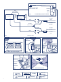
Instructions For Use (Fig. 2)
The following table is provided to assist the user in diagnosing potential
problems.
Figure 2 is a schematic representation of the connections of the system.
Assemble all the equipment required for the procedure. Set up the
Radiofrequency Generator (PMG-115-TD/PMG-230-TD) and the Pump Unit as
directed in their Instructions for Use. Connect the TransDiscal* Y-Connector Cable
to the RF Generator as described in its Instructions for Use.
Open the package in the sterile field using appropriate sterile techniques. Inspect
the devices visually to make sure there is no damage to them. Do NOT perform
the procedure with any damaged equipment.
Kimberly-Clark* TransDiscal* Cooled Radiofrequency Introducer
1. Carefully insert the Introducer with the stylet in it, into the intervertebral
disc under fluoroscopic guidance.
2. Once the Introducer is in the proper position, carefully remove the stylet
from the Introducer.
3. Repeat steps 1-2 with a second Introducer.
4
Kimberly-Clark* TransDiscal* Cooled Radiofrequency Probe
1. Insert the TransDiscal* Probes in the intervertebral disc through the
Introducers. Never force the TransDiscal* Probe in if significant resistance
is felt.
2. Connect the TransDiscal* Probe to the Tube Kit.
3. Connect the TransDiscal* Probes to the TransDiscal* Y-Connector Cable.
If the option of one TransDiscal* Probe has been enabled in the RF
Generator, connect the TransDiscal* Probe to “TransDiscal* Probe A” side
of the TransDiscal* Y-Connector Cable.
4. Select the Treatment Mode in the RF Generator. Set advanced settings
and the parameters for RF delivery in the RF Generator as described in
its User’s Manual.
5. Perform the procedure as described in the RF Generator User’s Manual.
The procedure comprises pre-cooling, treatment and post-cooling
stages.
6. Temperatures at the tip of the electrode and 3 mm proximal to the
electrode of the TransDiscal* Probe are monitored throughout the
procedure by the RF Generator.
Note: Other than reproduction of their usual back pain or irritation due
to TransDiscal* Probe introduction, monitor the patient for unexpected
symptoms that may indicate, for example, spinal cord or nerve root
irritation. If these indications are suspected discontinue energy delivery.
7. After post-cooling remove the TransDiscal* Probes and the Introducer
and discard as biohazards. If used, remove the Dispersive Electrode
from the patient and discard appropriately. Disconnect the TransDiscal*
Y-Connector Cable from the RF Generator. Follow standard hospital
techniques to handle reusable items.
Kimberly-Clark* Cooled Radiofrequency Sterile Tube Kit (Fig. 1)
1. Place the burette into the burette holder on the side of the Pump Unit.
The side of the burette with 2 or 3 ports indicates the top of the burette.
(Fig. 3)
2. Fill the burette with room temperature sterile water. Use sterile handling
techniques. Fill the burette to the 70 mL mark. Burette can be filled
by injecting sterile water through a port in the lid, or by temporarily
removing the lid and pouring sterile water in.
Warning: BE SURE TO FILL THE BURETTE TO THE 70 mL MARK.
Not filling the burette to the 70 mL mark will result in an
inadequate supply of water for circulation.
Use ONLY sterile room temperature water.
After filling, ensure the lid is snapped back onto the body of the burette
it was removed from. It is important that the lid corresponds to the
original burette body it was removed from; do not mix up the lids.
Inject sterile water into burette (Fig. 4) OR remove lid and pour sterile
water. (Fig. 5)
3. Place the thick-walled tubing coming out of the bottom of the burette
into the pumphead of the Pump Unit (Fig. 6). Place the tubing in
the channels of the L-shaped bracket to ensure that the tubing is not
obstructed while closing the pumphead. Close the lid on the pumphead
to clamp down on the tubing.
4. Remove the caps on the male and female luer locks. Connect the
appropriate luer lock to the corresponding luer lock on the TransDiscal*
Probe (Fig. 7). Do not over tighten the connection.
Caution: Connect one Tube Kit to one TransDiscal* Probe.
5. At the end of the procedure, discard the Tube Kit appropriately.
PROBLEM
TROUBLESHOOTING
No temperature
measurement in
treatment mode
OR
Inaccurate, erratic or
sluggish temperature
reading in treatment
mode
Ensure that all connections are made:
• Probe(s) to Y-Connector Cable
• Y-Connector Cable to the RF Generator
• RF Generator to power outlet
Check for an error message on the RF
Generator.
Visually inspect the Probe or Cable for
damage. Ensure that devices are dry and
at room temperature. If problem persists
discontinue use.
Water does not flow
through TransDiscal*
Probe and Tube Kit.
• Stop the procedure immediately.
• Check the luer lock connections to
ensure the Tube Kit is connected to the
TransDiscal* Probe.
• Check the Pump to ensure the lid is
not open.
• Check RF Generator for any error
messages.
Probe connector does
not fit in Probe plug-in.
• Check that the connector’s keys are lined
up in the proper orientation.
• Ensure that the connectors are clean and
unobstructed.
Damage to insulation
on TransDiscal* Probe or
Introducer.
Do not use. Discard immediately.