1
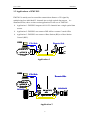
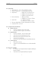
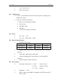
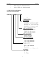
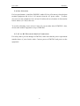
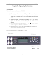
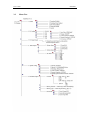
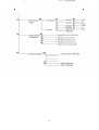
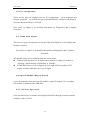
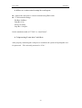
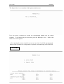
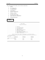
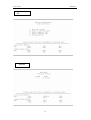
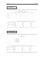
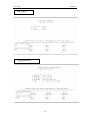
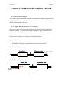
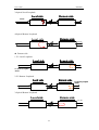
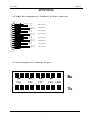
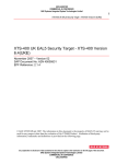
CTC Union FMUX03 Table of content Chapter 1 Introduction.……………………………………………………… 1-1 Functional Description.…………….………………………… 1 1-2 Applications of FMUX03…………………..………………… 2 1-3 FMUX03 Technical Specification………………..…………… 3 1-4 FMUX03 Ordering Information….…………………………… 6 Chapter 2 Installation…...…………………………………………………… 2-1 Description..…………..……………………………………… 7 2-2 Unpacking.…………………………………………………… 7 2-3 Site Requirements………………..…………………………… 7 2-4 Site Selection…………………………………………………. 8 2-5 DC or AC Electrical Outlet Connection……………..……….. 8 Chapter 3 Operating Instructions……………………………………………. 3-1 Front Panel……………………………………………………. 9 3-2 Front Panel Control and LED Indicator Functions………..…. 10 3-3 Menu Tree……………….…………………………………… 12 Chapter 4 Operating and Setup Instructions…………………………………. 4-1 Profile………………………………………………………… 16 4-2 E1 Configuration………………...…………………………… 16 4-3 Trunk Link Signal…………………………………………….. 16 4-4 Optical Module Manual Switch ……………………………… 16 4-5 Craft Port Operation…………………………………………... 16 4-6 Connect and setup the craft port……………………………… 17 4-7 Operating From The Craft Port……………………………….. 17 Chapter 5 Diagnostics and Loopback Functions.……….…………………… 5-1 General……………………………………………………….. 25 5-2 For E1 Tributary……………………………………………… 25 Appendix A-1. DB25 Pin Assignment for Tributary E1 Line Connection 1 A-2. Pin Assignment for Tributary E1 Pad 1 A-3. Alarm 2 i CTC Union FMUX03 Chapter 1 Introduction 1-1 Functional Description The CTC Union’s FMUX03 is a fiber optical multiplexer that integrates 4/8/16 channels of E1 signal into a single optical data stream. It extends the transmission distance up to 80 kilometer. With the optional secondary optical link, FMUX03 provides 1+1 optical line protection. In addition, FMUX03 also provides the standard SNMP interface for Network Management, using Ethernet and PPP ports to connect to central office. User can monitor the FMUX03 through built-in In-band operation channel to reach a remote terminal. Moreover, FMUX03 simplifies testing and maintenance with order wire, allowing communication between local and remote maintenance crews. The FMUX03 provides the telecommunication company a multipurpose and easy to use high quality fiber optics multiplexer. The use of FMUX03 with the Smart Agent network interface for ease of network connectivity. Provides both 10/100 Base-T and PPP interface to connect SNMP Network Management center interface system. Optional secondary fiber link offers 1+1 line auto protection to insure network quality and efficiency. In-band operation channel provides the ability to configure, test, and monitor system status and alarm from both local and remote terminal. FMUX03 offers real-time monitoring of the transmission quality to meet the demands of high quality communication. E1 signal control calculates error in Path and Line The fiber optical interface of E1 communication system complies with the requirement of ITU-T regulatory standards. Order wire to assist with remote maintenance, configuration, and testing Provides the parity error count for optical interface performance monitoring. Operating from dual AC /DC(selectable) power module (co-exist on FMUX03), backup power supply is available. Mountable on either 19-inch or 23-inch rack. 1 CTC Union FMUX03 1-2 Applications of FMUX03 FMUX03 is mainly used to extend the transmission distance of E1 signal by multiplexing four individual E1 channels into a single optical data stream. As illustrated below, there are three main applications for the use of FMUX03: ¾ Application 1: FMUX03 integrates 4/8/16 E1 channels into a single optical data stream. ¾ Application 2: FMUX03 can connect rDSLAM to a remote Central Office ¾ Application 3: FMUX03 can connect a Base Station (BS) to a Base Station Control (BSC). EMS CO. Side Remote Side 10M SDH/DACS /ATM/FR Network E1 OW N N E1 N= 4, 8, 16 Application 應用一 1 EMS CO. Side Remote Side 10M SDH/DACS /ATM/FR Network DSLAM N SNMP Agent IMA(N*E1) OW Optical Link 應用二 2 Application 2 R-DSLAM N CTC Union FMUX03 1-3 FMUX03 Technical Specifications E1 Interface ¾ Channel Capacity: 4/8/16 channels ¾ Bit Rate: 2.048Mbps +/- 50ppm ¾ Line Code: HDB3/AMI ¾ Impedance: Balanced 120Ω or Unbalanced 75Ω ¾ Electrical Interface: Conform with international standards ITU-T G.703 ¾ Jitter Tolerance: Conform with international standards ITU-T G.823 ¾ Jitter Transfer: Conform with international standards ITU-T G.742 ¾ Test Load Impedance: Balanced 120 +/- 5% Ω resistive or Unbalanced 75 +/- 5% Ω resistive Pulse Shape: Conform with ITU-T G.703 standards Nominal peak voltage of mark (pulse): +/- 3.0 Volts Nominal voltage of a space (no pulse): +/- 0.3 Volts Ratio of the amplitudes of positive and negative pulses at the nominal half amplitude: 0.95 - 1.05 Ratio of the widths of positive and negative pulses at the nominal half amplitude: 0.95 - 1.05 Nominal Pulse Width: 244ns The digital signal presented at the input port shall be as defined above but modified by the characteristic of the interconnecting pair. The ¾ ¾ attenuation of this pair shall be assumed to follow a √f law and the loss at the frequency of 1024 kHz shall be in the range of 0 to 6 dB. The minimum values for Return Loss is listed below: Frequency (kHz) Min. Return Loss Value (dB) 51 ~ 102 12 102 ~ 2048 18 2048 ~ 3072 14 Jitter generation: The jitter of the E1 output signal in the absence of input jitter shall not exceed the following limits in both bands simultaneously. Jitter output should meet the requirement after FMUX03 performs the loopback test without jitter for E1 input signal. ¾ Connector Type: DB-25 female connector 3 CTC Union FMUX03 Optical Link ¾ Wavelength: 850,1310 or 1550 nm MLM Laser diode ¾ Number of Optical Link:2 (working and protection link) ¾ Output Power: > -12dBm at 62.5/125 (850 nm Laser) >-12dBm at 9/125 (1310 nm Laser) >-12dBm at 9/125(1550 nm Laser) ¾ Receiver Sensitivity: > 0dB (Laser 850nm) >-32dBM (Laser 1310 nm or 1550 nm) ¾ System Gain: >12-14dB (Laser 850nm) >20-30dB (Laser 1310nm or 1550nm ¾ Fiber type: Single Mode (9/125um) or Multi-Mode (62.5/125um) ¾ Connectors: FC/PC , SC or ST Alarm Detection and Indication z z z Tributary Interface ¾ LOS (Loss of Signal): The loss of E1 signal ¾ AIS (Alarm Indication Signal): Alarm indicator Optical Interface ¾ LOS (Loss of Signal):The loss of optics signal ¾ LCK (Lock): Prevent switching to protect line ¾ RDI (Remote Defect Indication): Remote alarm ¾ Laser On: Laser On indicator ¾ System Power and Control Module: Normal/failure detection Alarm Connector ¾ DB-9 female connector ¾ Connect to an external BUZZER to receive visible and audible alarm. Diagnostic capabilities ¾ E1 Tributary: Local Loopback, Remote Loopback, and Request Remote Loopback. ¾ Trunk Link: Local Loopback and Remote Loopback 4 CTC Union FMUX03 ¾ ACO: Alarm cut off ¾ RST: Reset button Configuration ¾ Use the 3 control buttons and the LCD front panel to configure and monitor the system ¾ Craft port with DCE appearance ¾ Bits per second (baud): 9600bps ¾ Parity: None ¾ Data Bits: 8 bits ¾ Stop Bit: 1 (VT-100 or Emulation Terminal) Power ¾ DC: -36V ~ -72V ¾ AC: 90V ~ 288V(47Hz ~ 63Hz) Physical Specifications ¾ FMUX03 Dimensions Depth Width Height FMUX03/4 220mm 285mm 44.5mm FMUX03/8/16 440mm 285mm 44.5mm ¾ Optical Link: FC/PC or ST, Electrical Link: DB-25 female connector ¾ Order Wire: Microphone and headset ¾ Network Management Center Interface: RJ-45 and DB-9 connector ¾ Alarm Connector: DB-9 connector Environment ¾ Operating Temperature: 0 ~ 40℃ Indoor Version 0 ~ 60℃ Outdoor Version -25 ~ 70℃ Storage ¾ Humidity: 5 ~ 95% ¾ EMI: Comply with CISPR 22 standards A(EN55022) and FCC Part 15 rules. 5 CTC Union FMUX03 ¾ EMS: Comply with EN55082-2 standards ¾ Safety: Complies with EN60950 standards 1-4 FMUX03 Ordering Information Options for Ordering Information FMUX03-X XX-XXXX X-X-XX-X Optional Feature S: Surge Protection Power Module AC1: Single 90 ~ 288 VAC power supply AC2: Dual 90 ~ 288 VAC power supply DC1: Single -34 ~ -72 VDC power supply DC2: Dual -34 ~ -72 VDC power supply AD: AC/DC dual power supply Fiber Optical Connector F: FC/PC type fiber connector T: ST/PC type fiber connector S: SC/PC type fiber connector Fiber Optical Module S: Single OE module D: Dual OE module Fiber Optical Wavelength 850: 850nm multi-mode 1310: 1310nm single-mode 1550: 1550nm single-mode Interface module E1B: 120 ohm, balanced E1U: 75 ohm, unbalanced T1: 100 ohm V35: V.35 data port (single port only) Port Number 4: 4 ports 8: 8 ports 16: 16 ports 6 CTC Union FMUX03 Chapter 2 - Installation 2-1 Description This chapter provides the information needed to install FMUX03. It is important to follow the installation instruction to insure normal operation of the system and also to prevent damage due to human error. 2-2 Unpacking If there is a possibility for future relocation of the FMUX03 unit, please save the cartons and protection packaging material. The following items are shipped with your FMUX03: z z z One FMUX03 User’s Manual One FMUX03 Unit Depends on what was ordered, either DB-25 wire wrapped adaptor or DB-25 Mini Terminal Block Please carefully unpack and inspect the unit and accessories for damaged and missing parts. Contact our nearest sales representative or our company directly if you suspect any damaged or missing parts. Improper handling during shipment may cause early failure. 2-3 Site Requirements The FCC requires telecommunication equipment to withstand electrical surge that may result from lighting strikes. FMUX03 has been tested and found to comply with the FCC requirement. Users should follow the precaution below to insure the safety and minimize the risk of damage to the equipment: z Make sure that the power outlet is properly grounded. Please refer to article 250 of the National Electrical Code (NEC) Handbook. z Proper grounding should include a minimum of: 1) A grounded rod buried outside the building at least 8 feet (2.44 meters) deep. 2) It is preferred that the building uses metal water pipe and cooper connector at the joint. 2) Any device connected to FMUX03 either directly or indirectly should use the same set of power outlet. 7 CTC Union FMUX03 2-4 Site Selection For best performance, install the FMUX03 within 50 feet (656 meters) from the data terminal equipment and 6 feet (1.83 meters) from the AC power outlet. To allow easy access to the equipment, leave at least 36 inches (90 cm) clearance in front and at least 4 inches (10.2 cm) at the rear. To avoid overheating, leave at least 1 inch (2.5 cm) on either side of FMUX03. Also, do not stack another equipment on top of FMUX03. 2-5 AC or DC Electrical Outlet Connection For safety and to prevent damage to FMUX03, make sure that the power requirement matches those of your electric outlet. Connect power to FMUX03 and power on the equipment. 8 CTC Union FMUX03 Chapter 3 – Operating Instructions 3-1 Front Panel There are four parts to the front panel of FMUX03: (1) Fiber Optics Connectors and Indicators: Two sets of optics transmit/receive and indicators, one working and another as protect. Notifies user of a problem such as LOS (Loss of Signal) and Laser LED (LSR). (2) Alarm LED Display: Notifies users of a problem such as LOS (Loss of Signal) and AIS (Alarm Indication Signal) for each of the four E1 channels. (3) LCD Control Buttons: The three buttons, ▲ , ▼ , and are used for system configuration and for the loopback test. (4) Order Wire: User can connect FMUX03 to a headset and microphone for ease to remote configuration and testing. Each of the LED indicators is described below in detail: Front panel LED Display LCD Control Button Fiber Optical Connector (Working and stand by) 9 Order Wire CTC Union FMUX03 3-2 Front Panel Control and LED Indicator Functions (refrence appendix) Control or # LED Indicator Function 1 OLOS1 Red light when there is a loss of input signal OLOS2 Orange light when there is a loss of output signal LSR1/LSR2 Yellow light signals an alarm in Laser sending out energy normally 2 LOS/AIS Red light when there is a Loss of Signal (LOS) Yellow light when received an Alarm Indication Signal (AIS) 3 MAJ Red light when there is a Major Alarm present 4 MIN Yellow light when there is a Minor Alarm present 5 RNG Red light when connected to the remote terminal. 6 SYS System normal or System failure 7 RDI Remote Defect Indication; Indicates a failure in the remote terminal 8 LCK System Lock; Locks the system if switched to protect line 6 times within 10 minutes 9 ACO Alarm Cut Off; Yellow lights when the ACO button is pressed to manually disable the audible alarm when a problem occurs. If any newer alarm is reported after the ACO button has been pressed, the external alarm will activate again. 10 CAL Order wire 11 RST Restart the system 12 ▼ These three buttons serve as the control and configure ▲ FMUX03 10 CTC Union FMUX03 DB-25 pins female for E1 interface Power Switch 背板(Rear panel) Alarm (DB9) LAN PPP AC & DC Power Terminal Connector Rear panel I. E1 I/O: DB25 female connector for input/output of E1 signal II. Alarm: DB9 female connector; Connect to an external BUZZER to receive visible and audible alarm. III. Terminal Connector: LAN/PPP connector to remote terminal using RJ45. IV. Power Switches: On/Off switch for FMUX03 V. There are 5 different power supply combinations with the DC/AC dual module power supple: AC only. DC only, dual AC, dual DC, both AC and DC (Reference to Order Information) 11 CTC Union 3-3 FMUX03 Menu Tree 12 CTC Union FMUX03 13 CTC Union FMUX03 Chapter 4 - Operating and Setup Instructions FMUX03 provides easy to use LCD control for easy configuration, maintenance, and testing. Button functions are as follows: Menu select ▲ Go back to the upper level of the menu ▼ “Enter” key to go to a sub-menu 4-1 Profile Download and Save Profiles: If the user selects the factory default profile, the system will restart before downloading the factory default profile. User can configure E1 Line Code(HDB3/AMI), and Loopback test. After selecting the “user_defined” option, the system will automatically restart. The system will then download the user custom profile. Modify Password: To prevent unauthorized login, user must enter a set of password to login to the system. The password for FMUX03 is a combination of the buttons below, from left to right: Down Button Up ↑ Right → Up ↑ U R D U Password User can change the password using this function after verifying the current password. Password can also be changed from the craft terminal using the same procedure. Note that the password for operating the craft can be different from LCD menu driven is needed. Note: In case the user forgets the login password, the universal password for FMUX03 “1234” can be used. 14 CTC Union FMUX03 4-2 E1 Configuration There are two types of loopback tests for E1 configuration: Local Loopback and Remote Loopback. To perform the test on an individual E1 channel or all channels, select the function CH#(n) or CH#All. Note: Refer to Chapter 5 for detailed information on Diagnostics and Loopback Functions. 4-3 Trunk Link Signal There are two types of loopback tests for the Trunk Link Signal: Local Loopback and Remote Loopback. Note: Refer to Chapter 5 for detailed information on Diagnostics and Loopback Functions. O/E Module status can be obtained from this current menu: z Under normal operation, LCD display shows that the working O/E module as “Working” and the backup O/E Module as ”Standby.” z If FMUX03 detects a Loss of Signal, the LOS light will be lit and the LCD display will show that there is a Loss of Signal. 4-4 Optical Module Manual Switch Users can manually which between O/E module 1 and O/E module 2 if a secondary O/E module is installed on the FMUX03. 4-5 Craft Port Operation Craft port allows user to monitor and configure FMUX03 through a remote terminal emulator, such as VT100. 15 CTC Union FMUX03 4-6 How to connect and setup the craft port z Connect the craft port to a remote terminal using DB-9 cable. z VT100 terminal settings: Bit Rate: 9600bps Data Bit: 8 bit Parity: No Parity Stop Bit: 1 Stop bit Set the emulation mode to”VT100” or “Auto Detect”. 4-7 Operating From the Craft Port After properly connecting the craft port to a terminal, the system will prompt the user for password. The universal password is “1234.” 16 CTC Union FMUX03 The figure below is a screenshot of the login terminal screen: User can access a function by typing its corresponding number into the remote terminal. To go back to the previous menu, press the ‘Backspace” key. Refer to the Menu Tree for navigation. After entering the remote terminal screen, user can select Local Side operation and Remote Side operation for configuration, loopback, and monitoring of the FMUX03. Local/Re 17 CTC Union FMUX03 After entering the main menu, select of the nine functions: 1. Profile 2. E1 Configuration 3. E1 Status Report 4. Alarm Report 5. Optical Configuration 6. PM Status Report 7. PM Threshold Setting 8. Agent Network Configuration 9. System Information Main (1)-1 設定值 18 CTC Union FMUX03 E1 Alarm 19 CTC Union FMUX03 Optical PM 20 CTC Union FMUX03 PM history PM threshold 21 CTC Union FMUX03 PM report Agent network 22 CTC Union FMUX03 System 23 CTC Union FMUX03 Chapter 5 - Diagnostics and Loopback Functions 5-1 General Information This chapter contains detailed information on the diagnostics and the loopback tests of the FMUX03 fiber optics transmission equipment. User can activate the loopback function to diagnose the full service. 5-2 Loopback Functions for E1 Tributary There are two types of loopback functions for the E1 Module: Local Loopback and Remote Loopback. User can select whether to diagnose a specific channel or all channels under the “E1 Configurations” options. Figures below illustrates the concepts of the loopback function: z Local Side Loopback: Local Side Loopback tests the path between local E1 and remote E1. 1. E1 Local Loopback Local side 2. Remote side E1 AIS for any loopback channel E1 Remote Loopback Local side Remote side E1 AIS for any loopback channel 24 CTC Union FMUX03 3.Optical Local Loopback Local side Remote side All AIS 4.Optical Remote Loopback Local side Remote side All AIS z Remote side: 1. E1 Local Loopback Local side Remote side E1 AIS for any loopback channel 2. E1 Remote Loopback Local side Remote side E1 AIS for any loopback channel 3.Optical Remote Loopback Local side Remote side All AIS 25 CTC Union FMUX03 4. Optical Local Loopback Local side Remote side All AIS 26 CTC Union FMUX03 APPENDIX A-1 DB25 Pin Assignment for Tributary E1 Line Connection P1 1 14 2 15 3 16 4 17 5 18 6 19 7 20 8 21 9 22 10 23 11 24 12 25 13 GNDF TX_R2 TX_T2 RX_R2 RX_T2 RX_R1 RX_T1 GNDF GNDF TX_R1 TX_T1 TX_R4 TX_T4 RX_R4 RX_T4 RX_R3 RX_T3 TX_R3 TX_T3 Ch2 Tx pair Ch2 Rx pair Ch1 Rx pair Ch1 Tx pair Ch4 Tx pair Ch4 Rx pair Ch3 Rx pair Ch3 Tx pair DB25 female A-2 Pin Assignment for Tributary E1 pad Rx Ch1 Ch2 Ch3 Ch4 GND Tx 1 CTC Union FMUX03 A-3 Alarm Alarm Status LED sign MAJ MIN Single OE OLOSW OLOSP Dual OE OLOSW OLOS1 * OLOS2 * OLOS1 * OLOSP OLOS2 * OLOSW & OLOSP Dual PWRF1 Power PWRF2 ELOS1 ELOS2 ELOS3 ELOS4 EAIS1 EAIS2 EAIS3 EAIS4 OAIS ELOF1 ELOF2 ELOF3 ELOF4 OLOF LOC_8M LOC_2M LOC_8RM OLOS1, OLOS2 * * ELOS * * AIS * SYS ERDI ORDI RDI 2 * * CTC Union FMUX03 Fiber Optical Multiplexer Series CTC Union Technologies Co., Ltd. Far Eastern Vienna Technology Center (Neihu Technology Park) 8F, No.60, Zhouzi Street Neihu, Taipei, Taiwan Phone:(886) 2.2659.1021 Fax:(886) 2.2799.1355 E-mail: [email protected] http://www.ctcu.com 3