1
1 Summary
STS21 switch output isolation safety barrier, controls the power of safety zone with switch, drivers the field
intrinsic safety equipments of danger zone, it is applied to driver electromagnetism valve, sound and light alarm
and other small power intrinsic safety devices. The isolation of input and output, allowing control switch directly
connected to any end of 24Vdc DC power supply circuit.
2 Technical Specifications:
Channel
Single channel
Area of load
Zone 0,ⅡC,T4-6 danger zone
Zone 1, Group A,Danger zone
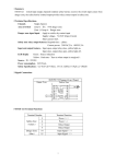
Equivalent circuit
LED display
Danger zone output
Green:Source indication
Minimum output voltage:at 45mA,12V。
Maximum output voltage: 24V。
Current limit:45mA。
Source
20~35Vdc
Power consumption
(24V Power,at 45mA Output ≤86mA)
Number of explosion-proof certificate
GYB06892
3 Safety Specifications
UO=25.2V,IO=125mA,PO=0.79W
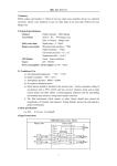
4 Signal Connections
1
5 STS21 Terminal Functions
Terminal Number
Terminal Function
Safety Zone
(Yellow)
5
Power Input(+)
6
Power Input(-)
Danger Zone
(Blue)
13
Output(+)
14
Output(-)
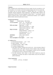
6 Dimensions
100
STS Series isolate barrier size chart
7 Installations
7.1 Guideway:Isolate barrier is installed on the standard international generic M35 Guideway.
7.2 Terminal lead:The cross-sectional area of soft copper wires which connect to field must be greater than 0.5mm2.
The insulation strength of connecting wires must be greater than 1500V.
7.3 Installation notes
a) Isolate barrier should be put in a safe place to ensure the cleaning and no corrosive gas.
b) The circuit wiring of intrinsic ends (blue) and non-intrinsic ends (yellow) of the isolate barrier is
prohibited from wrong and confusion. The intrinsic safe leads should use the blue as the marking;
intrinsic leads and non-intrinsic leads should be installed separately in the leads slot, and use different
casing tubes. The intrinsic safety side of isolate barrier is not allowed to have a mixture of other power,
including other power supply with intrinsic safety current.
c) When the isolate barriers are with concentrated layout, it should make the intrinsic side adjacent with the
intrinsic side and non-intrinsic side adjacent with the non-intrinsic side to avoid the confusion.
d) On the separate power supply debugging of isolate barrier, it is important to pay attention to the model,
power polarity, voltage grading and connector tab on the shell of isolate barriers.
e) It is forbidden to test the insulation between the terminals of isolate barrier with insulation ohmmeter, to
check the insulation of the system lines, it should disconnect all isolate barriers at first, otherwise it
would cause the fuse of internal instant fuse.
2
f) If the internal module of isolate barrier is damaged and needs replacement, it is needed to return to the
factory for repairing. The repaired isolate barriers should have a comprehensive re-examination before
being put into operation.
g) The installation, use and maintenance of isolate barrier should strictly abide by the relevant contents of
GB3836.15-2000 “Part 15 of Explosive Gas Electrical Equipment: Dangerous place electrical
installation (except mine)”, GB50058-1992 “Electrical Equipment design code of Explosion and Fire
Risk Environment” and product brochures.
8 Package and Storage
8.1 Isolate barriers should be packed with transparent plastic bags and put in the special packing boxes.
8.2 Isolate barriers should be stored in a ventilation indoor environment with ambient temperature of 5-40℃ and
relative humidity less than 85%, and without corrosive gases in the air.
8.3 Attachment
A copy of product brochure
A copy of product certification
9 Warranty
The normal product warranty period is 18 months, the damage caused by improper use is not within the scope of
warranty.
3