1
Deeter Leak Detector – User Manual
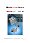
Deeter Leak Detector
© Deeter Electronics Limited
Deeter House, Valley Road, Hughenden Valley, High Wycombe, Buckinghamshire. HP14 4LW
Page 1 of 8
Deeter Leak Detector – User Manual
1. Summary
The Deeter Leak Detector comprises a Leak Detect Controller and a set of
Leak Sensors. The Controller will respond to a leak detected at any one of
the Sensors.
The Controller provides an LED indication of the system status and has relays
and a transistor output that may be used to directly drive pumps and alarms,
or may be used to interface to other equipment, such as Programmable Logic
Controllers (PLC), Building Management Systems (BMS) and dial-up alarms
systems.
The Controller has a wide range of power supply options, with separate
inputs for mains-voltage supplies (220-240VAC) and low-voltage supplies.
Low-voltage supplies can range between 8-24V AC and 10-32V DC.
A number of user-selectable options are provided by a bank of 6 switches
behind the Controller front panel. These are visible through the front panel
but are only accessible with the panel removed, so cannot accidentally be
changed.
2. Leak Detect Controller
The Leak Detect Controller is housed in a UL94-V0 flame retardant case that
will fit to standard 35mm DIN rail.
© Deeter Electronics Limited
Deeter House, Valley Road, Hughenden Valley, High Wycombe, Buckinghamshire. HP14 4LW
Page 2 of 8
Deeter Leak Detector – User Manual
2.1
Controller Electrical Connections
All electrical connections are made via two rows of screw terminals as shown
in the following table:
Top Row
Bottom
Row
Terminal No.
(left to right)
1
2
Function
Power supply input +ve
Power supply input –ve
3
4
5
Unregulated output
Alarm output (open-collector transistor)
0V
6
7
8
Leak Sensor supply output –ve
Leak Sensor input
Leak Sensor supply output +ve
Terminal No.
Function
(left to right)
1
2
3
4
5
6
7
8
Mains supply ‘Live’ (230VAC)
Mains supply ‘Neutral’
Relay 2 NO (normally-open contact)
Relay 2 COM (common contact)
Relay 2 NC (normally-closed contact)
Relay 1 NO
Relay 1 COM
Relay 1 NC
The top row (5mm spacing) has terminals grouped in twos and threes
according to function and are used for low-voltage connections only (less
than 50V). The bottom row (7.5mm spacing) may be used for connecting
mains-supply voltages (220V-240V) or low voltages if the Controller is not
powered by mains. (Mixing mains and low voltages on the bottom row of
terminals is not recommended for electrical safety reasons).
There are two pairs of power supply terminals: a low-voltage pair on the top
row and a mains voltage pair on the bottom row. Connect to one pair only.
The low voltage pair will accept AC voltages from 8V to 24V, or DC voltages
between 10V and 32V.
The unregulated output is a DC voltage derived from the supply (AC, DC or
mains) and the voltage level will depend on the supply and load. It may be
used to power external devices with return current via the 0V or ‘Alarm’
terminals.
© Deeter Electronics Limited
Deeter House, Valley Road, Hughenden Valley, High Wycombe, Buckinghamshire. HP14 4LW
Page 3 of 8
Deeter Leak Detector – User Manual
The open-collector transistor ‘Alarm’ output is current-limited to sink up to
50mA and can be pulled up to 40V. It is open during normal operation and
can be used in conjunction with the unregulated supply output to drive an
external relay. It may also be used to interface to other equipment, such as a
PLC or BMS, or it can be connected to the Leak Sensor input of another Leak
Controller to provide additional relay contacts.
The relays have a current rating of 6A at 250VAC.
2.2
LED Indicators
There are three LED indicators on the top panel: green, yellow and red.
These show the current state of the Leak Detect Controller as follows:
Operating State
System okay – no leak or line fault
Leak detected
Leak latched (leak has passed)
Fault detected
Leak latched and fault detected
2.3
Green
On
Yellow
Red
On
Flashing
On
On
Flashing
Option Switches
There are six DIP switches on the top panel, used to select a range of options.
To gain access to the switches, prise off the top panel using a flat bladed
screwdriver in the gap to the left or right-hand side of the cover.
© Deeter Electronics Limited
Deeter House, Valley Road, Hughenden Valley, High Wycombe, Buckinghamshire. HP14 4LW
Page 4 of 8
Deeter Leak Detector – User Manual
The switches have the following functions:
Switch No.
1
2
3
4
5
6
Relay 2
Alarm
Relay 1
Relay 2
Alarm
Relay1&2 default
OFF (down)
Assigned to Leak
Assigned to Leak
Follows
Follows
Follows
Off
ON (up)
Assigned to Fault
Assigned to Fault
Latches
Latches
Latches
On
Relay 1 is always assigned to leak detection.
If there is a fault detected on the Leak Sensor line, the Relay 2 output and/or
the Alarm output can be used to indicate the fault. Fault conditions include:
• A break on any of the three Leak Sensor wires
• Poor termination of the Leak Sensor wires
• Blown output fuse
The Alarm output and both relays can be set to follow a leak condition or to
latch. If following, the output will change back when conditions are dry. If
latching, the outputs will remain on, even after a leak has been cleared.
Pressing the Reset button on the top panel will unlatch the outputs and
return the Controller to its quiescent state.
Fault outputs are not latched and always return to normal once the fault
condition has been cleared. If an output is assigned to fault and also
selected to latch, the red indicator will flash after a leak has cleared. In this
configuration, although there may not be any latched outputs, a temporary
leak event can still be shown until the operator presses the reset button.
The relays can be configured to connect power or remove power to
equipment when a leak (or fault) is detected by using either the NC or NO
contacts. Switch 6 allows this choice to be based on fail-safe conditions. With
no power to the Controller, the NO contacts will be open and the NC contacts
will be connected to COM. The fail-safe configuration should be based on this
condition and the choice of whether the relays should default to on or off will
then depend on the type of equipment attached.
Example1. A pump must come on when a leak is detected but remain off if
the detector system is switched off. Use the NO contacts and set Switch 6 so
that relays default to Off.
Example 2. A siren must sound if a leak is detected or if the detector system
is switched off. Use the NC contacts and set Switch 6 so that relays default to
On.
Isolation of both supply lines may be a requirement for some mains-powered
equipment. The two single-pole relays can be used as a double-pole relay if
© Deeter Electronics Limited
Deeter House, Valley Road, Hughenden Valley, High Wycombe, Buckinghamshire. HP14 4LW
Page 5 of 8
Deeter Leak Detector – User Manual
they are both assigned to leaks and both set to latch or follow in the same
manner.
3. Leak Sensors
Leak Sensors are housed in ABS enclosures with a pair of sensing probes
protruding through the underside to detect water. The probes are stainless
steel with an M3 thread and may be extended using M3 spacers, if required.
Sensors are linked using a 3-wire cable in a daisy-chain configuration. Screw
terminals are provided for connections from the Controller (or previous
Sensor in the chain) and out to the next Sensor in the chain. The last Sensor
in the chain must terminate the wires so that if a wire becomes broken, the
Controller can detect the break and report a fault.
Sensor with lid removed showing line terminating connections
The screw terminals must be kept dry, so cables are fed through cable glands
and the box lid can be sealed to IP65. Remove the lid to reveal the screw
terminals, which have the following functions:
© Deeter Electronics Limited
Deeter House, Valley Road, Hughenden Valley, High Wycombe, Buckinghamshire. HP14 4LW
Page 6 of 8
Deeter Leak Detector – User Manual
3-way
Terminal No.
Function
Terminal 1 is close to the side
of the enclosure
1
2
3
6-way
Terminal No.
Power supply +ve
Common sensor output
Power supply –ve
Function
Terminal 1 is opposite terminal
1 on the 3-way connector
1
2
3
4
5
6
Power supply +ve
Common sensor output /
Line termination – connect
Power supply –ve
Line termination – connect
Line termination – connect
Line termination – connect
to pin 4
to pin 2
to pin 6
to pin 5
The line-termination connections are for the final Leak Sensor in the chain.
Remember to seal the unused cable gland on the final Sensor.
The Sensors have two mounting holes that can be used to bolt them to the
floor if required. The mounting holes are accessible with the lid removed.
© Deeter Electronics Limited
Deeter House, Valley Road, Hughenden Valley, High Wycombe, Buckinghamshire. HP14 4LW
Page 7 of 8
Deeter Leak Detector – User Manual
4. Specifications
Controller dimensions:
Sensor dimensions:
Sensor probes:
90mm high x 71mm wide x 58mm deep
35mm DIN rail mounting
100mm (including cable glands) x 64mm x
40mm high.
Pair, 5mm long, stainless steel, M3 thread,
spaced at 20mm centres
Mains power supply option:
Low-voltage supply option:
220VAC – 240VAC at 20mA
10VDC – 32VDC at 200mA
8VAC – 24VAC at 200mA
Relay contacts:
‘Alarm’ transistor output (resistive loads):
6A at 250VAC
Current limited to maximum 50mA
Maximum pull-up voltage, 40VDC.
Maximum number of Sensors:
Maximum cable length:
tbd (>10)
typically 2000m, depending on wire resistance
Mains supply fuse:
Low-voltage supply fuse:
Sensor output fuse:
Unregulated output fuse:
32mA anti-surge, 5x20mm cartridge
®
500mA anti-surge, Omni-Blok cartridge
®
375mA anti-surge, Omni-Blok cartridge
®
100mA anti-surge, Omni-Blok cartridge
Adinco bv
P.O.Box 90
4190 CB Geldermalsen
Netherlands
Tel. +31 (0) 345 59 60 00
Fax +31 (0) 345 59 60 01
E-mail: [email protected]
Internet: www.adinco.nl
© Deeter Electronics Limited
Deeter House, Valley Road, Hughenden Valley, High Wycombe, Buckinghamshire. HP14 4LW
Page 8 of 8