1
www.heinrichs-mt.nl
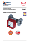
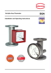
Variable-Area Flowmeters
KDS
BGK
Operating Instructions
KDS-S
KDS-K/C
BGK
KDS-R
Heinrichs Messtechnik
KDS/BGK Operating Instructions
Contents
1
Identification .................................................................................................................................. 4
1.1
Supplier/manufacturer ............................................................................................................... 4
1.2
Product type................................................................................................................................ 4
1.3
Product name.............................................................................................................................. 4
1.4
Issue date .................................................................................................................................... 4
1.5
Version no. .................................................................................................................................. 4
2
Applications ................................................................................................................................... 4
2.1
KDS und BGK ............................................................................................................................. 4
2.2
KDS-R .......................................................................................................................................... 4
3
Operational mode and system design ........................................................................................ 4
3.1
Measuring principle for BGK and KDS-K/C/S flowmeters...................................................... 4
3.2
BGK and KDS-K/C/S system design......................................................................................... 4
3.3
Measuring principle of the KDS-R ............................................................................................ 4
3.4
KDS-R system design ................................................................................................................ 4
4
Input
.......................................................................................................................................... 5
4.1
Measured variable ...................................................................................................................... 5
4.2
Measuring range......................................................................................................................... 5
4.3
Regulator range .......................................................................................................................... 5
4.4
Measuring range table ............................................................................................................... 5
5
Electrical output ............................................................................................................................ 5
1 or 2 limit transducers,............................................................................................................................ 5
6
Measuring accuracy...................................................................................................................... 5
6.1
Reference conditions ................................................................................................................. 5
6.2
Measured error ........................................................................................................................... 5
6.3
System deviation for KDS-R...................................................................................................... 5
6.4
Repeatability ............................................................................................................................... 5
6.4.1
KDS-R regulator .............................................................................................................................................................5
6.5
Influence of ambient temperature............................................................................................. 5
6.6
Influence of fluid temperature................................................................................................... 5
7
Conditions of use .......................................................................................................................... 5
7.1
7.1.1
7.2
7.2.1
7.2.2
7.2.3
7.2.4
7.2.5
7.2.6
Mounting/start-up ....................................................................................................................... 6
Device setting .................................................................................................................................................................6
Ambient conditions .................................................................................................................... 7
Ambient temperature ranges ..........................................................................................................................................7
Storage temperature.......................................................................................................................................................7
Climatic category ............................................................................................................................................................7
Degree of protection .......................................................................................................................................................7
Shock resistance/vibration resistance ............................................................................................................................7
Electromagnetic compatibility .........................................................................................................................................7
Seite 2 von 18
Heinrichs Messtechnik
7.3
Fluid conditions.......................................................................................................................... 7
7.3.1
7.3.2
7.3.3
7.3.4
7.3.5
7.3.6
7.3.7
8
KDS/BGK Operating Instructions
Fluid temperature ranges KDS-S/C/K and BGK .............................................................................................................7
Fluid temperature range KDS-R .....................................................................................................................................7
Fluid pressure limit..........................................................................................................................................................7
Inlet and outlet sections ..................................................................................................................................................7
Physical state..................................................................................................................................................................7
Pressure (for gas measurement) ....................................................................................................................................7
Pressure loss ..................................................................................................................................................................7
Construction details, type of construction/dimensions............................................................ 8
8.1
KDS-K/C....................................................................................................................................... 8
8.2
KDS-S........................................................................................................................................... 8
8.3
KDS-R with ¼“ NPT (F) connection as outlet pressure regulator version ........................... 9
8.4
KDS-R with ¼“ NPT (F) connection as inlet pressure regulator version.............................. 9
8.5
BGK with flange connection ................................................................................................... 10
8.6
Weights...................................................................................................................................... 11
8.7
Materials .................................................................................................................................... 11
8.8
Process connection ................................................................................................................. 11
9
Electrical connection .................................................................................................................. 11
9.1
Wiring diagram for limit transducer ....................................................................................... 11
10
Indicator unit................................................................................................................................ 11
11
Auxiliary power for limit switch ................................................................................................. 11
12
Available accessories ................................................................................................................. 11
13
Order information ........................................................................................................................ 11
14
Use in hazardous areas .............................................................................................................. 12
14.1
Without electrical equipment .................................................................................................. 12
14.2
With limit transducer................................................................................................................ 12
15
CE mark ........................................................................................................................................ 12
16
Standards and directives............................................................................................................ 12
17
Safety instructions ...................................................................................................................... 13
17.1
Intended use ............................................................................................................................. 13
17.2
Installation, start-up and operating personnel ...................................................................... 13
18
Packaging, mounting and shipment.......................................................................................... 13
19
Maintenance................................................................................................................................. 13
20
Trouble shooting ......................................................................................................................... 13
21
Returning devices for repair and service ................................................................................. 13
22
Decontamination certificate for device cleaning ..................................................................... 14
23
EC Type Examination Certificate of the inductive sensor ...................................................... 15
24
Notes
........................................................................................................................................ 18
Seite 3 von 18
Heinrichs Messtechnik
1
1.1
KDS/BGK Operating Instructions
3.2
Identification
The meter consists of a conical fitting pipe with a
float that can move vertically. The position of the
float resulting from the flow rate is converted to a
rotary motion on the pointer axis of the analog
indicator unit by the built-in permanent magnet
through the magnetic tracking system.
Supplier/manufacturer
Heinrichs Messtechnik GmbH
Robert-Perthel-Str. 9 ⋅ D-50739 Köln
Phone +49 (221) 49708 - 0
Fax
+49 (221) 49708 - 92
Internet: http://www.heinrichs-mt.nl
E-Mail: mailto:[email protected]
1.2
3.3
Product type
KDS-K/C/S and BGK:
Miniature flowmeter in all-metal design based on
the float principle
KDS-R:
Miniature flowmeter in all-metal design based on
the float principle with differential pressure
regulator
1.3
Product name
KDS-K/C (horizontal connection)
KDS-S (vertical connection)
KDS-R (vertical connection)
BGK (vertical flange connection)
1.4
Issue date
3.4
2.1
Applications
KDS und BGK
The KDS and BGK flowmeters are used for
measuring the flow of liquid and gaseous
products in pipes as well as dosing, monitoring,
adjusting and controlling them. They show the
current flow quantity in volume or mass per unit
in time.
2.2
KDS-R
The KDS-R flowmeter can be used for stabilizing
set flow quantities of liquid and gaseous products
in pipes. The set quantity is kept constant
independent of pressure changes during product
inflow for type KDS-R.....N or a pressure change
during product outflow for type KDS-R .....V.
3
3.1
KDS-R system design
The unit consists of a type KDS variable-area
flowmeter equipped with a differential pressure
regulator.
Version no.
3.0
2
Measuring principle of the KDS-R
Differential pressure: The diaphragm of the
regulator is in a state of equilibrium when the
pressure conditions are the same on both sides.
The pressure on the input side depends on the
pressure of the product and the pressure on the
output side on the pressure drop of the setting
valve of the flowmeter.
If the pressure changes either on the input side
or the output side, the built-in diaphragm valve
causes a pressure compensation that keeps the
set flow rate constant.
Important: The regulator can only adjust
pressure fluctuations on the input or the output
side. The pressure conditions on the respective
other side must be stable.
31/03/04
1.5
BGK and KDS-K/C/S system design
The variable-area flowmeter consists of the
device fitting made of stainless steel with an
integrated conical metal tube and a vertically
movable float. The valve for setting the flow rate
is built-in.
The height of the float resulting from the flow rate
is transmitted by the permanent magnet in the
float through the magnetic tracking system in a
rotation to the pointer axis of the analog indicator
unit.
The differential pressure regulator is made of
stainless steel and consists of a diaphragm made
of Perbunan or PTFE and a compensating valve
made of stainless steel.
Operational mode and system
design
Measuring principle for BGK and
KDS-K/C/S flowmeters
Float principle: The product flows through the
meter vertically from the bottom to the top, lifting
the float until the buoyancy force and the weight
of the float establish equilibrium. The height of
the float is a measure of the flow quantity.
Seite 4 von 18
Heinrichs Messtechnik
KDS/BGK Operating Instructions
4.2
For gaseous products, two versions are
available:
1) KDS-R...-V- for a constant inlet pressure and
a variable outlet pressure
2) KDS-R...-N- for a constant outlet pressure
and a variable inlet pressure
For liquids, both versions can be used; however,
the KDS-R...-V version is preferred.
4
4.1
Input
Measured variable
Measuring
range
Measuring
range for water
at 1000 kg/m3
0.1-1.0 l/h
0.25-2.5 l/h
0.6-6.0 l/h
1.0-10 l/h
1.6-16 l/h
2.5-25 l/h
4.0-40 l/h
6.0-60 l/h
10-100 l/h
16-160 l/h
20-200 l/h
Electrical output
1 or 2 limit transducers,
type SJ 3,5N, make Pepperl+Fuchs
(NJ 2-11 SN special switch)
Safety class: PTB 00 ATEX 2048 X
6.1
Measuring accuracy
Reference conditions
Water 20°C (air 20°C)
6.2
Measured error
± 3% of URV within the range of 10-100%
6.3
System deviation for KDS-R
± 5% of URV
6.4
Largest measuring range:
10-100 l/h water (KDS-K/C)
20-200 l/h water (KDS-S and BGK)
Regulator range
Largest regulator range:
10-100 l/h water (KDS-R)
A
B
KDS-K/C/R
C
D
KDS-S
E
F
BGK
G
H
I
only
J
KDS-S, BGK
K
*with valve completely open
6
Smallest measuring range: 0.1-1.0 l/h water
Measuring range table
Type
5
Measuring range span: 10-100%
4.3
Volume flow
4.4
Measuring range
The lower range value is considered 10% of the
upper range value.
Repeatability
± 1.0% of URV
6.4.1 KDS-R regulator
± 1.7% of URV
Measuring
Pressure loss Pressure loss Pressure loss
H2O [mbar]
range for air at H2O [mbar *] H2O [mbar*]
KDS-R
KDS-K/C
KDS-S, BGK
1.013 bars
absolute
pressure
3.0 - 30 l/h
350
6
6
7.5 - 75 l/h
350
7
7.5
18 - 180 l/h
350
7
7.5
30 - 300 l/h
350
10
8
48 - 480 l/h
350
12
9
75 - 750 l/h
350
17
10
120 - 1200 l/h
350
25
11
180 - 1800 l/h
350
45
12
300 - 3000 l/h
350
95
15
480 - 4800 l/h
20
600 - 6000 l/h
28
6.5
Influence of ambient temperature
none
6.6
Influence of fluid temperature
Deviations in fluid temperature from the
temperature observed during calibration can
result in a proportional display fault because of
the corresponding change in density. Changes in
viscosity cause a non-linear display fault.
7
Conditions of use
The VDI/VDE guidelines must be observed. The
meter is suitable for 1) liquid products with
sufficient flowability, that are free of solids, do not
bond and do not tend to settle, and 2) gases with
linear flow behavior and an adequate inlet
pressure.
KDS-R: The minimum differential pressure
between input and output side must be 350 mbar.
Page 5 of 18
Heinrichs Messtechnik
7.1
KDS/BGK Operating Instructions
Mounting/start-up
The variable-area flowmeter must be installed
perpendicularly (direction of flow from the bottom
to the top).
The size of the product line to be connected must
be identical to the size of the device connection.
Please make sure that there is adequate
clearance from parts that might cause magnetic
interferences, such as solenoid valves and
ferromagnetic components like steel
brackets/supports. We recommend that the
minimum lateral distance between two adjacently
mounted devices be 300 mm. The devices can
be mounted close together if vertically offset by
one device length. The minimum lateral
clearance for interfering steel parts should be
200 mm. In case of doubt, check the
interference by moving the device back and forth
in the selected distance by about 200 mm and
testing whether the pointer position changes.
Select the mounting location so as to enable a
reliable reading of the scale values. Please take
note as well of the space requirement for any
possible disassembly of the device.
To achieve stress-free mounting, the flanges of
the pipe must be aligned parallel to each other.
Please check whether the pipe is adequately
stable to rule out the possibility of vibration or
swinging. (Do not use steel mounting parts on the
device.)
When using gases, slowly let the inlet pressure
rise to avoid pressure surges.
Basically, avoid activation using solenoid valves
to prevent the float from shooting upwards.
KDS-S, BGK: Avoid installing a valve directly in
front of the device.
KDS-K/C: As a rule, the valve must be installed in
the output if gases are involved.
KDS-R: For gases, the version for a constant
input pressure with a valve must be installed at
the top. As an option, the version for a constant
output pressure with a valve can be installed at
the bottom. If liquids are involved, the position of
the valve does not have any impact on the
function.
7.1.1 Device setting
The measuring equipment is delivered ready for
operation according to your order specifications.
The limit transducers are set to the desired
values. If you have not submitted any
requirements, the basic settings are the following:
1 contact device: - Minimum contact switching
point at 10% of descending flow (damped/closedcircuit principle)
2 contact devices: Minimum contact switching
point at 10% of descending flow and maximum
contact switching point at 90% of ascending flow
If there is risk of dirt or solid matter penetrating
the process pipes, flush them beforehand so that
these materials do not get caught in the device.
Ferromagnetic solid matter such as spatter can
lead to the breakdown of the device. If these
materials are still present during normal operating
conditions, mount a magnetic filter (accessory) in
front of the device.
Page 6 of 18
Heinrichs Messtechnik
7.2
KDS/BGK Operating Instructions
Ambient conditions
7.2.1 Ambient temperature ranges
without limit transducer:
- 25°C to + 65°C
with limit transducer:
- 25°C to + 65°C
7.2.2 Storage temperature
- 25°C to + 65°C
7.2.3 Climatic category
Weather-protected and/or unheated locations,
class C
7.2.4
IP 65
Degree of protection
7.2.5 Shock resistance/vibration resistance
The meter should be protected from extreme
shocks and vibrations, which could cause
damage.
7.2.6 Electromagnetic compatibility
Built-in limit transducer:
In accordance with NAMUR
recommendation NE 21
EN 50 081 Part 1 / EN 50 082 Part 2
7.3
7.3.1
7.3.2 Fluid temperature range KDS-R
- 10°C to + 100°C
7.3.3 Fluid pressure limit
KDS-K/C PN 40, special version up to PN 160
KDS-S
PN 63, speceial version up to PN 320
BGK
PN 40
KDS-R
16 bar, special version up to PN 40
The maximum unilateral pressure
resistance of the diaphragm is 7 bar.
7.3.4 Inlet and outlet sections
Inlet and outlet sections are not required for a
linear flow profile of the fluid. For a non-linear
flow profile, we recommend an inlet section of
150 mm (see also guidelines in accordance with
VDI/VDE 3513).
7.3.5 Physical state
Liquid, gaseous
7.3.6 Pressure (for gas measurement)
The measured values only apply to the calibrated
fluid data stated on the scale. Any change or
deviation in pressure will cause a display fault.
Fluid conditions
Fluid temperature ranges KDS-S/C/K
and BGK
with limit transducer:
- 40°C to + 130°C
without limit transducer : - 25°C to + 100°C
7.3.7 Pressure loss
Depends on the meter size and the measuring
range (see 4.4 Measuring range table).
Page 7 of 18
Heinrichs Messtechnik
8
8.1
KDS/BGK Operating Instructions
Construction details, type of construction/dimensions
KDS-K/C
The meter consists of a conical measuring tube with a vertically movable float.
All metallic wetted parts are made of 1.4404 (316L) stainless steel.
The measured values are transmitted magnetically to the analog indicator unit mounted on the device.
KDS-K – process connections horizontally towards the back, mounting dimension:
90 mm (NPT ¼ " F connection)
KDS-C – similar to KDS-K, but with bolt for panel mounting
min 96
max 102
¼"NPT
115
90
50
Option Bolzen
für Wandaufbau
20
M5x10
SW19
15,5
78
8.2
65
KDS-S
Process connections vertically at the top/at the bottom, mounting dimension: 180 mm (NPT ¼ " F connection)
65
40
95
115
180
45
Page 8 of 18
Heinrichs Messtechnik
8.3
KDS/BGK Operating Instructions
KDS-R with ¼“ NPT (F) connection as outlet pressure regulator version
The unit consists of a variable-area flowmeter with a setting valve and a differential pressure regulator mounted
on the meter.
The measured value is displayed on the scale of the analog indicator unit.
The desired flow rate can be set using the built-in valve.
All metallic wetted parts are made of 1.4404 (316L) stainless steel.
7
60
145
+2
61
56,5
max 270
min 255
Ø105
8.4
KDS-R with ¼“ NPT (F) connection as inlet pressure regulator version
min 255
max 270
61
7
145
+2
Ø105
60
56,5
Page 9 of 18
Heinrichs Messtechnik
8.5
KDS/BGK Operating Instructions
BGK with flange connection
65
45
95
115
250
40
Page 10 of 18
Heinrichs Messtechnik
8.6
Weights
KDS-K/C
KDS-R
KDS-S
650 g
1400 g
620 g
BGK
2400 g
8.7
KDS/BGK Operating Instructions
8.8
KDS-* ¼” NPT (F)
Materials
- Measuring tube, float, connections:
1.4404 (316L) stainless steel
- Indicator unit: Polyamide
- Indicator cover: Ultramide
- Setting valve: 1.4404 (316L) stainless steel
- Valve sealing: PTFE (KDS-K/C/R)
- Tube sealing: Viton/PTFE (KDS-K/C/R/S)
- Regulator diaphragm: Perbunan/PTFE (KDS-R)
Special connections:
Ermeto 6/8/10/12/15 mm,
Swagelok 6/8/10/12 mm,
G ¼"(M), G ½“ (M),
Hose connector ¼“ (6.35 mm), available as an
adaptor.
Important: The mounting lengths may be
differerent.
Other connections are available a special
versions.
BGK:
9
9.1
Flanges: DN15/25, ANSI ¾“, 1“
Other flanges are available as special
versions.
Electrical connection
Wiring diagram for limit transducer
10 Indicator unit
-
Process connection
13 Order information
Analog indicator approx. 160° with pointer
Customized product scale
11 Auxiliary power for limit switch
Through switch amplifier
Switch amplifier is available as an accessory for
24/115/230 VAC and 24 VDC.
Please include the following information in your
order:
Product data, specific weight, temperature,
pressure, viscosity, material design, connection
size, measuring range, desired accessories,
required approvals and material certificates
12 Available accessories
1 or 2 inductive limit transducers
Page 11 of 18
Heinrichs Messtechnik
KDS/BGK Operating Instructions
14 Use in hazardous areas
Tü = Tm – Tamb = 90°C – 40°C = 50°C
14.1 Without electrical equipment
Ta = Tü*0,4+Tamb = 50°C*0.4+40°C = 60°C
The basic version of the flowmeter is a nonelectrical device without its own ignition source
and meets DIN EN 13463-1 requirements. It can
be used in hazardous areas that require
Category 2 equipment.
Marking:
II 2GD c IIB
Tech. File Ref. 03-01 X
15 CE mark
Since the device does not have its own power
sources that would result in a temperature
increase, the fluid temperature is decisive for the
maximum surface temperature.
When used in potentially explosive dust
atmospheres, the device must be cleaned
regularly in order to avoid deposits exceeding
5 mm.
14.2 With limit transducer
When the limit transducer is installed, the device
becomes an electrical assembly. The installed
limit transducer of the company Pepperl & Fuchs
is certified for the use in a explosive gas
environment by PTB 00 ATEX 2048 X EC Type
Examination Certificate and for the use in a
explosive dust environment by ZELM 03 ATEX
0128 X EC Type Examination Certificate. The
electrical and thermal data and the special
conditions of these EC Type Examination
Certificates must be observed.
Marking on
the cable of
the limit
transducer:
In accordance with the tables in the
PTB 00 ATEX 2048 X EC Type Examination
Certificate, the NJ 1,5-6,5 N... inductive sensor
must be operated in the T4 temperature class
with an intrinsically safe circuit that does not
exceed the maximum values of the Type 3 circuit.
PTB 00 ATEX 2048 X
II 2G EEx ia IIB T6-T4
ZELM 03 ATEX 0128 X
II 2D Ex iaD 20 T...°C
The measuring system meets the statutory
requirements of the following EU directives:
Directive 94/9/EC (Equipment and Protective
Systems for Use in Potentially Explosive
Atmospheres) and Electromagnetic Compatibility
(EMC) Directive 89/336/EEC.
With respect to the Pressure Equipment Directive
97/23/EC, the devices fall within the scope of
application of Article 3, Section 3, and need no
CE mark in accordance with this directive.
Heinrichs Messtechnik confirms compliance with
the directives by attaching the CE mark.
16 Standards and directives
-
-
-
The influence of the fluid temperature
on the built-in limit transducer must be
observed.
The overtemperature of the maximum
fluid temperature based on the
maximum ambient temperature must
be considered with a factor of 0.4.
Example:
Max. ambient temperature:
Max. fluid temperature:
Temperature class:
Tü =
Ta =
Overtemperature
Ambient temperature of
limit transducer
-
Tamb = 40°C
Tm = 90°C
T4
-
-
Page 12 of 18
Certified to DIN-EN 9001
Production in accordance with AD guidelines
and HPO approval (TRB200/TRD201)
TÜV approval for welding requirements in
accordance with DIN-EN 729-2
Measuring range rated and converted to
other products according to VDE/VDI
guidelines 3513
Directive 94/9/EC (Equipment and Protective
Systems for Use in Potentially Explosive
Atmospheres)
EN 50014:1997+A1-A2 - General
requirements
EN 50020:1994 - Intrinsic safety “i”
Directive 89/336/EEC (EMC Directive)
EN 61000-6-2:1999 – Immunity industrial
environment
EN 50 081-1 – Emitted interference
residential environment
EN 55011:1998+A1:1999 – Group 1, Class B
NAMUR recommendation NE 21
EN 60529 – Degrees of protection through
housing (IP code)
EN 61010 – Safety requirements for
electrical measuring, control and laboratory
devices
EN 60947-5-6:2000 – Switchgear and
controlgear
Directive 97/23/EC (Pressure Equipment
Directive)
Heinrichs Messtechnik
KDS/BGK Operating Instructions
17 Safety instructions
19 Maintenance
17.1 Intended use
The device requires no maintenance if used
according to its intended purpose. However, if
cleaning is necessary to remove dirt from the
measuring ring or the float, take note of the
following aspects:
The KDS or BGK variable-area flowmeters may
be used only for flow measurements of fluid and
gaseous media. The manufacturer shall not be
liable for damages that may result from improper
or unintended use.
When dealing with an aggressive medium, clarify
the material durability of all wetted parts.
When using the device in hazardous areas,
follow the applicable national installation rules
(see also Section 14 Use in hazardous areas).
17.2 Installation, start-up and operating
personnel
Only trained specialists authorized by the system
operator may carry out the installation, electrical
installations, start-up, maintenance and
operation. They must read and understand the
operating manual and follow its instructions.
The required mounting, electrical installation,
start-up and maintenance work may only be
carried out by expert and authorized persons
designated by the plant operator.
-
-
20 Trouble shooting
-
-
-
Basically, follow the conditions and provisions
applicable in your country.
-
18 Packaging, mounting and
shipment
Carefully unpack the device to avoid damaging it.
With the help of the delivery note enclosed in the
packaging, check whether all technically relevant
data coincide with your requirements.
Storage and installation must be done in a clean
and dry room so that contamination – especially
of the interior of the fitting – is avoided. Follow
the limit values for ambient temperature. When
transporting the device to a remote mounting
location, we recommend that you reuse the
factory-issued packaging and the transport
protection.
Before removing a device, make sure that
the pipeline is free of the product, is
pressureless and has cooled down.
Fittings with the insides coated may be
carefully cleaned after removal with a brush
and the appropriate cleansing agent.
Device shows incorrect values: Compare
process data, density, viscosity, temperature
and pressure with the values on the scale. If
they deviate, convert the scale values using
the VDE/VDI 3513 standard.
Pointer does not react in spite of varying
flow: The pointer may have gotten stuck;
remove the cover and move the pointer; if the
pointer can be moved easily, the float cannot
move. If the pointer is unable to move
further, send the device to the head office for
servicing.
The float is stuck at one place due to dirt:
Disassemble the device. If necessary,
dismantle and clean the float. Install a
magnetic filter if there are magnetic
contaminants.
Electrical equipment are not functioning:
Check the auxiliary power. Are suitable
power supply equipment connected, have the
terminals been selected correctly, has the
parameterization carried out correctly?
21 Returning devices for repair and
service
Note: In accordance with the applicable German
waste disposal legislation, the owner/client is
responsible for the disposal of special waste and
hazardous materials. Consequently, all devices
sent to us for repair must be free of any
hazardous materials. This also applies to
possible hollow spaces and fissures in the
devices. If repair is necessary, confirm the
above-mentioned item in writing (please use the
form in the Appendix).
If hazardous materials remain in or on the device
after it has been returned, Heinrichs Messtechnik
is authorized to remove them at the client’s
expense without further inquiry.
Page 13 of 18
Heinrichs Messtechnik
KDS/BGK Operating Instructions
22 Decontamination certificate for device cleaning
Company: ...............................
City: ...................................
Department: .........................
Name: ..............................
Tel: .............................
This variable-area flowmeter
Type KDS-
BGK-.........
was operated using the measured medium..................................................................
Since this measured medium is dangerous in water/poisonous/corrosive/flammable,
we have
-
checked that all hollow spaces of the device are free of these materials*
-
neutralized and flushed all hollow spaces of the device*
*cross out what is not applicable.
We hereby confirm that in resending the device no danger to persons or the environment
is posed by the residual measured substance.
Date: .............................
Signature: ...........................
Stamp
Page 14 of 18
Heinrichs Messtechnik
KDS/BGK Operating Instructions
23 EC Type Examination Certificate of the inductive sensor
Page 15 of 18
Heinrichs Messtechnik
KDS/BGK Operating Instructions
Page 16 of 18
Heinrichs Messtechnik
KDS/BGK Operating Instructions
Page 17 of 18
Heinrichs Messtechnik
KDS/BGK Operating Instructions
24 Notes
www.heinrichs-mt.nl
Tel. +31 (0) 345 596 000
Fax +31 (0) 345 596 001
[email protected]
Seite 18 von 18
Since 1970
Representative for
Heinrichs
Ein Unternehmen der IWKA Gruppe
www.heinrichs-mt.nl
Adinco bv
P.O.Box 90
4190 CB Geldermalsen
Netherlands
Tel. +31 (0) 345 59 60 00
Fax +31 (0) 345 59 60 01
E-mail: [email protected]
Internet: www.adinco.nl