1
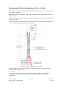
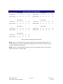
R325 Single Axis Driver
User Manual
And Commands Guide
Version 1.24
RMS Technologies
2533 N. Carson St. #4698, Carson City, NV 89706-0147
Thank you for purchasing the R325 Single-Axis Driver. This product is warranted to
be free of manufacturing defects for one (1) year from the date of purchase.
PLEASE READ BEFORE USING
Before you start, you must have a suitable step motor, a DC power supply suitable
for the motor and a current resistor. The power supply voltage must be between 4
times and 20 times the motor's rated voltage.
DISCLAIMER
The information provided in this document is believed to be reliable. However, no
responsibility is assumed for any possible inaccuracies or omissions. Specifications
are subject to change without notice.
RMS Technologies reserves the right to make changes without further notice to any
products herein to improve reliability, function, or design. RMS Technologies does
not assume any liability arising out of the application or use of any product or circuit
described herein; neither does it convey any license under its patent rights, nor the
rights of others.
Note: This equipment has been tested and found to comply with the limits for a
Class (A) digital device, pursuant to part 15 of the FCC Rules. These Limits are
designed to provide reasonable protection against harmful interferences when the
equipment is operated in its installation. This equipment generates, uses and can
radiated radio frequency energy and, if not installed and used in accordance with the
instruction manual, may cause harmful interference to radio communications. If this
equipment does cause harmful interference the user will be required to correct the
interference.
This Class (A) digital apparatus complies with Canadian ICES-003
Cet appareil numérique de la classe (A) est conforme à la norme NMB-003 du Canada
Special Symbols
Indicates a WARNING and that this information could prevent
injury, loss of property, or even death (in extreme cases).
RMS Technologies
R325 Single Axis Driver Manual
Page 2
Version 1.24
5/29/2013
R325 User Manual
Product:
Version:
Date:
R325
1.24
5/29/2013
Version History
Version
Date
Description of Changes
1.10
02/13/2006
New Formatting
1.20
6/7/2007
Added minimum inductance
1.21
8/23/2007
1.22
3/30/2009
1.23
7/7/2010
1.24
5/29/13
Added info on internal
resistors and recommended
resistors for opto-isolated
inputs.
Added Appendix B: PF
Value
Added converter card
connection
Updated error on voltage
page 8.
Updated enable/disable pin
description on page 8
RMS Technologies
R325 Single Axis Driver Manual
Page 3
Version 1.24
5/29/2013
Table of Contents
1. FEATURES ......................................................................................5
Pole Damping Technology™ ................................................................................ 5
Optically Isolated Inputs and Output .................................................................. 5
2. ELECTRICAL SPECIFICATIONS .......................................................5
3. OPERATING SPECIFICATIONS .......................................................6
4. MECHANICAL SPECIFICATIONS .....................................................6
Dimensions .................................................................................................................... 6
5. PIN ASSIGNMENTS ........................................................................7
6. CONNECTION SPECIFICATIONS .....................................................8
Connecting the Power ......................................................................................... 9
Connecting the Motor .......................................................................................... 9
Configure the R325 using the DIP Switch.......................................................... 10
DIP Switch Run Current Settings ................................................................................. 10
DIP Switch Hold Current Settings ................................................................................ 10
DIP Switch Step Resolution Settings ............................................................................ 10
7. BASIC STEP AND DIRECTION OPERATION ................................... 11
8. COMMAND TABLES....................................................................... 12
Axis Configuration Commands........................................................................... 12
General Operation Commands ........................................................................... 12
9. COMMANDS ................................................................................. 13
Protocol Syntax ................................................................................................. 13
10. Troubleshooting ........................................................................ 15
11. Appendix A ................................................................................ 16
12. Appendix B ................................................................................ 20
RMS Technologies
R325 Single Axis Driver Manual
Page 4
Version 1.24
5/29/2013
1. FEATURES
•
•
•
Single Axis Driver for Bipolar step motors
Operates from +15 to 48 VDC
Phase currents from 0.3 to 3.0 Amp Peak
NOTE: Phase current of 2.7 Amp and above REQUIRES an additional heatsink,
make sure the temperature of the bracket does not exceed 45° C.
•
•
•
•
Hold current reduction capability with adjustable current and timeout settings
Selectable Step Resolution from Full Step to 256x Microstepping
Has three optically isolated control inputs and one optically isolated control
output
Pole Damping Technology™ integrated within driver board
Dip switches and a RS485 interface are built-in to the R325 Controller. A USB
connection can be used by using the USB485 Converter Card (sold separately).
Pole Damping Technology™
Pole Damping Technology™ (PDT) enhances step motor performance by dampening
each full step in order to create a more accurate and smooth motion profile.
Microstepping the step motor will optimize Pole Damping Technology™. PDT outputs
the correct amount of run and hold currents to the motor, at the right time. Thus, it
will overcome the step motor’s natural tendency to want to forcefully pull towards
the full step ON position.
Optically Isolated Inputs and Output
The default usage of the three optically isolated inputs is Step, Direction and Disable.
The assignment of Disable is fixed; however the other two inputs can be assigned to
other functions as part of software customization. For example one can be used for
Go-Resume and the other for Stop-Quit.
The normal usage of the single optically isolated output is to indicate motion by
sending a pulse every time a step is made.
2. ELECTRICAL SPECIFICATIONS
Supply Voltage:
Phase Current:
+15 to 48 VDC
0.3 to 3.0 Amps Peak
NOTE: Phase current of 2.7 Amp and above REQUIRES an additional heatsink,
make sure the temperature of the bracket does not exceed 45° C.
I/O Specifications
3x Optically Isolated Inputs (1 fixed)
1x Optically Isolated Output
Minimum Motor Impedance: 1.5 mH
Note: The drive may behave unpredictably if the motor you are using has an inductance less
than 1.5 mH.
RMS Technologies
R325 Single Axis Driver Manual
Page 5
Version 1.24
5/29/2013
3. OPERATING SPECIFICATIONS
Maximum Step Frequency:
Operating Temperature:
2.5 MHz
Low end – 0° C
High end – Dependent on case temperature,
bracket temperature must not exceed 45° C
Automatic Motor Holding Current reduction available from 0.3 to 2.5 Amps
Logic Timing
Minimum Step Pulse Width
Minimum Step Low Time
Maximum Power-Down Recovery Time
200 nanoseconds
200 nanoseconds
20 milliseconds
4. MECHANICAL SPECIFICATIONS
Size: 3.00” x 2.94” x 1.42”
Weight: 4.8 oz
Mounting: Four #6-32 screws, 2.42” x 2.45”
Plate: Aluminum, Hard Anodized
Dimensions
RMS Technologies
R325 Single Axis Driver Manual
Page 6
Version 1.24
5/29/2013
5. PIN ASSIGNMENTS
A 12-pin pluggable terminal strip connector P1 provides power and the step and
direction control functions for the module. All of these signals are optically isolated.
Open-collector drives are required to provide pulses for Step, levels for Direction,
and Disable. The common +ve supply can be +ve 5 to 30 VDC with respect to the
signal input; however if the supply is greater than 5 VDC then a resistor must be
inserted in series with each signal line to limit the current to 10 mA.
Pin No
1
2
3
4
5
6
7
8
9
10
11
12
P1 Configuration
Function
Common +ve External
Step (in)
Direction (in)
+5 VDC Internal
Disable (in)
Motor A+ (out)
Motor A- (out)
Motor B+ (out)
Motor B- (out)
Fault (out)
Power Ground
Power Positive
P1 Connector – Pin 1 Location
CAUTION: Connecting Motor phases (A, A Bar, B, B Bar) to the incorrect location
while the R325 is powered will cause the board to burn. Be sure to insert motor
phases into Pins 6 through 9, in the order of A, A Bar, B, and B Bar. It is
recommended that power is connected last, so that all connections can be
checked before power up.
A separate three pin connector P3 is provided for the RS485 bus interface
P3 Configuration
Pin No
Function
1
A Input (+ve)
2
Ground
3
B Input (-ve)
Mating
P1
P2
P3
Connectors
Phoenix Contact
Amp
Amp
1803675
640441-5
640441-3
JP1 - Pin Header
RMS Technologies
R325 Single Axis Driver Manual
Page 7
Version 1.24
5/29/2013
6. CONNECTION SPECIFICATIONS
When using the Driver Only portion of the R325, use the dip switches for step
resolution and current settings.
Using the R325 as a Driver Unit Only
If using the R325 as a Driver only, be sure to connect the power supply last.
Pin 1: Connect Pin 1 to Pin 4 to use the internal +5VDC. By using the internal
+5VDC the I/O’s will no longer be optically isolated. If optical isolation is still
desired, use a separate +5VDC supply and connect the POSITIVE end of the supply
to Pin 1. The NEGATIVE end will connect with the NEGATIVE end of your pulse
generator.
Pin 2: Use a pulse generator or function generator to receive pulses into the R325.
Connect the POSTIVE end of the pulse generator to Pin 2. The NEGATIVE end will be
connected to the NEGATIVE end of the +5VDC supply if using a separate power
source. If using the internal +5VDC supply, connect the NEGATIVE end of the pulse
generator to Power GROUND.
Pin 3: To switch the direction of motor rotation, connect Pin 3 with Pin 11, Power
Ground. An open or closed connection to Power Ground will change the direction.
Pin 4: This is the internal +5VDC. Use this for testing purposes or if optical isolation
of the inputs is not desired. It can output a max of 50 mAmps.
Pin 5: To enable the drive leave this Pin open, disable the drive connect Pin 5 with
Pin 11 (Power Ground). An open or closed connection to Power Ground will enable
and disable the drive, respectively. A closed connection will remove all power to the
output motor leads (Pins 6 through 9).
Pin 6: Phase A Motor Connection
Pin 7: Phase A Motor Connection
Pin 8: Phase B Motor Connection
Pin 9: Phase B Motor Connection
CAUTION: Connecting Motor
phases (A, A Bar, B, B Bar) to
the incorrect location while the
R325 is powered will cause the
board to burn. Be sure to insert motor
phases into Pins 6 through 9, in the order
of A, A Bar, B, and B Bar. It is
recommended that power is connected
last, so that all connections can be
checked before power up.
Pin 10: The Fault Output is not available for the basic R325. This feature is used on
the R325I and R325IE.
Pin 11: Connect the NEGATIVE of the Power Supply to this terminal.
Pin 12: Connect the POSITIVE of the Power Supply to this terminal. (+15 to 48VDC)
RMS Technologies
R325 Single Axis Driver Manual
Page 8
Version 1.23
7/7/2010
Connecting the Power
The R325 requires a supply voltage between 15-48 VDC. First, connect the positive
end of the power supply to positive terminal (Pin 12), and then connect the negative
of the power supply to the Ground (Pin 11) on the R325.
WARNING! Be careful not to reverse the polarity from the power supply
to the driver. Reversing the connection will destroy your driver and void
the warranty.
Connecting the Motor
WARNING! Make sure the power is OFF when connecting or
disconnecting motors from the R325. Damage will occur if the
power is being supplied.
Please refer to your motor documentation for wiring color code.
Connect the corresponding Phase from the motor to the proper pin on the R325.
Motor Phase
Phase A
Phase APhase B
Phase B-
P1 Connector
Pin 6
Pin 7
Pin 8
Pin 9
Using the R325
When using the R325 in Step/Direction mode, insure that there are no jumpers on
JP1 and proceed to Section 7 – Basic Step and Direction Operation.
Using the R325 with more than 5V
You can choose to supply the optos with the R325’s internal 5V supply by jumping
pins 1 to 4. But if you choose to use more than 5V, for example, a 24V supply and
the step pulse train is also a 0 to 24V low-high signal, please use the following
recommended resistor to limit the current to 10 mAmps. Note: no resistor will be
needed on the actual opto supply line, pin 1.
Step & Direction lines have a 470 ohm internal resistor
Voltage:
5V
10V
15V
Ohms needed:
0
500
1000
Wattage rating:
0
¼ watt
¼ watt
24V
2000
¼ watt
Disable line has a 1k ohm internal resistor
Voltage:
5V
10V
Ohms needed:
0
1000
Wattage rating:
0
1/8 watt
24V
3800
¼ watt
RMS Technologies
R325 Single Axis Driver Manual
Page 9
15V
2000
1/8 watt
Version 1.23
7/7/2010
Configure the R325 using the DIP Switch
R325 DIP Switch Settings
Function
0.3A
0.4A
0.5A
0.6A
0.8A
1.0A
1.2A
1.4A
1.6A
1.8A
2.0A
2.2A
2.4A
2.6A
2.8A
3.0A
SW1
ON
OFF
ON
OFF
ON
OFF
ON
OFF
ON
OFF
ON
OFF
ON
OFF
ON
OFF
Run Current
SW2
ON
ON
OFF
OFF
ON
ON
OFF
OFF
ON
ON
OFF
OFF
ON
ON
OFF
OFF
SW3
ON
ON
ON
ON
OFF
OFF
OFF
OFF
ON
ON
ON
ON
OFF
OFF
OFF
OFF
SW4
ON
ON
ON
ON
ON
ON
ON
ON
OFF
OFF
OFF
OFF
OFF
OFF
OFF
OFF
SW9
OFF
OFF
OFF
ON
ON
OFF
OFF
ON
ON
SW10
OFF
OFF
OFF
OFF
OFF
ON
ON
ON
ON
WARNING: Current of 2.7 Amp and above REQUIRES an additional heatsink, make sure
the temperature of the bracket does not exceed 45° C
Hold Current (Percent of Run Current)
Function
SW5
SW6
0%
ON
ON
33%
OFF
ON
66%
ON
OFF
100%
OFF
OFF
Function
Full Step*
2X
4X
8X
16X
32X
64X
128X
256X
SW7
OFF
ON
ON
ON
ON
ON
ON
ON
ON
Step Resolution
SW8
OFF
OFF
ON
OFF
ON
OFF
ON
OFF
ON
*The power must be turned OFF when switching in and out of Full Step mode.
Notes:
1. Installing a jumper on JP1 pins 9 and 10 runs the factory test routine
RMS Technologies
R325 Single Axis Driver Manual
Page 10
Version 1.23
7/7/2010
7. BASIC STEP AND DIRECTION OPERATION
The four control signals Step, Direction, Disable, and Fault Out are optically isolated,
with a common positive connection (usually 5 VDC).
The common positive connection (Pin 1) is typically 5 VDC. Each of the inputs is set
to TRUE by supplying a signal level 5V below the common positive connection
powering the optical isolators. The input is set FALSE by putting the signal within 0.5
VDC below the common positive value.
Example: If 5 VDC is supplied to Pin 1 (common positive connection), TRUE is 0V,
and FALSE is any value between 4.5 VDC to 5 VDC.
For test purposes, and some applications where input isolation is not required, the
internal 5 VDC supply at Pin 4 of the I/O connector can be used as the common
positive connection, by linking pins 1 and 4 on the connector.
If this is done then each input is set TRUE by bringing the voltage level at the input
equal to, or more negative than the Power Supply negative connection at Pin 11.
With this arrangement Direction, Disable, and Fault Out control can be effected by
simple switch closure between the input and the power negative connection at Pin
11.
If the Step input is obtained from a Function Generator, then careful adjustment of
the Offset control is needed to ensure that the negative level of the input signal is
equal to, or more negative than, the power negative connection at Pin 11.
The minimum duration of the active (negative) Step input signal level is 200
nanoseconds and also this is the minimum for the inactive (positive) level. This limits
the maximum usable step rate to 2.5 MHz.
The optimum operating arrangement (minimum power usage) is for a constant width
negative going pulse of 200 nanoseconds with the pulse interval varying with pulse
rate.
For test purposes, setting the Function Generator duty cycle to 50%, and just
varying frequency is satisfactory.
RMS Technologies
R325 Single Axis Driver Manual
Page 11
Version 1.23
7/7/2010
8. COMMAND TABLES
Axis Configuration Commands
Function
Hold Timeout
Percent Fast
Decay
Query/New
Q/N
Q/N
Code
HT
PF
Value
Numeric
Numeric
Minimum
100
0
Maximum
5000
3
Default
5000
2
Maximum
-
Default
-
General Operation Commands
Function
Firmware Rev.
Query/New
Q
Code
FR
Value
Numeric
Minimum
-
Communicating with the R325
1. Place a jumper on pins 7 and 8 of JP1.
2. Communicate via RS485 with P3:
RS485-232 Converter Card:
RMS Technologies
R325 Single Axis Driver Manual
Page 12
Version 1.23
7/7/2010
USB485 Converter Card:
3. Set up HyperTerminal by selecting correct COM port
4. Settings for HyperTerminal is as follows: 57600, 8 bits, None, 1, None
2. The R325 Driver only version allows for changing the hold timeout settings,
the amount of mixed decay, and to check the firmware revision level.
9. COMMANDS (Page per Command Listing)
Protocol Syntax
Command Format: #<Address><Command><value><CR><LF>
Example:
#AHT1000<CR><LF>
Sets the Hold Timeout for Driver A to 1000
To query a command use the following format
Query Format:
#<Address><Command><CR><LF>
Example:
#AFR<CR><LF>
Queries Driver A for the current Firmware Revision
The response would be in the following format
Response Format: *<Address><value>
Example:
*AFR325100
R325 firmware revision 1.00
<CR><LF> stand for "Carriage Return" and "Line Feed" respectively. These are NOT
characters to be typed in. For direct keyboard users, these values are executed when
the "Return" key is pressed. For programmers, a "Carriage Return" and "Line
Feed" (also known as a "New Line") command needs to be executed after each
command.
RMS Technologies
R325 Single Axis Driver Manual
Page 13
Version 1.23
7/7/2010
Command
Operand
(Case Sensitive)
HT
100 -5000
Example
#AHT100
Sets the Hold
Timeout to 100
mS
PF
0-3
#ACD1
Sets Mixed
Mode damping
to 15%
FR
-
#AFR
Description
Hold Timeout - Command or Query
Default = 5000
- Reads or sets the time interval in milliseconds after any
motor movement, before the motor current is changed from
Run Current to Hold Current.
Percent Fast Decay - Command or Query
Default = 2
- Allows the Damping Mode of the driver IC to be set.
0 = Fast Decay
1 = Mixed Mode 15%
2 = Mixed Mode 48%
3 = 100%
The optimum setting will vary with motor inductance and
step rate; however the default ‘Mixed Mode’ setting will work
well with almost all motors.
Firmware Revision - Query Only
- Returns 3 digit part code followed by 3 digit firmware
revision value.
Reply
*AFR325100 //R325 firmware revision 1.00
RMS Technologies
R325 Single Axis Driver Manual
Page 14
Version 1.23
7/7/2010
10. Troubleshooting
R325 is not functioning correctly
Try putting the R325 into TEST mode by placing a jumper on Pins 9 & 10 of JP1. The
motor should twitch back and forth slightly if the R325 is functioning properly.
R325 not moving the motor (Step/Dip)
Verify that the 5V is being supplied to Pin 1.
The R325 is causing the motor to vibrate and jitter back and forth
Are the Motor phases switched? Be sure to check that motor wires are connected to
Pins 6 through 9, in the order of A, A Bar, B, B Bar. To check which wires belong to
one phase, take a Meter to measure resistance between any two wires. If there is a
finite value between two of them, insert the wires into pins 6 and 7, OR pins 8 and 9.
Insert the remaining two wires accordingly.
Technical Support
By Telephone: 408-919-0200
(Mon.-Fri., 8:00 a.m.-5:00 p.m.)
On the Web: www.linengineering.com
Our technical support group is glad to work with you in answering your questions. If
you cannot find the solution to your particular application, or, if for any reason you
need additional technical assistance, please call technical support at 408-919-0200.
RMS Technologies
R325 Single Axis Driver Manual
Page 15
Version 1.23
7/7/2010
11. Appendix A: Recommended Cable
Recommended Cable Configurations: DC Supply to Driver
Cable length, wire gauge and power conditioning devices play a major role in the performance
of your RMS Technologies Driver and Motor.
NOTE: The length of the DC power supply cable to the Driver should not exceed 50 feet.
Example A – Cabling Under 50 Feet, DC Power
Example A demonstrates the recommended cable configuration for DC power supply cabling
under 50 feet long. If cabling of 50 feet or longer is required, the additional length may be
gained by adding an AC power supply cable.
Correct AWG wire size is determined by the current requirement plus cable length. Please see
the Driver Supply Cable AWG Table in this Appendix.
RMS Technologies
R325 Single Axis Driver Manual
Page 16
Version 1.23
7/7/2010
NOTE: These recommendations will provide optimal protection against EMI and RFI. The
actual cable type, wire gauge, shield type and filtering devices used are dependent on the
customer’s application and system.
Driver Supply Cable AWG Table
1 Amp (Peak)
Length (Feet)
10
25
50*
75*
100*
Minimum AWG
20
20
18
18
16
2 Amps (Peak)
Length (Feet)
10
25
50*
75*
100*
Minimum AWG
20
18
16
14
14
3 Amps (Peak)
Length (Feet)
10
25
50*
75*
100*
Minimum AWG
18
16
14
12
12
* Use the alternative methods illustrated in Examples B and C
when the cable length is ≥ 50 feet. Also, use the same current
rating when the alternate AC power is used
Driver Supply Cable Wire Size
NOTE: Always use Shielded/Twisted Pairs for the Driver DC Supply Cable, the AC Supply
Cable and the Driver to Motor Cable.
RMS Technologies
R325 Single Axis Driver Manual
Page 17
Version 1.23
7/7/2010
Recommended Cable Configurations: Driver to Motor
Cable length, wire gauge and power conditioning devices play a major role in the performance
of your Driver and Motor.
NOTE: The length of the DC power supply cable between the Driver and the Motor should not
exceed 50 feet.
Example A demonstrates the recommended cable configuration for the Driver to Motor cabling
under 50 Feet long.
Correct AWG wire size is determined by the current requirement plus cable length. Please see
the Driver to Motor Cable AWG Table in this Appendix.
Example A - Cabling Under 50 Feet, Driver to Motor
If cabling of 50 feet or longer is required, the additional length can be gained by adding
Common Mode Line Filters (2x)
*L ≈ 0.5 MH
* 0.5 MH is a typical starting point for the Common Mode Line Filters. By increasing or
decreasing the value of L you can set the drain current to a minimum to meet your
requirements.
RMS Technologies
R325 Single Axis Driver Manual
Page 18
Version 1.23
7/7/2010
Driver to Motor Cable AWG Table
1 Amp (Peak)
5 Amp (Peak)
Length (Feet)
10
25
50
75
100
Length (Feet)
10
25
50
75
100
Minimum AWG
20
20
18
18
16
Minimum AWG
16
16
14
12
12
2 Amp (Peak)
6 Amp (Peak)
Length (Feet)
10
25
50
75
100
Length (Feet)
10
25
50
75
100
Minimum AWG
20
18
16
14
14
Minimum AWG
14
14
14
12
12
3 Amp (Peak)
7 Amp (Peak)
Length (Feet)
10
25
50
75
100
Length (Feet)
10
25
50
75
100
Minimum AWG
18
16
14
12
12
Minimum AWG
12
12
12
12
12
4 Amp (Peak)
Length (Feet)
10
25
50
75
100
Minimum AWG
18
16
14
12
12
Driver to Motor Supply Cable Wire Size
NOTE: These recommendations will provide optimal protection against EMI and RFI. The
actual cable type, wire gauge, shield type and filtering devices used are dependent on the
customer’s application and system.
NOTE: Always use Shielded/Twisted Pairs for the Driver DC Supply Cable, the AC Supply
Cable and the Driver to Motor Cable.
RMS Technologies
R325 Single Axis Driver Manual
Page 19
Version 1.23
7/7/2010
12. Appendix B: PF Value
For applications requiring ultimate smoothness of motion and extreme accuracy, the
R325 driver can be programmed via RS485 to change the Percent Fast Decay rate,
or, the PF value.
The Percent Fast Decay default is 2, or a mixed mode of 48%.
Mixed mode is a damping technique done to the driver IC. The following values
indicate the choices for Percent Fast Decay:
PF Values (0 through 4):
0 = Fast Decay
1 = Mixed Mode 15%
2 = Mixed Mode 48%
3 = 100%
Generally speaking, applications that run at slow speeds are recommended to use a
PF value of 1 or less. Fast speeds should use a PF value of 2 or more. Since the
best PF value is dependent on the motor winding, loads, power supply voltage, and
other factors, it is best to use an oscilloscope and a current probe device to view the
current waveform and try different PF values. The following examples show good
and bad waveforms when choosing different PF values.
•
•
•
PF value 1
Slow speeds
Good waveform
RMS Technologies
R325 Single Axis Driver Manual
Page 20
Version 1.23
7/7/2010
•
•
•
PF value 2
Slow speeds
Bad waveform
•
•
•
PF value 1
Fast speeds
Bad waveform
RMS Technologies
R325 Single Axis Driver Manual
Page 21
Version 1.23
7/7/2010