1
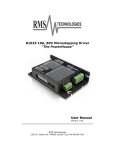
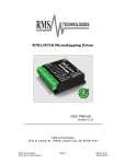
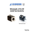
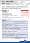
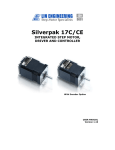
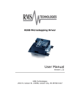
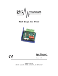
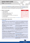
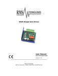
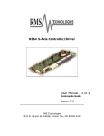
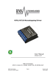
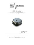
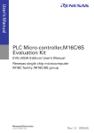
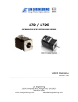
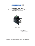
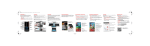
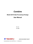
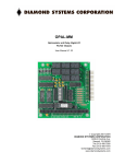
R364 3-Axis Controller/Driver
User Manual - 1 of 2
Reference Guide
Version 2.34
RMS Technologies
2533 N. Carson St. #4698, Carson City, NV 89706-0147
Thank you for purchasing the R364 3-Axis Controller/Driver. This product is warranted to
be free of manufacturing defects for one year from the date of purchase.
Technical Support for Lin Engineering, a distributor of RMS Technologies
By Telephone: 408-919-0200
(Mon.-Fri., 8:00 a.m.-5:00 p.m.)
On the Web: www.linengineering.com
Our technical support group is glad to work with you in answering your questions. If you
cannot find the solution to your particular application, or, if for any reason you need
additional technical assistance, please call technical support at 408-919-0200.
PLEASE READ BEFORE USING
Before you start, you must have a suitable step motor, a DC power supply suitable for the
motor. The power supply voltage must be between 4 times and 20 times the motor’s rated
voltage.
DISCLAIMER
The information provided in this document is believed to be reliable.
However, no
responsibility is assumed for any possible inaccuracies or omissions. Specifications are
subject to change without notice.
RMS Technologies reserves the right to make changes without further notice to any
products herein to improve reliability, function, or design. RMS Technologies does not
assume any liability arising out of the application or use of any product or circuit described
herein; neither does it convey any license under its patent rights, nor the rights of others.
RMS Technologies
R364 3-Axis Controller Driver
Page 2
Version 2.34
1/22/2008
R364 User Manual
Product: R364
Version: 2.34
Date: 1/22/2008
Version History
Version
Date
Description of Changes
2.32
09/27/2006
Old user manual
2.33
02/28/2007
2.34
01/22/2008
Standardization of user
manuals
Updated typographical
errors
RMS Technologies
R364 3-Axis Controller Driver
Page 3
Version 2.34
1/22/2008
Table of Contents
1. FEATURES 5
2. ELECTRICAL SPECIFICATIONS 6
I/O Specifications 6
Limit Switches 6
3. OPERATING SPECIFICATIONS 6
4. COMMUNICATION SPECIFICATIONS 6
5. MECHANICAL SPECIFICATIONS 7
Connectors 7
Dimensions 7
6. PIN ASSIGNMENTS 8
Location of Pin1 9
8. CONNECTION SPECIFICATIONS 11
9. HYPERTERMINAL CONFIGURATION 12
10. MULTIPLE R364 BOARDS 14
11. MOTOR CONNECTIONS 15
4 Lead Wire Motor Connection 15
6 Lead Wire Motor Connection (Half Winding) 15
6 Lead Wire Motor Connection (Full-Winding) 15
8 Lead Wire Motor Connection (Parallel Connection) 16
8 Lead Wire Motor Connection (Series Connection) 16
12. TROUBLESHOOTING 17
RMS Technologies
R364 3-Axis Controller Driver
Page 4
Version 2.34
1/22/2008
1. FEATURES
•
•
•
•
•
•
•
•
•
•
•
•
•
•
•
•
3-Axis Step Motor Controller and Driver PCB
Control up to three 2-Phase step motors
Operates from +15 to 48 VDC at up to 4.5 Amps
Phase currents between 0.2 to 1.5 Amp/Phase (Software Programmable)
Step profiles - Trapezoidal, Velocity, Smooth Stop
Up to 15.6 kHz Full Step Frequency (All motors moving)
Full Step, Half Step, 1/4, 1/8, 1/16, 1/32, and 1/64 step resolution
Three level smart current control– Accelerating/Decelerating, Constant Speed, Zero
Speed
Operating modes - Host Control or Joystick
Command format - ASCII Character Strings
All configuration parameters and a script of up to 1,750 commands
Limit switches - Left and Right switch inputs for all motors
Home reference - Commanded automatic sequence for each motor. The Left Limit
Switch is found. The motor then moves to a user given offset position, and then sets
the current position to be zero.
Analog/Digital Inputs - Eight inputs 0 to 5 VDC analog, or eight inputs TTL digital
Digital Outputs - Seven open-collector relay or solenoid drivers, and one TTL output
Stores parameters such as current, microstep, top speed in a non-volatile memory
location
Figure 1: R364 Simplified Block Diagram
RMS Technologies
R364 3-Axis Controller Driver
Page 5
Version 2.34
1/22/2008
2. ELECTRICAL SPECIFICATIONS
Supply Voltage:
Peak Current:
+15 to 48 VDC @ up to 4.5 Amps
0.2 to 1.5 Amps for each axis (Software Programmable)
Main Power – The lower limit of 15V is set by the driver IC ratings. The on-board voltage
regulator determines the upper limit of 48V. The maximum current draw with all three
motors shutdown (zero current) is less than 100 mA
I/O Specifications
Analog/Digital Inputs:
Digital Outputs:
Eight inputs 0 to 5 VDC analog, or eight inputs TTL Digital
Seven open-collector relay or solenoid drivers, and one TTL
output
Limit Switches
There are left and right limit switches for each axis. The limit switches must be pulled
to ground in order to begin using the axes. Motors will not respond to moves if limit
switches are high.
3. OPERATING SPECIFICATIONS
Maximum Step Frequency
Operating Temperature
Up to 15.6 kHz Full Step frequency (all motors moving)
0° to 50° Celsius (ambient)
4. COMMUNICATION SPECIFICATIONS
Both RS232 and RS485 are supported, but only one can be used at a time. Address bytes
in the RS485 commands allow multiple units (30 axis max) to be controlled from a single
host port.
Interface Type
Baud Rate
# Bits per character
Parity
Stop Bit
Flow Control
RS232 or RS485
Standard rates in the range 9600 to 57600 bits per second
8 data bits
None
2
None
Note: JP4 must be switched to the corresponding communication specification (either RS232
or RS485). When using RS485 with multiple modules, be sure to terminate the last board
using a jumper on JP5.
JP4 needs to have a jumper on Pins 1 & 2 if you are communicating via RS485. JP4 needs
to have a jumper on Pins 2 & 3 if you are communicating via RS232.
RMS Technologies
R364 3-Axis Controller Driver
Page 6
Version 2.34
1/22/2008
5. MECHANICAL SPECIFICATIONS
Size & Weight: 3.209” x 6.398” (81.50 mm x 162.50 mm), 3.6 oz (100 gm)
Mounting: Four #6-32 screws, 2.700” x 6.100” (68.58 mm x 154.94 mm)
Connectors
1. RS232 is a DB9 female connector. A DB-9 to DB-9, male to female cable is required
to plug this into a PC
2. RS485, SA CTL & Fault (stand-alone control), Motors 1, 2, 3 are IDC (insulation
displacement connector) Pin headers with 0.1” (2.54 mm) pin to pin pitch. Use AMP
part number 770602-XX, where the XX stands for the # of pinouts. For motor
connectors there are 8 pins so part number is 770602-8.
3. Power is a 3.81 mm Pluggable Terminal.
4. Digital outputs and digital/analog inputs (J6 and J7) use an AMP part number
770602-10 for the connector and 770666-1 for the pins.
5. A jumper is provided for the RS232/485 selection, but no jumper is provided in the
RS485 Terminal. If you only have one unit, no jumper is needed. If you have
multiple units, a jumper will be needed on the last module.
Dimensions
JP4
JP5
(Internal use)
S1
Reset Button
J4
JP2
JP3
J1
J2
J3
J5
Figure 2: Dimensions Diagram
RMS Technologies
R364 3-Axis Controller Driver
Page 7
Version 2.34
1/22/2008
6. PIN ASSIGNMENTS
Main Power – The lower limit of 15V is set by the driver IC ratings. The on-board voltage
regulator determines the upper limit of 48V. The maximum current draw with all three
motors shutdown (zero current) is less than 100 mA
CON J5
1
2
Ref.
GND
VDD
Function
Power Return
Main Power (15 to 48 VDC)
RS232 – The baud rate for either RS232 or RS485 can be set at standard rates in the range
9,600 to 57,600 baud. The format used is 8 data bits, no parity, 2 stop bits.
CON J4
2
3
5
Ref.
TXD
RXD
GND
Function
RS232 TXD
RS232 RXD
Signal GND
RS485 – Both RS232 and RS485 are supported but only one can be used. Address bytes in
the RS485 commands allow multiple units (30 axis max) to be controlled from a single host
port
CON J8
1
2
3
Ref.
RS485+
GND
RS485-
Function
RS485 TX/RX A
Signal GND
RS485 TX/RX B
RS232/RS485 Terminal – Place the jumper on Pins 1 & 2 if you want to communicate via
RS485 (and place a jumper on JP5 for the last board in the line). Place the jumper on Pins
2 & 3 if you are communicating on RS232.
CON J4
1
2
3
Ref.
RS485
Comm.
RS232
Function
Use pins 1 & 2 for RS485
Use pins 2 & 3 for RS232
Opto-Isolators – Provision is made to accept Step and Direction inputs via standard optoisolators. Requires 10 to 15 mA from a +5 VDC supply for each input
CON JP3
15
16
17
18
19
20
RMS Technologies
R364 3-Axis Controller Driver
Ref.
OI1G
OI1S
OI2G
OI2S
GND
FLT
Function
Opto-Isolator
Opto-Isolator
Opto-Isolator
Opto-Isolator
Signal GND
Fault
Page 8
1
1
2
2
Ground
Signal
Ground
Signal
Version 2.34
1/22/2008
Limit Switches – The limit switch inputs can be from mechanical switches (Contact closure
to ground with 10K pull-ups) or from optical or magnetic sensors with logic level outputs
CON J1
Ref.
Function
1
AVCC
+5VDC
2
RS1
Right Switch 1*
3
4
5
6
7
8
LS1
GND
M1BM1AM1B+
M1A+
Left Switch 1*
Ground
Motor 1 Phase
Motor 1 Phase
Motor 1 Phase
Motor 1 Phase
B
A
B
A
+
+
CON J2
1
2
3
4
5
6
7
8
Ref.
AVCC
RS2
LS2
GND
M2BM2AM2B+
M2A+
Function
+5VDC
Right Switch 2*
Left Switch 2*
Ground
Motor 2 Phase B
Motor 2 Phase A
Motor 2 Phase B
Motor 2 Phase A
+
+
CON J3
1
2
3
4
5
6
7
8
Ref.
AVCC
RS3
LS3
GND
M3BM3AM3B+
M3A+
Function
+5VDC
Right Switch 3*
Left Switch 3*
Ground
Motor 3 Phase B
Motor 3 Phase A
Motor 3 Phase B
Motor 3 Phase A
+
+
*NOTE: In order to first get the R364 running, all limit switches must be timed to ground.
On all 3 axes, tie pins 2, 3, and 4 together.
Location of Pin1
The location of pin 1 is always where the silkscreen label is located. Follow image below:
RMS Technologies
R364 3-Axis Controller Driver
Page 9
Version 2.34
1/22/2008
7. INPUTS & OUTPUTS
Analog VCC – A filtered output from the on-board voltage regulator (0.5 mA max).
Analog Inputs – Voltage signals in the range 0 to 5 VDC can be read via the
microcontroller 10 bit ADC, or these pins can be set for logic signal input by user software
CON J6
1
2
3
4
5
6
7
8
9
10
Ref.
AVCC
GND
ADC0
ADC1
ADC2
ADC3
ADC4
ADC5
ADC6
ADC7
Function
Analog VCC
Ground
Analog In 0
Analog In 1
Analog In 2
Analog In 3
Analog In 4
Analog In 5
Analog In 6
Analog In 7
(+5v Ref)
(Or
(Or
(Or
(Or
(Or
(Or
(Or
(Or
TTL
TTL
TTL
TTL
TTL
TTL
TTL
TTL
Logic
Logic
Logic
Logic
Logic
Logic
Logic
Logic
In)
In)
In)
In)
In)
In)
In)
In)
Logic VCC – A direct output from the on-board voltage regulator. Maximum current
draw should be less than 150 mA
Digital Out – Logic level outputs under user software control
CON J7
1
2
3
4
5
6
7
8
9
10
RMS Technologies
R364 3-Axis Controller Driver
Ref.
VCC
GND
OUT0
OUT1
OUT2
OUT3
OUT4
OUT5
OUT6
OUT7
Function
Logic VCC
Ground
Digital Out
Digital Out
Digital Out
Digital Out
Digital Out
Digital Out
Digital Out
Digital Out
Page 10
0
1
2
3
4
5
6
7
Version 2.34
1/22/2008
8. CONNECTION SPECIFICATIONS
List of Parts:
•
•
•
•
•
R364 3-Axis Controller/Driver
RS232 Serial Cable (DB9, male to female cable) and Motor Cables
PC
Power supply +15 to 48 VDC
1-3 Bipolar 2-phase step motors
Follow the schematic for correct connection:
Figure 3: Connection Diagram
RMS Technologies
R364 3-Axis Controller Driver
Page 11
Version 2.34
1/22/2008
9. HYPERTERMINAL CONFIGURATION
Using HyperTerminal to first get motors running; go to (Windows 98 or newer):
Start Menu Æ Programs Æ Accessories Æ Communications Æ HyperTerminal.
1. Name your new connection and
select an icon.
Click ‘OK’
2. Then select the correct connection
that the R364 is connected to, i.e.
COM1.
Click ‘OK’
RMS Technologies
R364 3-Axis Controller Driver
Page 12
Version 2.34
1/22/2008
3. Select the correct settings:
Bits per second:
Data bits:
Parity:
Stop Bits:
Flow Control:
Click ‘OK’
4. Now go to File Æ Properties
Click the ‘Settings’ tab.
Then click on ‘ASCII Setup’.
Check the ‘Send line ends with line
feeds’ box. Click ‘OK’
Now, you are ready to program the
R364 controller.
When finished using HyperTerminal,
you can save your settings when
prompted.
57600
8
None
2
None
10. MULTIPLE R364 BOARDS
Multiple R364 modules can be controlled from a single computer port. Each module is
assigned a unique address character, and the RS485 bus ports are wired in parallel.
The individual can be widely distributed (up to 500 ft) or stacked side by side.
RS232 to RS485 and USB to RS485 adapters are available from several sources.
Figure 4: Multiple R364 Configuration Diagram
RMS Technologies
R364 3-Axis Controller Driver
Page 14
Version 2.34
1/22/2008
11. MOTOR CONNECTIONS
Step Motors have 4, 6, or 8 wires. To better understand how to connect your step
motor with your R364 Driver, follow the Figures below for the corresponding motor.
NOTE: The dots indicate the starting position of the wires when wound.
4 Lead Wire Motor Connection
Connect one set of windings to the A terminals. Connect the other set of windings to
the B terminals. If the set of windings is unclear, take a pair of wires; use an
ohmmeter to check for continuity. When you find the first two wires that have
continuity, connect it to the A terminals. Connect the other two to the B terminals.
Figure 8.1: 4 Lead Wire Motor Connection
6 Lead Wire Motor Connection (Half Winding)
Six wire motors can be wound in two ways: Half Winding and Full Winding. Six wire
motors contain a center tap on each of the two windings. For a half-winding
connection, the center tap and one end of the wires are used. (Also called Half-coil)
Figure 8.2: 6 Lead Wire Half Winding Connection
6 Lead Wire Motor Connection (Full-Winding)
RMS Technologies
R364 3-Axis Controller Driver
Page 15
Version 2.34
1/22/2008
For a full winding connection, use both end wires, the center tap is ignored. (NC: No
Connection). Also known as series connection.
Figure 8.3: 6 Lead Wire Full Winding Connection
8 Lead Wire Motor Connection (Parallel Connection)
Eight wire motors can be connected in two ways: Parallel and Series. When in
parallel, the wires are simply connected such that the beginning of each winding are
connected together.
Figure 8.4: 8 Lead Wire Parallel Connection
8 Lead Wire Motor Connection (Series Connection)
Be sure to set the drive current to exactly half of the motor’s rated parallel current
rating when using the series connection.
Figure 8.5: 8 Lead Wire Series Connection
RMS Technologies
R364 3-Axis Controller Driver
Page 16
Version 2.34
1/22/2008
12. TROUBLESHOOTING
Why aren’t my motors spinning?
Make sure that if you are not using the reference switches that you have them tied
to ground.
RMS Technologies
R364 3-Axis Controller Driver
Page 17
Version 2.34
1/22/2008