1
8400B Plus Data Module
User’s Guide
555-020-709
Comcode 107893323
Issue 2
November 1996
Copyright 1996, Avaya Inc.
All Rights Reserved
Printed in USA
Notice While reasonable efforts were made to
ensure that the information in this document was complete and accurate at the time of printing, Avaya can
assume no responsibility for any errors. Changes and
corrections to the information contained in this document may be incorporated into future reissues.
Your Responsibility for Your System’s Security Toll fraud is the unauthorized use of your telecommunications system by an unauthorized party, for
example, persons other than your company’s employees, agents, subcontractors, or persons working on
your company’s behalf. Note that there may be a risk
of toll fraud associated with your telecommunications
system, and if toll fraud occurs, it can result in substantial additional charges for your telecommunications services.
You and your System Manager are responsible for the
security of your system, such as programming and
configuring your equipment to prevent unauthorized
use. The System Manager is also responsible for
reading all installation, instruction, and system administration documents provided with this product in order
to fully understand the features that can introduce risk
of toll fraud and the steps that can be taken to reduce
that risk. Avaya does not warrant that this product is
immune from or will prevent unauthorized use of common-carrier telecommunication services or facilities
accessed through or connected to it. Avaya will not be
responsible for any charges that result from such
unauthorized use.
Avaya Fraud Intervention If you suspect you are
being victimized by toll fraud and you need technical
support or assistance, call Technical Service Center
Toll Fraud Intervention Hotline at 1 800 643-2353.
Warranty Avaya provides a limited warranty on this
product. Refer to the “Limited Use Software License
Agreement” card provided with your package.
CE Compliant The CE mark on this product indicates technical compliance with the European Council
EMC Directive 89/336/EEC.
Federal Communications Commission Statement: Part 15: Class A Statement The US Configuration of this equipment has been tested and found
to comply with the limits for a Class A digital device,
pursuant to Part 15 of the FCC Rules. These limits are
designed to provide reasonable protection against
harmful interference when the equipment is operated in
a commercial environment. This equipment generates,
uses, and can radiate radio-frequency energy and, if
not installed and used in accordance with the instruction manual, may cause harmful interference to radio
communications. Operation of this equipment in a residential area is likely to cause harmful interference, in
which case the user will be required to correct the interference at his or her own expense.
Trademarks DEFINITY is a registered trademark of
Avaya. Hayes is a registered trademark of Hayes
Microcomputer Products, Inc. Microsoft and MS-DOS
are registered trademarks of Microsoft Corporation.
Smartmodem is a trademark of Hayes Microcomputer
Products, Inc.
Ordering Information
Call:
US Voice:1 800 457 1235
US Fax:1 800 457 1764
non-US Voice:+1 410 568 3680
non-US Fax:+1 410 891 0207
Write: Globalware Solutions
200 Ward Hill Avenue
Haverhill, MA 01835 USA
Order: Document No. 555-020-709
Comcode 107893323
Issue 2, November 1996
You can be placed on a Standing Order list for this and
other documents you may need. Standing Order will
enable you to automatically receive updated versions
of individual documents or document sets, billed to
account information that you provide.
Acknowledgment This document was prepared by
the Product Documentation Development group, Avaya
Inc., Middletown, NJ.
Contents
About This Document
■
■
■
■
■
■
■
■
1
Purpose
Organization of This Guide
How to Order Documentation
How to Comment on This Document
Conventions Used
Security Issues
Lucent Technologies Fraud Intervention
Related Documentation
vii
vii
ix
ix
x
xi
xv
xv
Important Safety Instructions
xvii
Introduction
1-1
■
■
■
2
vii
Overview
Features
Physical Description
1-1
1-2
1-3
Installation
■
■
2-1
About the Terminal Device
Selecting the Correct Installation Procedure
2-1
2-2
Issue 2 November 1996
iii
Contents
■
■
■
■
■
■
3
Configuration and Operation
■
■
■
■
■
4
Operating Modes
Issuing Commands
Configuration Parameters
Data Operation
Voice Operations
Troubleshooting
■
iv
Hardware Installation
Initial System Checks
Installation Options
Changing Installation Options
LED Indications
Selecting PC Communications Packages
How to Use This Chapter
Issue 2 November 1996
2-8
2-11
2-12
2-16
2-18
2-21
3-1
3-1
3-2
3-7
3-10
3-18
4-1
4-1
Contents
A
AT Command Set
A-1
B
Dial Modifiers
B-1
C
S-Registers
C-1
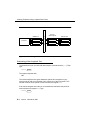
D
Isolating Problems Using Loopback Data Tests
D-1
■
■
■
■
■
■
Data Loopback Test
Local Loopback Test
Local Loopback Test with Self-Test
Remote Loopback Test
Remote Loopback Test with Self-Test
Loop-Around Data Test Arrangement
D-1
D-3
D-4
D-6
D-8
D-10
Issue 2 November 1996
v
Contents
E
Quick-Reference Summaries
E-1
GL
Glossary
GL-1
IN
Index
IN-1
vi
Issue 2 November 1996
About This Document
Purpose
The purpose of this guide is to provide information for installing, operating,
testing, and troubleshooting the 8400B Plus Data Module.
Organization of This Guide
The following paragraphs summarize the chapters and appendices contained in
this guide.
■
Chapter 1, “Introduction,” discusses the basic operating features of the
8400B Plus Data Module and describes the external indicators and
connectors.
■
Chapter 2, “Installation,” describes the hardware and software required
for installing the 8400B Plus Data Module, and outlines procedures for
preparing the 8400B Plus Data Module for operation.
■
Chapter 3, “Configuration and Operation,” describes how to issue
commands to your 8400B Plus Data Module. In addition, it describes
how to change, store, and recall configuration parameters, and outlines
how to create and save custom configuration profiles. It also provides
some basics on the operation of the 8400B Plus Data Module, outlines a
typical on-line data session, and discusses more advanced command
usage with example command lines. If you are not familiar with the AT
Issue 2 November 1996
vii
About This Document
command interface and you are not using your 8400B Plus Data Module
with a PC communications package, you will need to familiarize yourself
with this chapter.
■
Chapter 4, “Troubleshooting,” describes procedures for troubleshooting
problems that may be encountered while configuring and operating the
8400B Plus Data Module.
■
Appendix A, “AT Command Set,” contains an explanation of each AT
command accepted by the 8400B Plus Data Module.
■
Appendix B, “Dial Modifiers,” contains an explanation of each Dial
Modifier accepted by the 8400B Plus Data Module.
■
Appendix C, “S-Registers,” contains an explanation of each S-register
used by the 8400B Plus Data Module.
■
Appendix D, “Isolating Problems Using Loopback Data Tests,” provides
information on how to perform loopback tests and how to isolate
problems using the 8400B Plus Data Module.
■
Appendix E, “Quick-Reference Summaries,” contains quick-reference
summaries of AT commands, S-registers, result codes, factory-default
configuration settings, EIA/TIA-574 pin-outs, and the ASCII character
set.
A glossary and an index are provided at the rear of this guide.
viii
Issue 2 November 1996
How to Order Documentation
How to Order Documentation
This document’s order number is 555-020-709. To order this document:
Call:
Lucent Technologies Publications Center
Voice 1 800 457-1235
Fax 1 800 457-1764
International Voice 317 361-5353
International Fax 317 361-5355
OR
Write:
Lucent Technologies Publications Center
P.O. Box 4100
Crawfordsville, IN 47933
For more information about Lucent Technologies documents, see Business
Communications Systems Publications Catalog, 555-000-010.
How to Comment on This
Document
To comment on this document, please return the comment card at the back of
the document.
Issue 2 November 1996
ix
About This Document
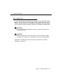
Conventions Used
Throughout this guide, command lines that are typed are shown in
typewriter-style characters, and responses that the 8400B Plus Data Module
returns are shown in italics. The following is an example.
AT H
ENTER
OK
Note the following characteristics of the display representation:
■
The first line is a command line as it should be typed. The ENTER symbol,
when shown, indicates that you must press the Enter or Return key to
complete the command line.
■
Spaces are used to separate commands in some examples shown in this
guide. In actual use, the spaces may be typed, but they are not required.
■
The second line in the example shows a typical response returned by the
8400B Plus Data Module.
Throughout this document, toll fraud security hazards are indicated by an
exclamation point inside a triangle and the words Security Alert.
! Security Alert:
Security Alert indicates the presence of a toll fraud security hazard. Toll
fraud is the unauthorized use of your telecommunications system by an
unauthorized party (for example, persons other than your company’s
employees, agents, subcontractors, or persons working on your
company’s behalf). Be sure to read “Your Responsibility for Your System’s
Security” on the inside front cover of this book and ‘‘Security Issues’’ on
page xi of this section.
x
Issue 2 November 1996
Security Issues
Security Issues
As a Lucent Technologies customer, you should be aware that there is an
increasing problem of telephone fraud. Telephone toll fraud can occur in many
forms, despite the numerous efforts of telephone companies and telephone
equipment manufacturers to control it. Some individuals use electronic devices
to prevent or falsify records of these calls. Others charge calls to someone
else’s number by illegally using lost or stolen calling cards, billing innocent
parties, clipping onto someone else’s line, or breaking into someone else’s
telephone equipment physically or electronically.
Today security problems are not just limited to toll fraud. There have been sharp
increases in reported incidents of hackers: criminals skilled in reprogramming
computer systems, accessing telecommunications systems through remote
administration or maintenance ports. These ports cannot be used to place
phone calls, but hackers can gain control over the setup of the system. Through
these ports, hackers create security “holes” to allow unauthorized calling — a
serious form of electronic vandalism.
Maintenance ports are their most recent target of abuse. In this scenario,
hackers find a private branch exchange (PBX) maintenance port number with
their “war dialer”; a device that randomly dials telephone numbers until a
modem or dial tone is obtained. They then “hack” the user ID and password,
sometimes just by using the PBX default passwords, to enter your system.
This is the most dangerous type of abuse because, once in your system, the
hackers have control over all the administrative commands. While in your
system, they have been known to:
■
Turn on Remote Access or Direct Inward System Access (DISA).
Hackers have been known to change the system at 8:00 p.m. to allow
fraudulent calls. Then, at 3:00 a.m., they reprogram the system back to
its original configuration. One company was hit three weekends in a row
before it realized what was happening.
■
Turn off Call Detail Recording (CDR) or Station Message Detail
Recording (SMDR), hack your system all weekend, then turn it back on
before Monday morning. This is especially disturbing to managers who
Issue 2 November 1996
xi
About This Document
are security conscious and check the CDR/SMDR reports every morning
looking for suspicious activity. They will not see records of the calls
because CDR/SMDR was turned off by the hackers. The administrator
may notice the absence of CDR/SMDR records for evening, night, and
weekend calls made by employees.
NETCON Data Channels
The NETCON (Network Control) data channels provide internal access to the
system management capabilities of your DEFINITY® Communications System.
If the 8400B Plus Data Module is connected to a modem, or there is a modem
pool, your system may be at risk for toll fraud.
Expert toll hackers will target the administration and maintenance capabilities of
your system. Once criminals gain access to the administration port, they are
able to change system features and parameters so that fraudulent calls can be
made. In a modem pool or NETCON modem installation, this would also permit
a hacker to transfer to a NETCON extension, get data tone, and obtain a login
prompt — permitting transfer out to make toll calls.
If the data module or modem must be connected to a NETCON administration
port, then deny access to any high-risk features or endpoints by placing them in
restriction groups on the DEFINITY Communications System. This restricts their
accessibility from the incoming facility or endpoints that could transfer a call.
Also, use Class of Restriction to Class of Restriction (COR-to-COR) to restrict
stations from calling the NETCON data channels, so that only CORs allowed to
access the maintenance port are able to do so. For example, if voice mail
extensions have a COR of 9, and extensions assigned to NETCON channels
have a COR of 2, ensure that COR 9 does not have access to COR 2. Anyone
not authorized to use the NETCON channel should not be able to access it.
In addition, a data module or modem port used for voice mail maintenance or
administrative access is often a switch extension. It should be restricted in the
same manner as the NETCON channel.
xii
Issue 2 November 1996
Security Issues
PBX Security Measures
Everyone in your company who uses the telephone system is responsible for
system security. Users and attendants need to be aware of how to recognize
and react to potential hacker activity. Informed people are more likely to
cooperate with security measures that often make the system less flexible and
more difficult to use.
Implement the following general security measures to protect your PBX, and
discourage the unauthorized use of your communications system.
■
Never program passwords or authorization codes onto auto-dial buttons.
Display phones reveal the programmed numbers, and internal abusers
can use the auto-dial buttons to originate unauthorized calls.
■
Discourage the practice of writing down passwords. If a password needs
to be written down, keep it in a secure place and never discard it while it
is active.
■
Attendants should tell their system manager if they answer a series of
calls where there is silence on the other end or the caller hangs up.
■
Users who are assigned voice mailboxes should frequently change
personal passwords and should not choose obvious passwords.
■
Advise users with special telephone privileges (such as Remote Access,
voice mail outcalling, and call forwarding off-switch) of the potential risks
and responsibilities.
■
Be suspicious of any caller who claims to be with the telephone company
and wants to check an outside line. Ask for a callback number, hang up,
and confirm the caller’s identity.
■
Never distribute the office telephone directory to anyone outside the
company; be careful when discarding it.
■
Never accept collect phone calls.
■
Never discuss your telephone system’s numbering plan with anyone
outside the company.
Issue 2 November 1996
xiii
About This Document
■
Change passwords frequently (at least quarterly). Set password
expiration times and tell users when the changes go into effect.
Changing passwords routinely on a specific date (such as the first of the
month) helps users to remember to do so.
■
Establish well-controlled procedures for resetting passwords.
■
Limit the number of invalid attempts to access a voice mail to five or less.
■
Monitor access to the dial-up maintenance port. Change the access
password regularly and issue it only to authorized personnel. Consider
using the Remote Port Security Device (RPSD) — a Lucent
Technologies product that helps protect your administration and
maintenance ports from unauthorized access.
■
Create a PBX system management policy concerning employee turnover
and include these actions:
— Delete all unused voice mailboxes in the voice mail system.
— If an employee is terminated, immediately delete any voice
mailboxes belonging to that employee.
— If a terminated employee had Remote Access calling privileges
and a personal authorization code, remove the authorization code
immediately.
— If barrier codes and/or authorization codes were shared by the
terminated employee, these should be changed immediately.
Notify the remaining users as well.
— If the terminated employee had access to the system
administration interface, their login ID should be removed (G3V3
or later). Any associated passwords should be changed
immediately.
xiv
■
Back up system files regularly to ensure a timely recovery should it be
required. Schedule regular, off-site backups.
■
Keep the attendant console and supporting documentation in an office
that is secured with a changeable combination lock. Provide the
combination only to those individuals having a real need to enter the
office.
Issue 2 November 1996
Lucent Technologies Fraud Intervention
■
Keep telephone wiring closets and equipment rooms locked.
■
Keep telephone logs and printed reports in locations that only authorized
personnel can enter.
■
Design distributed reports so they do not reveal password or trunk
access code information.
Lucent Technologies Fraud
Intervention
If you suspect you are being victimized by toll fraud and you need technical
support or assistance, call Technical Service Center Toll Fraud Intervention
Hotline at 1 800 643-2353.
Related Documentation
For additional information about securing against toll fraud, refer to the following
document:
Document #
Document Title
555-025-600
BCS Products Security Handbook
In addition, the following manuals may provide helpful information while
installing and using the 8400B Plus Data Module. Since each user may have
different equipment and software preferences or availability, only generic titles
are given for the manuals.
If you are using a terminal device other than a PC:
User’s guide for your terminal device. You may need information about
the configuration and capabilities of your terminal device from that
manual during the installation and preliminary operation of the 8400B
Plus Data Module.
Issue 2 November 1996
xv
About This Document
If you are using a PC as your terminal:
User’s guide for Microsoft® MS-DOS®. You may need this reference for
explanations of commands used by your PC to install, configure, and run
your PC communications package.
User’s guide for your PC communications package. You may need this
guide for information on how to configure your terminal emulation
software to access the 8400B Plus Data Module.
xvi
Issue 2 November 1996
Important Safety Instructions
Important Safety Instructions
When using your equipment, basic safety precautions, including the following,
should always be followed to reduce the risk of fire, electric shock, and injury to
persons:
■
Read and understand all instructions.
■
Follow all warnings and instructions marked on the product.
■
This product can be hazardous if immersed in water. To avoid the
possibility of electric shock, do not use when you are wet. If you
accidentally drop it into water, do not retrieve it until you have first
unplugged the power cord from the alternating current (AC) outlet, the
line cord from the modular wall jack, and all interconnecting cords from
the terminal equipment. Do not plug the cords back in until the product
has dried thoroughly.
■
Avoid touching the product during electrical storms in your immediate
area. There is a remote risk of electric shock from lightning. Even though
protective measures may have been installed to limit electrical surges
from entering your business, absolute protection from lightning is
impossible.
■
Never push objects of any kind through housing slots as they may touch
hazardous voltage points or short out parts that could result in a risk of
electrical shock. Never spill liquid of any kind on the product.
■
Disconnect the cords on this product before cleaning. Do not use liquid
cleaners or aerosol cleaners. Use a damp cloth for cleaning.
■
Slots and openings in the housing and the back or bottom are provided
for ventilation to protect it from overheating; these openings must not be
blocked or covered. The openings should never be blocked by placing
the product on a rug or other similar surface. This product should never
be placed near or over a radiator or heat register. This product should not
be placed in a built-in installation unless proper ventilation is provided.
■
This product should be operated only from the type of power unit
indicated in this manual. If you are not sure of the type of power supply
being used, contact a qualified service person.
Issue 2 November 1996
xvii
Important Safety Instructions
■
Do not allow anything to rest on the power cord. Do not locate this
product where the cord will be abused by persons walking on it.
■
Do not overload wall outlets and extension cords as this can result in the
risk of fire or electric shock.
■
Disconnect the cords on this product and refer servicing to qualified
service personnel under the following conditions:
a. When the power supply cord or plug is damaged or frayed.
b. If liquid has been spilled into the product.
c. If the product has been exposed to rain or water.
d. If the product does not operate normally by following the operating
instructions.
e. If the product has been dropped or the housing has been
damaged.
f. If the product exhibits a distinct change in performance.
!
SAVE THESE INSTRUCTIONS
When you see this symbol on the product, refer to the instruction booklet
packed with the product for more information before proceeding.
xviii
Issue 2 November 1996
Introduction
1
This chapter discusses the basic operating features of the 8400B Plus Data
Module and describes the external indicators and connectors.
The 8400B Plus Data Module is a new version of the 7400B Plus Data Module
and has been designed explicitly to work with two-wire DEFINITY Digital
Communications Protocol circuits. It is fully compatible with the 7400B Plus and
supports all of its functionality and applications.
Overview
Congratulations on the addition of the Lucent Technologies 8400B Plus Data
Module. Following our tradition of excellent quality and high reliability, we have
designed this new 8400B Plus Data Module with the latest advances in
telecommunications technology.
The 8400B Plus Data Module is a full-duplex asynchronous data module. It
provides integrated voice-data communications at the desktop over standard
twisted-pair wiring. At the desk, the 8400B Plus Data Module provides
asynchronous communication speeds ranging from 300 bps to 19.2 Kbps. The
8400B Plus Data Module’s ability to emulate a Hayes® compatible modem
interface makes it compatible with many standard PC communications
packages that use Hayes command sets. In addition, the 8400B Plus Data
Module provides a voice dial capability that allows you to initiate voice calls from
Issue 2 November 1996
1-1
Introduction
a personal computer (PC) using industry-standard ‘‘auto-dialer’’ PC
communications packages.
The 8400B Plus Data Module is a data service link between a Data Terminal
Equipment (DTE) device, a two-wire telephone, and a Lucent Technologies
DEFINITY® Communications System G3V2 or later.
NOTE:
Unless a specific DTE device is intended, the words terminal device shall
be used throughout this guide to represent any applicable DTE device,
including a dumb terminal, or a PC with an appropriate communications
package.
Features
A terminal device is connected to the 8400B Plus Data Module using a standard
Electronics Industries Association EIA-232-D Connector cord and, if needed,
the supplied M9/F25 Adapter. The M9/F25 Adapter converts a 25-pin interface
to a 9-pin interface, adhering to the Electronics Industries Association/
Telecommunications Industry Association EIA/TIA-574 standard. A Digital
Communications Protocol (DCP) interface (using a type D8W modular
telephone cord) is used to connect the 8400B Plus Data Module to the digital
PBX.
The 8400B Plus Data Module may be optioned for use either with or without a
telephone. In the stand-alone case, the 8400B Plus Data Module supports data
service only. Otherwise, the 8400B Plus Data Module provides simultaneous
data and voice service. The 8400B Plus Data Module works with all DCP voice
terminals that support two-wire operation (such as the 8400 series voice
terminals) to provide simultaneous data and voice service.
The voice dial feature allows you to dial a voice call without touching the
telephone. Depending on your communications package, you may also store
telephone numbers on a PC and recall them for dialing, log phone calls for easy
billing, and take notes for later reference during a telephone conversation.
1-2 Issue 2 November 1996
Physical Description
In addition, the 8400B Plus Data Module can be used to automatically turn on
the speakerphone of the voice terminal when a voice call is dialed from your
terminal device.
Additional features of the 8400B Plus Data Module include the following:
■
nonvolatile, read-write memory for storing installation options, two data
options profiles, and up to four telephone numbers
■
an AT command interface that emulates a Hayes 2400 Smartmodem™
and supports the following:
— storage of the wait time for carrier detect interval (S-register S7)
— voice call origination using the ATDP command
■
automatic speed and parity adjustment
■
even, odd, mark, space or no parity
■
automatic data throughput adjustment
■
power-up self-test
■
local and remote loopback tests with test duration timers
■
voice terminal powered by the PBX is not affected if AC power is
removed from the 8400B Plus Data Module
Physical Description
The 8400B Plus Data Module is housed in a black casing, approximately
5" x 7.75" x 1.5". Its name appears on the underside of the unit. The external
features of the front and rear panels and the separate power supply units are
described in this section.
Issue 2 November 1996
1-3
Introduction
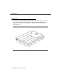
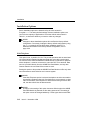
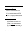
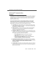
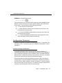
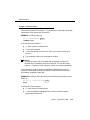
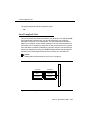
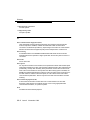
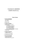
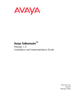
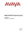
Front Panel
The front panel of the 8400B Plus Data Module is shown in Figure 1-1. One red
light emitting diode (LED) and one green LED on the front panel indicate the
status of the set during normal operation, and the result of self-tests when
initially powered.
Figure 1-1.
Front Panel of the 8400B Plus Data Module
1-4 Issue 2 November 1996
Physical Description
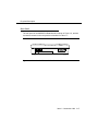
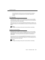
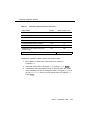
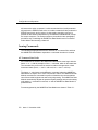
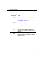
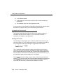
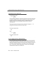
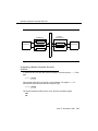
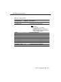
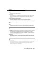
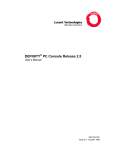
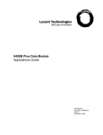
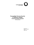
Rear Panel
The rear panel of the 8400B Plus Data Module is shown in Figure 1-2, and the
connectors located on the rear panel are described in Table 1-1.
PHONE
Figure 1-2.
LINE/
USE ONLY WITH COMMUNICATION
! POWER CIRCUIT POWER SOURCE
Rear Panel of the 8400B Plus Data Module
Issue 2 November 1996
1-5
Introduction
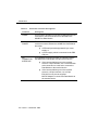
_
Table 1-1.
Rear Panel Connector Descriptions
Connector
Description
PHONE
This connector accepts one end of the D8W telephone line
cord used to connect a two-wire voice terminal to the
8400B Plus Data Module.
LINE/
POWER
This connector accepts one end of the D8W telephone
cord that connects between the 8400B Plus Data Module
and either:
EIA
CONNECTOR
INTERFACE
■
a PBX wall jack already powered by a closet
supply, or
■
a power supply, which is connected to the PBX
wall jack.
This unlabeled connector provides an interface between
the 8400B Plus Data Module and the terminal device.
■
If the communications port on the terminal
device is a 9-pin interface, use a cord with DB9
male connectors on each end to connect the
Data Module to the terminal device.
■
If the communications port on the terminal
device is a 25-pin interface, use a 25-pin
EIA-232-D cord, plus the supplied
M9/F25 Adapter to connect the Data Module to
the terminal device.
1-6 Issue 2 November 1996
Physical Description
Power Supply Unit
A Lucent Technologies power supply unit is shipped with each 8400B Plus Data
Module. This unit connects to a grounded AC outlet, and provides a connection
between the PBX wall jack and the 8400B Plus Data Module. The power supply
unit provides the necessary operating voltages for the 8400B Plus Data Module.
! CAUTION:
Use the 8400B Plus Data Module only with an approved communication
circuit power source.
! CAUTION:
Make certain that the AC outlet to which you connect the power supply is
unswitched (for example, not controlled by a wall switch or light dimmer).
Instructions for installing the power supply unit are provided in ‘‘Hardware
Installation’’ on page 2-8.
Issue 2 November 1996
1-7
Installation
2
This chapter describes the equipment required for installing the 8400B Plus
Data Module, and outlines procedures for preparing it for operation. If you are
using the 8400B Plus Data Module with a PC, you will be ready to use a PC
communications package after reading this chapter. If you are using the 8400B
Plus Data Module with a terminal, printer, or host, or you want to learn about the
AT interface and operations, read this chapter, and then continue to Chapter 3.
About the Terminal Device
The 8400B Plus Data Module operates with any asynchronous data terminal
device that has either an EIA-232-D or RS-232-C interface. If you are using a
PC as your terminal, you will need a suitable PC communications package. EIA
Connector cord and PC communications package requirements are described
in this chapter.
You must set the appropriate configuration options before connecting the 8400B
Plus Data Module to a printer or plotter. To do this, connect a data terminal or
PC to the EIA Connector Interface on the 8400B Plus Data Module, change and
store the necessary configuration parameters, remove the data terminal or PC,
and then connect the printer or plotter. The configuration parameters used for
this type of operation are described in ‘‘Remote Site Use’’ on page 3-13.
Issue 2 November 1996
2-1
Installation
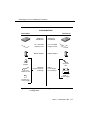
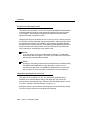
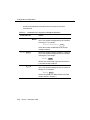
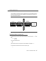
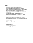
Selecting the Correct Installation
Procedure
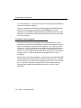
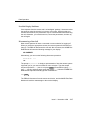
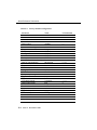
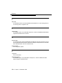
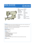
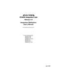
The 8400B Plus Data Module is available in two configurations. Before you can
successfully install the data module, you must ascertain which configuration you
have. Refer to Figure 2-1 (on page 2-3) for an illustration of the components
included with each configuration.
2-2
Issue 2 November 1996
Selecting the Correct Installation Procedure
CONFIGURATIONS
United States
International
8400B Plus
Data Module
8400B Plus
Data Module
one 7-foot D8W
telephone cord
two 7-foot D8W
telephone cords
M9/F25 Adapter
M9/F25 Adapter
400B2
Adapter
one power
cord
one 7-foot
D6AP 87 cord
DEFINITY
Adjunct Power Kit,
containing:
MSP-1
Power Supply
Kit, containing:
PHONE OTHER LINE
-7 +8 -2 +5
MSP-1
Power Supply
KS-22911,L2
Power Supply
Figure 2-1.
Components of the US Configuration and the International
Configuration
Issue 2 November 1996
2-3
Installation
What You Need
To install and operate the 8400B Plus Data Module, you will need the following
items:
■
an asynchronous data terminal or PC with a terminal emulation program
and EIA cord
■
(optional) a two-wire DCP voice terminal with D8W cord
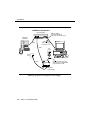
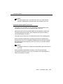
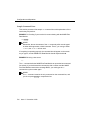
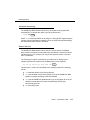
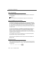
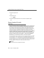
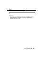
Figure 2-2 illustrates a standard US Configuration, using a telephone and
separate power supply.
Figure 2-3 illustrates a standard International Configuration, using a telephone
and separate power supply.
The US Configuration may be installed using the Lucent Technologies 1145A or
Lucent Technologies 1145B1 closet power supply. The International
Configuration may be installed using the Lucent Technologies 1145B1 closet
power supply. Both configurations are shown in Figure 2-4. This type of
installation eliminates the need for the separate power supply.
2-4
Issue 2 November 1996
Selecting the Correct Installation Procedure
8400B Plus Data Module
(Rear Endplate)
Telephone
(Optional)
PHONE!
M9/F25 Adapter
(use only with 25-pin
EIA-232-D Connector Cord)
USE ONLY WITH COMMUNICATION
LINE/
POWER CIRCUIT POWER SOURCE
D8W
EIA-232-D
(9-pin or 25-pin)
Connector Cord
D8W
AC
Outlet
KS-22911, L2
Power Supply
Wall
Jack
400B2
Adapter
D6AP
Figure 2-2.
Typical Installation of the US Configuration, including
Telephone and Separate Power Supply
Issue 2 November 1996
2-5
Installation
8400B Plus Data Module
(Rear Endplate)
PHONE!
Telephone
(Optional)
M9/F25 Adapter
(use only with 25-pin
EIA-232-D Connector Cord)
LINE/
USE ONLY WITH COMMUNICATION
POWER CIRCUIT POWER SOURCE
EIA-232-D
(9-pin or 25-pin)
Connector Cord
D8W
D8W
AC
Outlet
Wall
Jack
D8W
PHONE OTHER LINE
-7 +8 -2 +5
Actual connection may vary
according to the configuration
of your local AC outlet
MSP-1
Power Supply
Figure 2-3.
2-6
Typical Installation of the International Configuration,
including Telephone and Separate Power Supply
Issue 2 November 1996
Selecting the Correct Installation Procedure
8400B Plus Data Module
(Rear Endplate)
PHONE!
Telephone
(Optional)
LINE/
USE ONLY WITH COMMUNICATION
POWER CIRCUIT POWER SOURCE
M9/F25 Adapter
(use only with 25-pin
EIA-232-D Connector Cord)
D8W
D8W
EIA-232-D
(9-pin or
25-pin)
Connector
Cord
Wall
Jack
Figure 2-4.
Typical Installation of the US Configuration or International
Configuration, including Telephone and Closet Power Supply
Selecting an EIA Connector Cord
The standard EIA-232-D Connector cord (already supplied with your terminal or
PC) may be used with the M9/F25 Adapter, to connect your terminal or PC to
the 8400B Plus Data Module.
■
If the communications port on the terminal device is a 9-pin interface, use
a Connector cord with DB9 male connectors on each end to connect the
Data Module to the terminal device.
■
If the communications port on the terminal device is a 25-pin interface,
use a 25-pin EIA-232-D Connector cord, plus the supplied
M9/F25 Adapter to connect the Data Module to the terminal device.
Issue 2 November 1996
2-7
Installation
The most common EIA-232-D Connector cords are supplied with a male
connector at both ends. If you have this type of cord and the EIA-232-D port on
your terminal device is a male connector, you can use an adapter commonly
referred to as a “gender changer.” Otherwise, obtain an EIA Connector cord that
has the appropriate gender connector at each end to fit your application needs.
Selecting DCP Cords
One or more 7-foot D8W cords are supplied with your 8400B Plus Data Module.
Use the supplied cord, or obtain the appropriate length D8W telephone cord. If
you are using the With Telephone option (see ‘‘With Telephone’’ on page 2-12),
you will need the D8W telephone cord (already supplied with your telephone) to
connect between the 8400B Plus Data Module and your telephone.
Hardware Installation
This section outlines procedures for connecting the EIA Connector cord and
M9/F25 Adapter, installing the power supply, and connecting the D8W
telephone cord(s).
! CAUTION:
To avoid possible shock hazards and damage to the equipment, you
should perform the installation steps in the order given.
Connecting the 8400B Plus Data Module to the
Terminal
Use the EIA Connector cord and, if necessary, the M9/F25 Adapter to connect
the 8400B Plus Data Module to the terminal device.
1. Connect one end of the Connector cord into the communications port on
the terminal device. Tighten all retaining screws.
2-8
Issue 2 November 1996
Hardware Installation
2. If the Connector cord has 25 pins:
a. Plug the remaining end into the 25-pin portion of the
M9/F25 Adapter.
b. Plug the 9-pin portion of the M9/F25 Adapter into the EIA
Connector Interface on the rear panel of the 8400B Plus Data
Module. Tighten all retaining screws.
3. If the Connector cord has 9 pins, you do not need the M9/F25 Adapter:
a. Plug the remaining end into the EIA Connector Interface on the
rear panel of the 8400B Plus Data Module. Tighten all retaining
screws.
Connecting the 8400B Plus Data Module to the
PBX Wall Jack
Use the supplied DCP-type D8W telephone cord(s) to connect the 8400B Plus
Data Module to the PBX wall jack, and to the separate power supply if
necessary:
! CAUTION:
Make certain that the AC outlet to which you connect the power
supply is unswitched (for example, not controlled by a wall switch or
light dimmer).
NOTE:
Since the 8400B Plus Data Module does not have a power on/off
switch, the unit will power on as soon as the power supply is
connected to an active AC outlet.
1. Insert either end of the first D8W telephone cord into the connector
labeled LINE/POWER on the rear panel of the 8400B Plus Data Module.
Issue 2 November 1996
2-9
Installation
2. If you are installing the US Configuration, and using the separate power
supply provided with your 8400B Plus Data Module:
a. Plug the 400B2 Adapter into the PBX wall jack.
b. Plug the remaining end of the first D8W telephone cord into the
bottom connector on the 400B2 Adapter.
c. Plug one end of the D6AP cord into the power supply unit.
d. Plug the other end of the D6AP cord into the top connector on the
400B2 Adapter.
e. Plug the power supply unit into a 120 VAC, 60 Hz outlet.
3. If you are installing the International Configuration, and using the
separate power supply provided with your 8400B Plus Data Module:
a. Insert the remaining end of the first D8W telephone cord into the
connector labeled PHONE on the power supply.
b. Insert one end of the second D8W cord into the connector labeled
LINE on the power supply.
c. Insert the remaining end of the second D8W cord into the PBX
wall jack.
d. Plug the power supply cord into the power supply unit.
e. Plug the other end of the power supply cord into an appropriate
AC outlet. If the power supply cord provided with the MSP-1
Power Supply is not compatible with your AC outlet, you may
either:
1. use an adapter to conform to local blade arrangement, or
2. use a replacement cord if an appropriate adapter is not
available.
4. If you are using a closet power supply instead of the separate power
supply, insert the remaining end of the first D8W telephone cord into the
PBX wall jack.
2-10
Issue 2 November 1996
Initial System Checks
Connecting a Telephone
If you are using the With Telephone option of the 8400B Plus Data Module
(voice and data), install the telephone and any connected adjunct equipment as
follows:
1. Insert either end of the remaining D8W telephone cord into the line jack
on your two-wire telephone.
2. Insert the other end of the telephone cord into the jack labeled PHONE
on the rear panel of the 8400B Plus Data Module.
NOTE:
See ‘‘Installation Options’’ on page 2-12 for instructions to select
the With Telephone installation option.
NOTE:
If your voice terminal has data capabilities, those data features are
not supported while the voice terminal is connected to the 8400B
Plus Data Module.
Initial System Checks
The following sections describe procedures for initially checking out your
hardware and any required software. It is assumed at this point that your PC
communications package has been properly installed and is ready for use. (See
‘‘Selecting PC Communications Packages’’ on page 2-21 for guidelines when
selecting your PC communications package.)
NOTE:
PC communications software is required only if you are using a PC as
your terminal device. A dedicated data terminal does not need PC
communications software.
Issue 2 November 1996
2-11
Installation
Installation Options
Seven installation options are determined by the value entered in
S-register S24. The factory-default settings of these installation options are
correct for the majority of applications. Check the default values, listed in
Table 2-1, to determine whether you need to make any changes.
NOTE:
Changes to these installation options will not affect the factory-default
configuration. Conversely, loading the factory default configuration (using
the AT&F command) will not affect these installation options. For
additional information on the factory-default configuration, refer to
page A-24.
With Telephone
This option is set, by default, for Yes. This permits operation with an associated
voice terminal and enables simultaneous data and voice calls over the same
line from the PBX. When the 8400B Plus Data Module is optioned for operation
with a telephone, it must be connected to a two-wire DCP voice terminal. Data
service is provided directly from the 8400B Plus Data Module, and any data
features that the voice terminal offers cannot be used.
Setting this option to No permits the 8400B Plus Data Module to offer only data
service between a terminal device and a remote system.
NOTE:
If the With Telephone option is selected a telephone must be connected to
successfully complete a data call. If a telephone is not connected, no data
calls can be made. If the telephone is disconnected during an active data
call, the data call will also be disconnected.
NOTE:
A change in the setting of this option becomes effective when the 8400B
Plus Data Module is powered on after being powered off. The setting of
this option cannot be changed arbitrarily. It must agree with how the PBX
2-12
Issue 2 November 1996
Installation Options
line is administered. Check with your telecommunications manager to
administer the line for simultaneous voice and data or data service
required.
US Companding
This option is set, by default, for Yes. Leaving this default permits the 8400B
Plus Data Module to digitize voice signals according to the Mu-Law standards
commonly used within the United States.
Setting this option to No requires the 8400B Plus Data Module to digitize voice
signals according to the A-Law standards commonly used outside of the United
States.
NOTE:
A change in the setting of this option becomes effective immediately.
Telephone Provides Dialing
This option is set, by default, for Yes. Leaving this default permits the 8400B
Plus Data Module to use the telephone’s DTMF dialing circuits to perform the
dialing function. This setting also permits the telephone to annunciate the
touch-tones.
Setting this option to No requires the 8400B Plus Data Module to perform the
dialing function using its internal DTMF dialing circuit. The No setting does not
allow touch-tones to be annunciated.
NOTE:
A change in the setting of this option becomes effective immediately.
Issue 2 November 1996
2-13
Installation
Disable Data Metering Feature
This option is set, by default, for Yes. This requires the 8400B Plus Data Module
to adjust its transfer speed to match the transfer speed of the remote system.
The CONNECT xxxx message is displayed to indicate the transfer speed
selected when the connection is made.
Changing this option to No allows the user to set up a call to a remote end that
is running at a slower speed than the local data module, without having to lower
the speed of the terminal. The CONNECT xxxx message will always indicate
the speed of the local data transfer. The 8400B Plus Data Module performs the
speed conversion and uses the Clear to Send (CTS) lead to flow-control the
user’s terminal if it is sending too much data too fast.
NOTE:
If you are using a PC with a communications package, or a dedicated
terminal that does not support CTS control, you cannot make file transfers
with the data metering feature enabled.
NOTE:
A change in the setting of this option becomes effective immediately when
the 8400B Plus Data Module is in the idle mode or as soon as it is
returned to the idle mode. The 8400B Plus Data Module is in idle mode
any time that it is not in test mode or connected to an active data call.
Immediate Speakerphone Activation
This option is set, by default, for Yes. This permits the speakerphone (if
available) to be activated before dialing, and allows the user to hear the
dial-tone and touch-tones when the Telephone Provides Dialing option is set to
Yes. (See ‘‘Telephone Provides Dialing’’ on page 2-13.)
Setting this option to No causes the speakerphone to be activated after dialing.
The user can still hear the far-end ringing and answering.
2-14
Issue 2 November 1996
Installation Options
NOTE:
This option applies only to voice-dial calls, and is only valid when the
Automatic Speakerphone Activation option (see below) is set to Yes.
Automatic Speakerphone Activation
This option is set, by default, for Yes, permitting automatic activation of the
speakerphone when you use your terminal to dial a voice call.
Setting this option to No causes the 8400B Plus Data Module to disable the
automatic speakerphone feature, and necessitate the use of a handset or
manual speakerphone activation.
This option has no effect if the voice terminal does not have a speakerphone.
When Immediate Speakerphone Activation and Automatic Speakerphone
Activation are set to Yes, the 8400B Plus Data Module automatically activates
the speakerphone at the beginning of the voice call so you can hear dial-tone
and touch-tones.
NOTE:
To enable this feature, the Telephone Provides Dialing option must also be
set to Yes.
When Immediate Speakerphone Activation is set to No and Automatic
Speakerphone Activation is set to Yes, the activation of the speakerphone is
delayed until dialing is complete.
Issue 2 November 1996
2-15
Installation
Disable Busyout Feature During Local
Loopback Test
This option is set, by default, for Yes. The 8400B Plus Data Module will not
busyout the DCP line while performing a Local Loopback Test or Local
Loopback Self-Test.
Changing this option to No allows the 8400B Plus Data Module to busyout the
DCP line when either the Local Loopback or Local Loopback Self-Test mode is
entered. This will cause a busy signal when the set is called. The busyout
condition is released when the test ends.
NOTE:
A change in the setting of this option becomes effective immediately when
the 8400B Plus Data Module is in the idle mode or as soon as it is
returned to the idle mode. The 8400B Plus Data Module is in idle mode
any time that it is not in a test mode or connected to an active data call.
Changing Installation Options
All seven installation options are set in S-register S24 via a number that
represents their collective value.
2-16
■
To accept the default value of Yes for all options, leave the value of 0
(zero) in S-register S24.
■
To specify No for only one of the options, enter its value (see Table 2-1)
in S-register S24. For example, to change Automatic Speakerphone
Activation to No, enter 64 in S-register S24.
■
To specify No for two or more options, add together the value for each of
those options (see Table 2-1), and enter the total in S-register S24. For
example, to set With Telephone to No and Disable Data Metering
Feature to No, enter 17 in S-register S24.
Issue 2 November 1996
Changing Installation Options
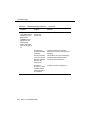
Table 2-1.
Installation Option Defaults and Values
Option Name
Default
Value To Select “No”
With Telephone
Yes
1
US Companding
Yes
2
Telephone Provides Dialing
Yes
4
Disable Data Metering Feature
Yes
16
Immediate Speakerphone Activation
Yes
32
Automatic Speakerphone Activation
Yes
64
Disable Busyout Feature During Local
Loopback Test
Yes
128
Total, and enter value in S24
➜
To adjust the installation options, perform the following steps.
1. Using Table 2-1, determine the total value to be entered in
S-register S24.
2. Check the current value of S-register S24 by typing ATS24?
ENTER
.
3. If the desired value (ascertained in Step 1) does not match the current
value (ascertained in Step 2), change the value of S-register S24. To do
so, type ATS24=xxx, where xxx is the desired value of S-register S24.
Press ENTER .
Issue 2 November 1996
2-17
Installation
LED Indications
Two LEDs are located on the top of the 8400B Plus Data Module. One LED is
red, and the other LED is green. These indicate the status of the set during
normal operation, and the result of self-tests when the unit is initially powered.
When power is first applied to the 8400B Plus Data Module, the unit performs a
self-test to verify that it is in working order. During the self-test, both LEDs will
remain lit. When the self-test is complete, the green LED will turn off.
■
If self-test passed, the red LED will remain on. This indicates that your
8400B Plus Data Module is installed and READY for data
communications operation.
■
If self-test failed, the red LED will flash three times, and then remain on.
This indicates a defective unit. Call the Lucent Technologies Technical
Service Center at 1 800 242-2121.
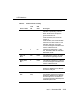
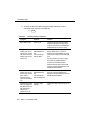
Table 2-2 lists all possible LED indications. Also refer to Chapter 4 for
troubleshooting guidelines.
2-18
Issue 2 November 1996
LED Indications
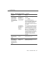
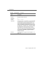
Table 2-2.
LED Indication Summary
Status of Unit
Green
LED
Red
LED
Self-Test
On
On
Description
When the unit is first powered, this
indicates it is performing a self-test.
When the self-test is complete, the
green LED will turn off.
If self-test passed, the red LED will
remain on.
If self-test failed, the red LED will flash
three times, and then remain on. This
indicates a defective unit. Call the
Lucent Technologies Technical Service
Center at 1 800 242-2121.
Idle
On
On
Following the initial power-up of the
unit, this indicates that the 8400B Plus
Data Module is idle.
Other Test
Modes
Flash*
Flash*
This indicates the unit is in test mode.
For information regarding test mode,
refer to Appendix D.
Memory Error
Mode
Off
Flash*
This indicates a defective unit. Call the
Lucent Technologies Technical Service
Center at 1 800 242-2121.
Switch Link
Down
Wink†
Inverted
Wink ‡
The unit is unable to communicate with
the PBX. Restore the connection
between the 8400B Plus Data Module
and the PBX wall jack.
Phone Link
Down
Inverted
Wink‡
Wink†
The unit is unable to communicate with
the telephone. Restore the connection
between the 8400B Plus Data Module
and the telephone. If no telephone is
connected, change the With Telephone
installation option to No.
Issue 2 November 1996
2-19
Installation
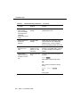
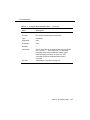
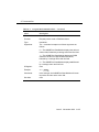
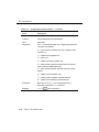
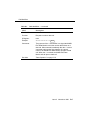
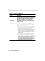
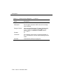
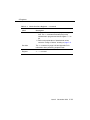
Table 2-2.
LED Indication Summary — Continued
Status of Unit
Green
LED
Red
LED
Idle
Off
On
Description
This is the unit’s normal mode if no
active data call exists.
The transmission of a character on the
Send Data lead will cause the red LED
to flash OFF for 100 ms.
The transmission of a character on the
Receive Data lead will cause the green
LED to flash ON for 100 ms.
The transmission of a continuous
stream of characters, on the Send Data
or Receive Data leads, will cause its
LED to flash OFF and ON at 100 ms
intervals.
Incoming Call
Flash*
On
Active Data Call
On
On
This indicates an incoming call.
This indicates an active data call.
The transmission of a character on the
Send Data lead will cause the red LED
to flash OFF for 100 ms.
The transmission of a character on the
Receive Data lead will cause the green
LED to flash OFF for 100 ms.
The transmission of a continuous
stream of characters, on the Send Data
or Receive Data leads, will cause its
LED to flash OFF and ON at 100 ms
intervals.
*
†
‡
2-20
A Flash is a repeating pattern of 500 ms ON and 500 ms OFF.
A Wink is a repeating pattern of 750 ms ON and 250 ms OFF.
An Inverted Wink is a repeating pattern of 250 ms ON and 750 ms OFF.
Issue 2 November 1996
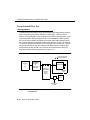
Selecting PC Communications Packages
Selecting PC Communications
Packages
The purpose of PC communications software is to allow your PC to operate as
an asynchronous voice-data communications terminal. Of the many software
packages available, all perform essentially the same functions, but often in
significantly different ways.
If you do not already have a PC communications package, consult with an
experienced user for advice on selecting software to suit your voice-data
communications needs. The following, though not required, are a few helpful
features that you may wish to look for in the software you select:
■
Local mode. Also called terminal mode, dumb terminal mode, or chat
mode, this feature allows you to issue AT commands to the 8400B Plus
Data Module to configure its options.
■
Dialing directory. This feature allows you to store several frequently
called numbers, often along with configuration of the data options
needed for completing the connection.
■
Auto-dialer software. This feature allows you to automate the process
of dialing a voice call without touching the telephone. The following three
basic types of auto-dialer software are available:
— Phone Management supports call log and note taking
— DOS Utilities typically supports auto-dial capabilities
— Personal Information Managers (PIM) supports automated
calendars, databases, time lines, and pert charts
■
Predefined data option profiles. Some programs include completely
defined data option profiles (also called configuration profiles) for popular
modems. If available, select the option profile for the Hayes
Smartmodem 2400.
■
Command files. These files, also called script files, allow you to define a
group of commands that may be executed for automatically logging into
specific remote devices.
Issue 2 November 1996
2-21
Installation
If You Are Using a PC
PC communications packages provide the capability of configuring the 8400B
Plus Data Module automatically. When using a PC communications package
with the 8400B Plus Data Module, there are two items to note:
1. The PC communications package should be configured to work with a
Hayes Smartmodem 2400 or Hayes compatible modem.
2. The dialing method of the PC communications package should be set to
Tone for data calls and Pulse for voice calls.
Many PC communications packages provide the possibility of writing script or
command files. These files can then be run to execute a sequence of
commands that will configure your system, or even provide an automatic log-on
procedure for a particular remote end device. Review the documentation for
your PC and PC communications package. Once you understand the PC
communications package well enough, you will be ready to begin using it with
the 8400B Plus Data Module.
Since there is such a diversity of functionality among the many PC
communications packages available, refer to the user’s manual of the package
for specific details about its use.
For more information about the AT interface and operation of the 8400B Plus
Data Module, refer to Chapter 3.
If You Are Using a Dedicated Terminal
When a dedicated terminal is used with an 8400B Plus Data Module, you must
control the operation of the 8400B Plus Data Module. In a way, you are acting
as a PC communication package. To do this, you must understand the
operation of the 8400B Plus Data Module. Refer to Chapter 3 for information on
the configuration and operation of your 8400B Plus Data Module.
2-22
Issue 2 November 1996
Configuration and Operation
3
This chapter describes how to change, store, and recall configuration
parameters; outlines how to create and save custom configuration profiles; and
discusses more advanced command usage with example command lines.
This chapter also provides some basics on the operation of the 8400B Plus
Data Module, describes how to use a few AT commands that are essential for
most voice-data communications operations, and then outlines a typical on-line
session.
NOTE:
The commands for the 8400B Plus Data Module are referred to as AT
commands because you must type the letters AT as the first characters on
the line for most commands.
Operating Modes
Except when a test condition has been initiated, the 8400B Plus Data Module is
always in one of two states: command mode or data mode. When power is first
applied, the 8400B Plus Data Module initializes to command mode after
self-test is complete.
In command mode, the 8400B Plus Data Module looks at everything you type
on your keyboard. When you type in something that the 8400B Plus Data
Module recognizes as a valid command with a valid parameter (if required), it
Issue 2 November 1996
3-1
Configuration and Operation
will execute the action requested. A valid command with an invalid parameter
will produce the ERROR result code. An invalid command will also produce the
ERROR result code, and is ignored. In data mode, everything you type is
passed as data without interpretation by the 8400B Plus Data Module, except
the escape sequence. The escape sequence, described in later paragraphs,
provides a way of switching the 8400B Plus Data Module back to command
mode without disconnecting a data call.
Issuing Commands
The following paragraphs describe the elements of a command line and how
the 8400B Plus Data Module responds to a command line when it is issued.
AT Command Line Prefix
All command lines issued to the 8400B Plus Data Module must begin with the
letters AT or at with the exception of the A/ command, which is discussed later.
The command line prefix must be entered as either both uppercase or both
lowercase letters (that is, at and AT will work, but aT and At will not).
The letters AT, also known as the ATtention command, alerts the 8400B Plus
Data Module to expect one or more commands to follow. The 8400B Plus Data
Module examines the command line prefix to determine the communications
rate of the terminal equipment as well as its parity setting. The 8400B Plus Data
Module automatically adjusts the speed and parity settings and uses the setting
until another AT command is received, or until the 8400B Plus Data Module is
powered down.
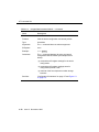
Formats supported by the 8400B Plus Data Module are shown in Table 3-1.
3-2
Issue 2 November 1996
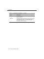
Issuing Commands
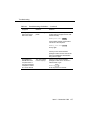
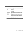
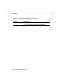
Table 3-1.
Character Formats
Data Bits
Parity
Stop Bits
7
even or odd
1
7
mark or space
1
8
none
1
All of these parameters may be changed on the local terminal device as
needed. The 8400B Plus Data Module will adjust to match the speed and parity
of the local terminal device when it receives an AT command.
If you connect to a remote system and your screen shows a series of nonsense
characters (also referred to as “garbage”), chances are that you need to adjust
the speed or parity on the terminal to match the settings of the 8400B Plus Data
Module, which has adjusted its speed to match the remote system.
Command Buffer
As you type in a command, each character is saved in a 40-character buffer.
The AT prefix, spaces, and the ENTER at the end of the command line are not
saved and do not add to the character count. If you try to type more than 40
countable characters on one line, the result code ERROR will be displayed on
your terminal screen, and the command line will be ignored.
Command Line Set Up
A command line begins with the AT prefix, includes one or more commands,
and finishes with a line termination character, usually issued by pressing the
ENTER key. The factory-default line termination character is an ASCII carriage
return.
If you make an error while typing a command line, you can send the backspace
character, usually issued by pressing the BACKSPACE key, as often as needed to
delete the error. However, as soon as you enter the AT prefix, the 8400B Plus
Data Module immediately reads it and sets up for a command to follow. Hence,
Issue 2 November 1996
3-3
Configuration and Operation
you cannot delete the AT prefix once it is typed. The factory-default backspace
character is an ASCII backspace.
Once you complete a command line by pressing ENTER , the 8400B Plus Data
Module will try to interpret all characters on the command line as valid
commands. If the 8400B Plus Data Module finds a character that is not a valid
command, it will ignore the erroneous character and any remaining characters
on the command line.
Command Acknowledgment
Commands are acted upon immediately and are acknowledged by a result
code. Most commands are acknowledged by OK. This assumes that the result
codes are configured in the verbose form (command V1 is in effect), and are
enabled (Q0 in effect). Another option for configuring result codes is the short or
numeric form. These result codes are set by the V0 command, which would
produce a 0 (zero) instead of the message OK. A final option for result codes is
to disable them (Q1). Refer to Appendix A for descriptions of the V and Q
commands.
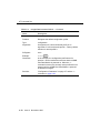
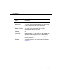
Several other result codes may appear on your terminal screen while the 8400B
Plus Data Module is completing a call. The option selected by the X command
controls which of these result codes may appear on the screen of your terminal
(the X command is described in Appendix A). All result codes that may be
returned by the 8400B Plus Data Module are shown in Table 3-2 and in
Appendix E.
3-4
Issue 2 November 1996
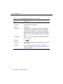
Issuing Commands
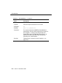
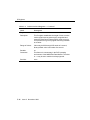
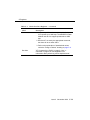
Table 3-2.
Result Codes
Verbose Form
Numeric
Description
OK
0
Command accepted
CONNECT
1
Connection made at 300 bps
NOTE:
If command X0 is in effect,
CONNECT means connection
made at whatever speed both
ends of the call agreed upon.
RING
2
Ring signal detected
NO CARRIER
3
Carrier signal not detected or lost
ERROR
4
Error in command line
CONNECT 1200
5
Connection made at 1200 bps
BUSY
7
Busy signal detected
CONNECT 2400
10
Connection made at 2400 bps
CONNECT 4800
11
Connection made at 4800 bps
CONNECT 9600
12
Connection made at 9600 bps
CONNECT 19200
14
Connection made at 19200 bps
Repeating a Command
As mentioned earlier, the command buffer contains the last completed
command line. If you wish to repeat the previous command line without retyping
it, type A/ without the AT command prefix and without pressing ENTER . This
command is most useful when you have typed a command line to have the
8400B Plus Data Module dial a number, and it returns the result code BUSY.
Use the A/ command to redial the number as often as you wish.
Issue 2 November 1996
3-5
Configuration and Operation
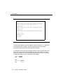
Sample Command Lines
This section presents a few sample AT command lines with explanations of the
results they will produce.
EXAMPLE 1: Checking if your terminal is communicating with the 8400B Plus
Data Module.
AT
ENTER
NOTE:
Remember, the two characters of the AT command prefix must be typed
as either both uppercase or both lowercase. That is, you can type either
at or AT, but At or aT will not work.
If everything is operating properly, the command should appear on the screen
as you type it, and the 8400B Plus Data Module should respond with OK.
EXAMPLE 2: Using a time saver.
A/
The A/ command tells the 8400B Plus Data Module to repeat the last command
line exactly. If you had issued the command to dial a number and the 8400B
Plus Data Module returned the message BUSY, you could type the A/
command to try the number again.
NOTE:
The A/ command must be the only command on the command line, and
you do not press ENTER to complete the line.
3-6
Issue 2 November 1996
Configuration Parameters
EXAMPLE 3: Changing data options.
AT E1 &D2 S0=5
ENTER
This command line is a command sequence that sets up the 8400B Plus Data
Module to set the command echo option, the DTR option, and the automatic
answer option. The commands set the following parameters:
■
AT is the required command prefix.
■
E1 causes characters entered from the keyboard to be echoed to the
screen while in command mode.
■
&D2 causes the 8400B Plus Data Module to hang up the call when the
local terminal turns off DTR.
■
S0=5 causes the 8400B Plus Data Module to enter automatic answer
mode and answer incoming calls on the fifth ring.
Configuration Parameters
Values for configuration parameters are selected by using AT commands. For a
description of all AT commands used by the 8400B Plus Data Module, refer to
Appendix A.
Parameter Storage and Retrieval
Configuration parameter values include the option values selected by AT
commands that require option values and the values stored in the S-registers. A
set of configuration parameter values is called a profile. The 8400B Plus Data
Module has four configuration profiles at any given time: one active, two stored,
and one that permanently contains the factory-default values.
Unsaved changes to configuration parameters remain in effect until they are
changed again, or until the 8400B Plus Data Module is disconnected from the
AC power source. Before making or storing any changes, or checking changes
that you have made, you can issue an AT command to view the values that are
currently in the active profile and the two stored profiles.
Issue 2 November 1996
3-7
Configuration and Operation
The active profile contains the parameter values that are currently in effect. All
parameter values can be changed, and most changes can be stored to one of
the two profile storage locations by issuing an AT command. Another AT
command recalls values from one of the two stored profiles into the active
profile.
Factory-default parameter values are a selection of values that are appropriate
for a wide number of applications. These values are stored permanently in
read-only memory (ROM) and you can issue an AT command to recall them into
the active profile at any time.
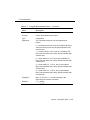
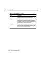
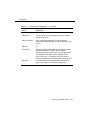
Commands to view, store, and recall configuration parameters are summarized
in Table 3-3. The commands discussed in this section are described in greater
detail in Appendix A. To determine whether a configuration parameter that
affects a particular S-register can be stored in memory, refer to Appendix C.
3-8
Issue 2 November 1996
Configuration Parameters
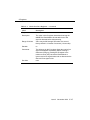
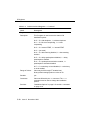
Table 3-3.
Commands to Store, Recall, and View
Configuration Parameters
Command Line:
Action:
AT&V
Display current AT command settings and S-register
values in the active profile and the two stored profiles
(also displays the four stored telephone numbers,
which are described in the section titled ‘‘Storing a
Telephone Number’’ on page 3-11).
ENTER
AT&Wn
ATZn
ENTER
AT&Yn
AT&F
ENTER
ENTER
ENTER
Store the configuration parameters in the active profile
to one of the two storage locations, where n represents
the desired location and may be 0 or 1.
Immediately reset the 8400B Plus Data Module and
recall one of the two stored configuration profiles into
active status, where n represents the desired profile
and may be 0 or 1.
Recall one of the two stored configuration profiles into
active status when the 8400B Plus Data Module is
powered on, where n represents the desired profile and
may be 0 or 1.
Recall the factory-default configuration settings into the
active profile. Note that this command does not load the
Installation Option factory default values into the active
profile (S-register S24).
Issue 2 November 1996
3-9
Configuration and Operation
Data Operation
This section provides information on how to use the 8400B Plus Data Module
for data calls.
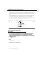
From Data Mode to Command Mode and Back
An escape sequence, +++ , can be typed at any time during a data call to return
temporarily to command mode. Your call does not disconnect, but data is not
exchanged. Once you have “escaped” to command mode, the 8400B Plus Data
Module returns OK to acknowledge that it has entered command mode (see
‘‘Command Acknowledgment’’ on page 3-4).
At this point, you can issue commands to the 8400B Plus Data Module. As long
as the data call has not been disconnected, you can use the ATO command to
return to data mode.
One other condition will cause the 8400B Plus Data Module to switch from data
mode to command mode. If the PBX senses that the remote device has
disconnected, it will disconnect the call to the 8400B Plus Data Module. The
8400B Plus Data Module will turn off the green LED, turn on the red LED if it is
not already on, display a result code message on your terminal screen (such as
NO CARRIER), and then return to command mode.
The escape sequence and all other commands discussed in this section are
explained in Appendix A.
Dialing a Data Call
The dial command is issued to the 8400B Plus Data Module in the form
ATDTnnn...n, where D is the dial command, T is the dial modifier (see
Appendix B for more information on dial modifiers), and nnn...n represents
the number you wish to dial. The command line can hold up to 40 characters, so
you can usually precede the D with other commands on the same line.
3-10
Issue 2 November 1996
Data Operation
The following is an example:
ATDT74768
ENTER
In the example, the command will cause the 8400B Plus Data Module to go off
hook, dial the number, and then wait the period of time specified in S-register S7
for the call to be completed.
If the call cannot be completed, the 8400B Plus Data Module may disconnect
and send the result code NO CARRIER or BUSY to your display screen. When a
call is successfully completed, the 8400B Plus Data Module will send the result
code CONNECT nnnn to your screen, where nnnn represents the speed of the
8400B Plus Data Module (for example, 1200).
NOTE:
The speed sent in the CONNECT xxxx message may not be the same
speed used to dial the call. In this case, the terminal speed must be
changed to match the new speed.
Storing a Telephone Number
The 8400B Plus Data Module is capable of storing up to four telephone
numbers, each of which can contain up to 25 characters. Numbers stored in this
way remain available indefinitely, even after the 8400B Plus Data Module has
been powered off and then on again.
Table 3-4 describes the command lines used to store a telephone number,
delete a number from storage, and dial a stored number.
NOTE:
Digits 0 through 9 and all letters a through z and A through Z may be part
of the stored “number.” Spaces and hyphens (-) may be used in the
number when typing the command line. Spaces are not stored and do not
add to the total count of characters in the stored number, but all other
ASCII characters are stored and counted. Any ASCII character may be
used, as long as it is acceptable to the PBX. A semicolon (;) character
cannot be stored because it is used to delimit the end of the string being
Issue 2 November 1996
3-11
Configuration and Operation
stored so that additional commands can be entered on the same
command line.
Table 3-4.
Commands for Using Stored Telephone Numbers
Command Line:
AT&Zm=nnn...n
Action:
ENTER
Store number nnn...n in location m, which is
one of four locations designated by the numbers
0 through 3. For example:
AT&Z2=918006245123
ENTER
stores the number 918006245123 in number
storage location 2.
AT&Zm=
ENTER
Delete any number stored in location m, which is
one of four locations designated by the numbers
0 through 3. For example:
AT&Z2=
ENTER
deletes any number that may have been stored
in number storage location 2.
ATDS=m
ENTER
Dial the number stored in location m, which is
one of four locations designed by the numbers 0
through 3. For example:
ATDS=2
ENTER
causes the 8400B Plus Data Module to dial the
number stored in location 2.
3-12
Issue 2 November 1996
Data Operation
Automatic Answering
The 8400B Plus Data Module can be set up to answer incoming data calls
automatically. To initialize this option, type the command line:
ATS0=nnn
ENTER
where nnn is a decimal number in the range of 1 through 255, representing the
number of rings to wait before answering. If nnn is 0 (the factory-default setting),
the automatic answer feature is turned off.
Remote Site Use
The 8400B Plus Data Module can be used at a remote site as a dedicated
service device to answer incoming data calls, send data to a remote end device,
and then hang up. For example, you may wish to provide access to a printer
from a remote site.
The following is a typical command line you might use for setting up this
operation (spaces are used here for readability, but are not required):
AT &F &C1 &D2 E0 Q1 S0=1 &W0 &Y0
ENTER
Following the AT prefix, the commands in the example produce the following
results:
■
&F resets the options to the factory defaults.
■
&C1 sets the Data Carrier Detect (DCD) circuit of the 8400B Plus Data
Module to operate according to the EIA standard.
■
&D2 sets the 8400B Plus Data Module to go on hook when an on-to-off
transition is detected on the Data Terminal Ready (DTR) input,
disconnecting the call.
■
E0 turns off the echo.
Issue 2 November 1996
3-13
Configuration and Operation
■
Q1 turns off the result codes that would be the normal responses of the
8400B Plus Data Module to commands that it receives. (For example,
the CONNECT message that is displayed when answering a call would
interfere with the printer.)
■
S0=1 turns on the automatic answer feature and causes the 8400B Plus
Data Module to answer an incoming data call on the first ring.
■
&W0 causes the current configuration to be stored in data profile storage
location 0.
■
&Y0 selects the configuration stored in data profile storage location 0 to
become the current configuration each time the 8400B Plus Data Module
is powered on.
Refer to Appendix A for a complete description of each command used in this
section.
Reset and Configuration Recall
Two commands are available for recovering from various data communications
problems. You can reset the 8400B Plus Data Module and recall one of two
stored profiles as the current configuration. The form for this command is as
follows:
ATZn
ENTER
where n is the number 0 or 1, representing the configuration profile to be
recalled.
A second command allows you to recall the factory-default configuration if, for
instance, you lose track of the active configuration changes you have made and
need to start over. The form for this command is as follows:
AT&F
3-14
ENTER
Issue 2 November 1996
Data Operation
Sample Command Lines
This section presents a few sample AT command lines for data calls, along with
explanations of the results they will produce.
EXAMPLE 1: Dialing a data call.
AT D T 18006245123
CONNECT 2400
ENTER
In the first line of this example:
■
AT is the required command prefix.
■
D is the dial command.
■
T is the dial modifier for a data call. (This is not required, and may be
omitted.)
■
The remainder of the line is the telephone number.
NOTE:
The spaces between the commands and the telephone number are
included only for readability and are not required. You may also insert
hyphens (-) anywhere in the telephone number for increased readability.
In the second line of this example, the 8400B Plus Data Module returns a
response indicating that a connection with the remote end device has been
successfully completed at 2400 bps.
EXAMPLE 2: Dialing a data call outside your PBX domain with another option
thrown in.
AT &F D 9 1 800 555-5555
BUSY
ENTER
In the first line of this example:
■
AT is the required command prefix.
■
&F tells the 8400B Plus Data Module to restore the factory-default
configuration parameters.
Issue 2 November 1996
3-15
Configuration and Operation
■
D is the dial command.
■
9 represents the access code required to dial a number outside your
PBX domain.
■
The remainder of the line is the telephone number.
In the second line of this example, the 8400B Plus Data Module indicates that it
detected a busy signal, and the call is automatically disconnected.
A Sample On-Line Session
This section outlines how to perform a simple on-line session using the AT
commands described in this chapter. For more information about all AT
commands, see Chapter 3 and Appendix A.
Starting the Session
The following is a sample data call to a fictitious bulletin board service. If you
know the number of a “real” bulletin board service, you might try an actual log
on by using that number and following the suggestions in this session.
AT D 9-555-7575
CONNECT 1200
ENTER
The D command is used to dial the number of the bulletin board. Since the
connection was made successfully, the 8400B Plus Data Module responded
with a message that says the remote end connected and the data speed to be
used is 1200 bps. If this does not match the speed of your terminal or PC, you
must adjust the speed of the terminal or PC to 1200 bps.
The remote end may do nothing until you press a particular key a few times,
usually ENTER . Typical of many data communications application programs, this
sometimes required input lets the remote end determine whether you have
connected with the correct communications parameters in effect.
3-16
Issue 2 November 1996
Data Operation
Possible Display Problems
If the response from the remote end is unintelligible “garbage,” chances are that
the speed or parity bit selection is incorrect. In this case, assuming that your
terminal device allows, the parameters may be corrected without disconnecting
the call. Otherwise, you must disconnect, correct the parameters, and then try
the call again.
Disconnecting a Data Call
Most remote systems will have a command or menu selection for logging off.
When you select the appropriate means, the remote system will disconnect or
hang up. The PBX will disconnect the call and, after a moment, the 8400B Plus
Data Module will send the following message to your display:
NO CARRIER
Alternatively, you can use the following disconnect procedure:
Selection: +++
OK
The prompt Selection: is simply a representation of how the remote system
might ask you for your next command or menu selection. Type the escape
sequence (default is +++) but do not press ENTER . (Pause before typing +++ ,
type +++ quickly, and then pause again after typing +++.) When the 8400B Plus
Data Module responds with OK, type the command line:
ATH
ENTER
The PBX will disconnect from the remote end device, and the 8400B Plus Data
Module will send the OK message to the terminal display.
Issue 2 November 1996
3-17
Configuration and Operation
Voice Operations
This section provides information on how to use the 8400B Plus Data Module
for voice dialing.
NOTE:
The host PBX must be administered to support voice and data calls.
Using the 8400B Plus for Voice Dialing
The 8400B Plus Data Module is equipped with a voice-dial feature that allows
you to place voice telephone calls from the attached terminal device. To place a
voice call, just tell the 8400B Plus Data Module to use pulse dialing by including
the P dial modifier. (For data calls, tell it to use tone dialing by including the T
dial modifier.) If you fail to specify the type of dialing to be used for a call, a data
call will be made.
If you have a speakerphone, the 8400B Plus Data Module will normally turn it
on when a voice call is being dialed. You may option the 8400B Plus Data
Module to inhibit the speakerphone or delay activating it until after dialing is
complete by setting the appropriate installation options. For more information on
installation options, see Chapter 2.
If your telephone does not have a speakerphone, you may lift the handset at
any time before, during, or after the call is dialed.
Voice calls can be originated from the PC, but you must use the telephone to
hang up a call.
Dialing Instructions
When a voice call is made using the PC, the telephone number should be given
to the 8400B Plus Data Module in a single AT dial command as indicated in the
example below.
ATD P 9,1 (908) 555-1212
3-18
Issue 2 November 1996
ENTER
Voice Operations
The P dial modifier must be included to tell the 8400B Plus Data Module that the
call is a voice call. If an attempt to dial a voice call is made using more than one
dial command on a command line, the first dial command will be accepted and
the second dial command may be discarded. After dialing the call, the 8400B
Plus Data Module automatically returns to the command mode.
A second voice call can be made from your PC by manually placing the first call
on HOLD, and then entering a dial command for the second call. Any attempt to
dial a second voice call while the first call is being dialed will be ignored.
Dialing Delay
To ensure that dialing does not begin before dial tone is received, dialing a voice
call will be delayed by the time stored in S-register S6 (Wait Time Before Blind
Dialing) and can be set to a maximum value of 255 seconds. The factory setting
of two seconds for S-register S6 is adequate for most calls.
Dialing Pause
A pause for second dial tone is normally required for calls outside the PBX. This
can be provided by including a comma between the outside line prefix (for
example, 9) and the first digit of the telephone number to be dialed. The comma
instructs the 8400B Plus Data Module, after dialing the prefix number, to pause
a fixed time before dialing the first digit of the telephone number. The pause
time is stored in S-register S8 (Duration of Delay For Comma Dial Modifier) and
can be set for any value up to a maximum of 255 seconds. The factory setting of
two seconds is adequate for most applications and should not be changed. If
added delay is required, additional commas can be added to the number.
Issue 2 November 1996
3-19
Configuration and Operation
Sample Command Line
This section presents a few sample AT command lines for voice dialing, along
with explanations of the results they will produce.
EXAMPLE 1: Dialing a voice call.
ATD P 9,1 9085551212
OK
ENTER
In the first line of this example:
■
AT is the required command prefix.
■
D is the dial command.
■
P is the dial modifier required to initiate a voice call.
■
9 represents the access code required to dial a number outside your
PBX domain.
■
, (comma) is the dial modifier pause required for a second dial tone.
■
1 represents the code required to dial a number outside your area code.
■
The remainder of the line is the telephone number.
EXAMPLE 2: Using the 8400B Plus Data Module as a touch-tone generator to
dial a voice mail system and log-on to retrieve messages.
ATD P 8000,,3452#, 999#
3-20
ENTER
■
AT is the required command prefix.
■
D is the dial command.
■
P is the dial modifier required to initiate a voice call.
■
8000 represents the internal number for accessing the AUDIX voice mail
system.
■
,, (two commas) introduce a double delay while the call is being
established.
■
3452# is the extension for the messages you want to receive.
Issue 2 November 1996
Voice Operations
■
, (one comma) introduces a single delay.
■
999# is the password for the above extension.
At this point you are in your voice mail system ready to send, receive, etc.,
messages.
EXAMPLE 3: Using the 8400B Plus Data Module to dial multiple calls.
AT D T 1 800 624-5123; D P 9, 555-1212
ENTER
■
AT is the required command prefix.
■
D is the dial command.
■
T is the dial modifier required to initiate a data call.
■
1 represents the code required to dial a number outside your area code.
■
800 624-5123 is the remainder of the data call telephone number.
■
; (semicolon) returns you to the command mode.
■
D is the dial command.
■
P is the dial modifier required to initiate a voice call.
■
9 represents the access code required to dial a number outside your
PBX domain.
■
, (one comma) introduces a single delay.
■
555-1212 is the voice call telephone number.
Issue 2 November 1996
3-21
Configuration and Operation
3-22
Issue 2 November 1996
4
Troubleshooting
This chapter describes procedures for troubleshooting most problems that may
be encountered while installing, configuring, and operating the 8400B Plus Data
Module.
How to Use This Chapter
Use the following guidelines to isolate and correct a problem:
1. Scan through the “Symptom” column in the chart to find the description
that best describes the problem situation you have encountered.
2. In the “Problem” column, one or more problem descriptions is offered.
Select the one that best describes the observable condition, or try each
suggestion in turn until the trouble has been corrected.
3. Perform the task described in the “Solution” column. In cases where you
are directed to type an AT command to correct the problem and the
8400B Plus Data Module is in the data mode, simply do the following:
a. Type the escape sequence (+++) to enter command mode; the
8400B Plus Data Module will respond with OK or 0 (unless the Q1
option has been set to disable result codes).
b. Type the suggested command line. If the solution suggests
disconnecting the call, type the command line
ATH
ENTER
Issue 2 November 1996
4-1
Troubleshooting
4. To return to data mode after using the escape sequence to enter
command mode, type the command line
ATO
Table 4-1.
ENTER
Troubleshooting Guidelines
Symptom
Problem
Solution
Both LEDs are off.
Power is off.
Check that the AC outlet is working.
Check that the power supply unit is
properly connected to the 8400B Plus
Data Module and to the AC outlet.
The green LED is
winking (750 ms on,
250 ms off), and the
red LED is inverted
winking (750 ms off,
250 ms on).
The 8400B Plus
Data Module has
lost
communications
with the PBX.
For the MSP-1 power supply, check
that the D8W cord is connected
between the LINE/POWER connector
of the power supply and the PBX wall
jack.
For the KS-22911,L2 power supply,
check that the 400B2 adapter is
connected to the PBX wall jack.
Note also that the line from the PBX
must be properly administered for the
8400B Plus Data Module.
4-2
The red LED is
winking (750 ms on,
250 ms off), and the
green LED is
inverted winking
(750 ms off, 250 ms
on).
The 8400B Plus
Data Module has
lost
communications
with the telephone.
Check that the D8W telephone cord is
securely connected between the
telephone and the PHONE jack on the
8400B Plus Data Module.
No dial tone is heard
when the telephone
handset is lifted. All
call appearance
LEDs on the
telephone are off.
Incorrect option
settings.
Change the With Telephone option to
Yes.
Issue 2 November 1996
Troubleshooting
Table 4-1.
Troubleshooting Guidelines — Continued
Symptom
Problem
Solution
Call disconnects
immediately after an
attempt to connect;
NO CARRIER may
be displayed on the
local terminal
device; green LED
turns off, red LED is
on.
The speed of the
far-end device is
higher than the
speed of the local
terminal device.
Change the speed of the local terminal
device to match that of the far-end
device. If the speed of the far-end
device is not known, set the local
terminal device to the highest speed
available.
The far-end device
is set up for
half-duplex or
synchronous
operation.
The 8400B Plus Data Module cannot
communicate with a far-end device that
is operating half-duplex or
synchronous. This problem can be
resolved only if the far-end device can
be reconfigured for full-duplex,
asynchronous operation.
Issue 2 November 1996
4-3
Troubleshooting
Table 4-1.
4-4
Troubleshooting Guidelines — Continued
Symptom
Problem
Solution
Call disconnects
immediately after an
attempt to connect;
BUSY or NO
CARRIER may be
displayed on the
local terminal
device; green LED
turns off, red LED is
on.
The far-end device
is busy with
another call.
Try the call again.
The telephone
number was dialed
incorrectly.
Check the number of the far-end
device that you wish to call and try the
call again.
The far-end device
is not busy, but the
PBX has restricted
access to the
called device.
This situation can only be resolved by
having the PBX readministered to
remove the access restriction.
The value in
S-register S7 does
not allow enough
time for the call to
be completed.
Increase the value of S-register S7.
Issue 2 November 1996
Troubleshooting
Table 4-1.
Troubleshooting Guidelines — Continued
Symptom
Problem
Solution
The PC
communications
software indicates
that the call has
been disconnected,
but the green LED is
still on.
The 8400B Plus
Data Module has
ignored the
on-to-off transition
of the DTR lead.
From command mode, type the
command
The 8400B Plus
Data Module has
ignored the H
(hang-up)
command.
Ensure that after the escape sequence
(+++) has been entered to switch the
8400B Plus Data Module to command
mode, an adequate pause before and
after the +++ is allowed before issuing
the H command. In escaping to
command mode with the result codes
enabled, the 8400B Plus Data Module
must be given time to return OK
or 0 before it is ready to accept a
command.
The speakerphone
does not turn on
when a voice call is
dialed.
Incorrect option
settings.
Change the Automatic Speakerphone
Activation option to Yes.
The speakerphone
turns on when a
voice call is dialed,
but dial tone and
touch-tones are not
heard.
Incorrect option
settings.
Change the Immediate Speakerphone
Activation option to Yes.
AT&D2
ENTER
to set the DTR lead option to
disconnect on DTR lead transition from
on to off. Alternatively, determine and
use the command provided by the
communications software to implement
this change.
Issue 2 November 1996
4-5
Troubleshooting
Table 4-1.
Troubleshooting Guidelines — Continued
Symptom
Problem
Solution
The speakerphone
turns on when a
voice call is dialed,
and a dial tone is
heard, but
touch-tones are not
heard.
Incorrect option
settings.
Change the Telephone Provides
Dialing option to Yes.
Dial tone and voice
sounds are
distorted.
Incorrect option
settings.
Change the US Companding option to
Yes to enable Mu-Law companding
(within the US), or to No to enable
A-Law companding (outside of the US).
Data calls are dialed
instead of voice
calls.
Incorrect dial
modifier is used
with the ATD dial
command.
Change the PC communications
package to use Pulse dialing, or insert
a P as the first digit of the telephone
number.
Dialing begins
before the dial tone
is heard on a voice
call.
Incorrect blind dial
delay.
Check the value stored in S-register S6
by typing
ATS6?
ENTER
nnn (system responds with value)
OK
Add 1 second to the above value by
typing
ATS6= (nnn+1)
OK
and try again.
4-6
Issue 2 November 1996
ENTER
Troubleshooting
Table 4-1.
Troubleshooting Guidelines — Continued
Symptom
Problem
Solution
Dialing begins
before the second
dial tone is heard.
Incorrect dialing
pause.
Insert a comma in the telephone
number after the 9 (digit used for calls
outside the PBX).
ATDP9,555-1212
ENTER
If the problem persists, insert another
comma for a second pause.
ATDP9,,555-1212
ENTER
and try again.
Check your PC communications
package to make sure the commas are
sent to the 8400B Plus Data Module
along with the digits.
The 8400B Plus
Data Module does
not pause when a
comma is inserted in
a telephone number
for a voice dial call.
The comma delay
is set to 0 (zero).
Check your PC communications
package to make sure a comma is a
valid character. Type
ATS8=2
ENTER
to set the pause to 2 seconds.
Issue 2 November 1996
4-7
Troubleshooting
Table 4-1.
Troubleshooting Guidelines — Continued
Symptom
Problem
Solution
The green LED is
flashing, and the red
LED is on, but the
8400B Plus Data
Module does not
automatically
answer the
incoming call.
The automatic
answer option is
not enabled.
From the command mode, type
ATS0=1
to turn on the automatic answer
feature. Set the value following the
equal sign (1 in the example) to the
ring number on which you want the
8400B Plus Data Module to answer an
incoming call. The automatic answer
feature is turned off by setting this
value to 0.
The automatic
answer option is
enabled, but the
terminal device is
not ready.
If the local terminal is a PC, configure
the communications software to turn on
the DTR lead, or set the 8400B Plus
Data Module to ignore the DTR lead by
typing
AT&D0
Transmitted and/or
received data
contains errors.
Far-end data errors
occur only during file
transfer with PC
communications
package.
4-8
ENTER
ENTER
Speed settings of
the terminal device
and the 8400B Plus
Data Module are
not the same.
Change terminal device speed to agree
with the speed that was indicated in the
CONNECT nnnn message.
The local terminal
device and the
far-end device are
configured for
different parity
settings.
Change the parity setting of the local
terminal device to match that of the
far-end device.
PC does not
support hardware
flow control.
Disconnect the call, change the
Disable Data Metering Feature option
to Yes, reestablish the call, and try the
file transfer again.
Issue 2 November 1996
Troubleshooting
Table 4-1.
Troubleshooting Guidelines — Continued
Symptom
Problem
Solution
Result codes are not
displayed when
commands are
entered.
The display result
codes option is
turned off.
Turn on the display result codes option
by typing
Numeric code
returned when
verbose message is
preferred.
The result code
format option is set
to numeric form.
Change the result code format option
to verbose form by typing
Commands are
displayed without
error as they are
typed (echoed), but
the 8400B Plus Data
Module does not
respond to any
command.
The local terminal
device is set to a
speed not
supported by the
8400B Plus Data
Module.
Set the terminal device for one of the
supported speeds: 300, 1200, 2400,
4800, 9600, or 19200 bps.
The CONNECT
message is sent
without a speed
indication, but the
far-end device is not
set at 300 bps.
The 8400B Plus
Data Module is
configured to
display only the
basic set of result
codes (option X0).
Configure the 8400B Plus Data Module
to send CONNECT nnnn messages
for all speeds except 300 bps by typing
ATQ0
ATV1
ATX4
ENTER
ENTER
ENTER
Issue 2 November 1996
4-9
Troubleshooting
Table 4-1.
Troubleshooting Guidelines — Continued
Symptom
Problem
Solution
Characters typed on
the keyboard are not
displayed on the
screen of the
terminal device.
If the red LED
flashes off but the
green LED does
not flash on when
characters are
typed, the
command echo
option is turned off.
Press ENTER to start a new command
line, and then type
If the red and green
LEDs do not flash
when keys on the
terminal are
pressed, the
terminal is not
working, or the EIA
Connector cord or
adapter are not
connected or are
improperly wired.
Connect or replace the EIA Connector
cord and/or adapter between the
8400B Plus Data Module and the local
terminal device. If the problem persists,
verify that the terminal is functioning
correctly.
The red LED
flashes off and the
green LED flashes
on, but certain EIA
signal leads are
turned off.
Press ENTER to start a new command
line, then type
The terminal is
optioned to display
each typed
character, and the
8400B Plus Data
Module’s command
echo option is
enabled.
Disable the command echo by entering
ATE0. As you type the ATE0
command, AATTEE00 will appear,
and the 8400B Plus Data Module will
send the response code OK to your
screen. The next command that you
enter should appear in single
characters.
An AT prefix is
typed, and it is
displayed as AATT.
4-10
Issue 2 November 1996
ATEl
ENTER
to turn on the command echo.
AT&S0&C0
ENTER
to ensure that the DSR and RLSD EIA
signal leads are turned on.
AT Command Set
A
This appendix contains an explanation of each AT command accepted by the
8400B Plus Data Module. Labels used in the descriptions are defined as
follows:
Table A-1.
Accepted AT Command Labels
Label
Description
Command:
The command is shown as it should be typed. The
command may be typed in uppercase or lowercase.
Spaces may be typed between multiple commands on
the same command line for readability, but the spaces
are ignored by the 8400B Plus Data Module.
Function:
A brief, functional description of the command is
provided here.
Type:
Type may be immediate or configuration. An immediate
command causes the 8400B Plus Data Module to
perform an action as soon as the command is sent (for
example, go off-hook or dial a number). A configuration
command modifies a configuration parameter during the
current session.
Issue 2 November 1996
A-1
AT Command Set
Table A-1.
A-2
Accepted AT Command Labels — Continued
Label
Description
Arguments:
Many commands accept or require a numerical
argument. Whether an argument is required and the
range of acceptable values for the argument is shown
here.
S-Register:
The S-registers consist of 28 1-byte memory locations
in the data module, designated as S0 through S27. The
S-registers hold values for defining the current
configuration of the 8400B Plus Data Module. Some
commands modify a specific S-register, and some
commands perform an action based on the current
value stored in an S-register. Whether an S-register is
modified or read by the current command is explained
here.
Example:
A sample command line follows this label to
demonstrate how the command may be used.
Comments:
An explanation of the example and any other
information about the command not provided elsewhere
is provided here. Additional commands may be typed
on the same command line with the command currently
under discussion, unless noted otherwise.
See Also:
Following this label are suggestions on where to look for
more information about the current command and a
listing of any other commands that may be used with or
affect the use of the current command.
Issue 2 November 1996
AT Command Set
Table A-1.
Accepted AT Command Labels — Continued
Label
Description
Command:
+++
Function:
Escape sequence.
Type:
immediate
Arguments:
none
S-Register:
S2 and S12
Example:
+++
Comments:
The purpose of the +++ command is to provide a way to
switch the 8400B Plus Data Module from on-line or data
mode to command mode without disconnecting a data
call that is in progress. As long as the call is not
disconnected, you can return to the data mode with the
O command.
This is one of the two commands that does not require
the AT prefix (A/ is the other one), and it is never
followed by pressing ENTER . The value in S12
determines how long your keyboard should remain idle
before entering the escape sequence, as well as the
maximum allowable time between entering each
character of the sequence. The character used in the
escape sequence is determined by the value in S2
(default is ASCII 43, the plus sign).
See Also:
"From Data Mode to Command Mode and Back" on
page 3-10, the 0 command on page A-14, S2 on page
C-9, and S12 on page C-19.
Issue 2 November 1996
A-3
AT Command Set
Table A-1.
A-4
Accepted AT Command Labels — Continued
Label
Description
Command:
A
Function:
Go off-hook in Answer mode.
Type:
immediate
Arguments:
none
S-Register:
Bit 7 of S14 is set to 0.
Example:
ATA
Comments:
The A command causes the 8400B Plus Data Module to
go off-hook in answer mode and attempt to answer an
incoming call. The option set by the &D command and
the contents of S0 and S1 are ignored when this
command is issued.
See Also:
The &D command on page A-23, S0 on page C-7, S1 on
page C-8, and S14 on page C-20.
ENTER
Issue 2 November 1996
AT Command Set
Table A-1.
Accepted AT Command Labels — Continued
Label
Description
Command:
A/
Function:
Re-execute the last valid command line.
Type:
immediate
Arguments:
none
S-Register:
none
Example:
A/
Comments:
This is one of the two commands that does not require
the AT prefix (+++ is the other one). To repeat the
previously executed command line exactly, type A/
without pressing the Return or Enter key. This
command cannot be combined with any other
command.
See Also:
"Repeating a Command" on page 3-5.
Issue 2 November 1996
A-5
AT Command Set
Table A-1.
Accepted AT Command Labels — Continued
Label
Description
Command:
D
Function:
Dial a call.
Type:
immediate
Arguments:
The D command requires an ASCII character string to
specify the telephone number to be dialed as follows:
■
For voice calls, the valid characters are limited to *
and #, and digits 0 through 9. Voice dial commands
with invalid characters are accepted and the invalid
characters are ignored; only the valid characters are
dialed.
■
For data calls, the character string may include any
ASCII character with the following restrictions:
— If the letter T (uppercase or lowercase) is typed
as the first character following the D command,
or as the first character of a stored number when
AT does not follow the D command, the 8400B
Plus Data Module will delete the character.
For example, if you want your dial string to be the
mnemonic “TEXAS,” you must type the T twice
(the first T may be uppercase or lowercase),
producing the command line:
ATDT TEXAS
A-6
Issue 2 November 1996
ENTER
AT Command Set
Table A-1.
Accepted AT Command Labels — Continued
Label
Description
Arguments —
Continued:
The T following the D command will be discarded
and the string “TEXAS” will be sent to the PBX as
a dial mnemonic (the PBX must be administered
to recognize this mnemonic as the
representation of a number to be dialed).
NOTE:
Mnemonic dialing is valid for data calls
only.
■
The PBX may interpret certain nonalphanumeric
characters as commands and perform an
unexpected action, if you did not intend to send the
command to the PBX. Consult the documentation
for your PBX to determine which characters may be
interpreted as commands.
■
The dial modifier S=n, where n may be a number
from 0 through 3, will cause the 8400B Plus Data
Module to send the contents of its respective
telephone number storage location to the PBX as
the telephone number. For details on how to use this
feature, refer to "Storing a Telephone Number" on
page 3-11.
Issue 2 November 1996
A-7
AT Command Set
Table A-1.
Accepted AT Command Labels — Continued
Label
Description
Arguments —
Continued:
In addition to a telephone number, the following Dial
Modifiers may be used with the dial command:
P (Pulse) — used with a dial command to indicate a
voice call. Must be the first character in the dial string or
the stored telephone number.
T (Tone) — used with the dial command to indicate a
data call. Must be the first character in the dial string or
the stored telephone number. A data call will be dialed if
neither the P or T dial modifier is used.
, (Comma) — may be used to provide a dialing pause
for second dial tone. For voice calls, the pause interval
is controlled by the setting of S-register S8. For data
calls, the delay is controlled by the PBX.
; (Semicolon) — used to delimit a dial command from
other commands that follow it on the same command
line. The semicolon dial modifier causes the 8400B Plus
Data Module to remain in command mode after the call
is dialed.
S=n — used to dial a telephone number stored with the
&Zn=x command.
A-8
Issue 2 November 1996
AT Command Set
Table A-1.
Accepted AT Command Labels — Continued
Label
Description
S-Register:
Bit 7 of S14 is set to 1.
Example 1:
ATDP 9,1 201-555-1212
Example 2:
AT &Z1=Texas
ENTER
ENTER
ATDP 9, 1 201-555-1212;DTS=1
Comments:
ENTER
Dial modifiers can be combined in a dial command to
perform a series of operations. In example 1, the P dial
modifier is used to indicate that it is a voice call and the
comma (,) is used to provide a pause for a second dial
tone.
NOTE:
The 8400B Plus Data Module always returns to
the command mode after dialing a voice call.
In example 2, the mnemonic dial string Texas is first
stored in nonvolatile memory location 1 and then used
in conjunction with the S=1 dial modifier on the next
command line to dial a data call after a voice call is
dialed. The semicolon dial modifier is used to delimit the
dial command for the voice call from the dial command
for the data call. The T dial modifier, used with the dial
command for the data call will be deleted and the
character string Texas will be sent to the PBX.
NOTE:
If the T dial modifier is omitted, a data call will be
dialed. However, the “T” in “Texas” will be
deleted and only “exas” will be sent to the PBX
resulting in a wrong number being dialed.
Issue 2 November 1996
A-9
AT Command Set
Table A-1.
Accepted AT Command Labels — Continued
Label
Description
Comments —
Continued:
The maximum length of the ASCII string is 39
characters; the AT prefix, the carriage return, and
spaces used for readability do not add to the character
count for the line.
See Also:
The &Z command on page A-31, Appendix B for
information about Dial Modifiers, S-Register S8 on page
C-15, and S-Register S14 on page C-20.
A-10
Issue 2 November 1996
AT Command Set
Table A-1.
Accepted AT Command Labels — Continued
Label
Description
Command:
E
Function:
Turn the command echo on or off.
Type:
configuration
Arguments:
No argument or an argument of 0 disables echo and an
argument of 1 enables echo. The factory-default is 1.
S-Register:
Bit 1 of S14 is set according to the argument of the
command.
Example:
ATE1
Comments:
Typically, for a display terminal operating in full-duplex
mode, use the 1 argument if you wish to see the AT
commands on the screen as you type them. If your
display terminal is operating in half-duplex mode, use
the 0 argument (the 1 argument would cause characters
typed to appear on the screen like tthhiiss).
See Also:
S-Register S14 on page C-20.
ENTER
Issue 2 November 1996
A-11
AT Command Set
Table A-1.
Accepted AT Command Labels — Continued
Label
Description
Command:
H
Function:
Switch hook control.
Type:
immediate
Arguments:
No argument or an argument of 0 causes the 8400B
Plus Data Module to go on-hook.
S-Register:
none
Example:
ATH
Comments:
The H command with no argument can be used during a
data call to cause the 8400B Plus Data Module to go
on-hook (hang up) after using the escape sequence
(+++) to return to command mode. An argument of 0
produces the same result, and an argument of 1 is
accepted but causes no action.
ENTER
See Also:
A-12
Issue 2 November 1996
AT Command Set
Table A-1.
Accepted AT Command Labels — Continued
Label
Description
Command:
I
Function:
Request product code or ROM checksum.
Type:
immediate
Arguments:
The I command accepts one of three arguments as
follows:
0 — The 8400B Plus Data Module displays the decimal
number 249, followed by a carriage return and line feed.
1 — The 8400B Plus Data Module displays the ROM
checksum as two four-digit hexadecimal values,
followed by a carriage return and line feed.
2 — The 8400B Plus Data Module displays OK followed
by a carriage return and line feed.
S-Register:
none
Example:
ATI0
Comments:
In the example, the 8400B Plus Data Module will return
its product ID code as the value 249.
See Also:
none
ENTER
Issue 2 November 1996
A-13
AT Command Set
Table A-1.
Accepted AT Command Labels — Continued
Label
Description
Command:
O
Function:
Return to the on-line mode.
Type:
immediate
Arguments:
No argument or an argument of 0 (zero) causes the
8400B Plus Data Module to return from command mode
to on-line mode, if a data call is still active.
S-Register:
none
Example:
ATO
Comments:
The 8400B Plus Data Module accepts an argument of 1
but treats it the same as no argument or an argument of
0.
See Also:
"From Data Mode to Command Mode and Back" on
page 3-10 and the +++ command on page A-3.
A-14
ENTER
Issue 2 November 1996
AT Command Set
Table A-1.
Accepted AT Command Labels — Continued
Label
Description
Command:
Q
Function:
Turn the display of result codes on or off.
Type:
configuration
Arguments:
No argument or an argument of 0 enables the display of
result codes; an argument of 1 disables the display of
result codes. The factory-default is result codes enable.
S-Register:
Bit 2 of S14 is set according to the argument used with
the Q command.
Example:
ATQ1
Comments:
In the example, the result codes are disabled. Use this
option only if you wish to prevent the 8400B Plus Data
Module from returning result codes after an AT
command is issued.
See Also:
The V command on page A-18, the X command on
page A-19, S-register S14 on page C-20, and the result
codes on page E-7.
ENTER
Issue 2 November 1996
A-15
AT Command Set
Table A-1.
Accepted AT Command Labels — Continued
Label
Description
Command:
S
Function:
Read from, or write to, an S-register.
Type:
immediate
Arguments:
The S command accepts one of three arguments as
follows:
mm — This argument, following the S command,
establishes S-register mm as the last S-register
accessed.
mm=nnn — This argument, following the S command,
sets S-register mm to the value specified by the number
nnn. The mm may be omitted, in which case the last
S-register accessed will be assumed. If the mm is
omitted, then the S may also be omitted.
mm? — This argument, following the S command,
returns the decimal value of S-register mm. The mm
may be omitted, in which case the last S-register
accessed will be assumed. If the mm is omitted, then
the S may also be omitted.
S-Register:
A-16
all
Issue 2 November 1996
AT Command Set
Table A-1.
Accepted AT Command Labels — Continued
Label
Description
Example:
ATS6 ENTER — establishes S-register S6 as the last
accessed S-register.
ATS6=4
ENTER
— sets S-register S6 to the value of 4.
ATS=4 ENTER — sets the value of the last S-register
accessed to 4.
AT=4 ENTER — sets the value of the last S-register
accessed to 4.
ATS6?
S6.
ENTER
— returns the current value of S-register
ATS? ENTER — returns the current value of the last
S-register accessed.
AT? ENTER — returns the current value of the last
S-register accessed.
AT=4? ENTER — sets the value of the last S-register
accessed to 4, and returns the S-register’s new value.
Comments:
If the value nnn is outside the acceptable range for that
S-register, the value will be stored, but functionally the
lower and higher range limits will be observed.
Changes to the value of S-register S24 affect the active
profile, as well as configuration profiles 0 and 1.
See Also:
‘‘Installation Options’’ on page 2-12 and Appendix C for
information about S-registers.
Issue 2 November 1996
A-17
AT Command Set
Table A-1.
Accepted AT Command Labels — Continued
Label
Description
Command:
V
Function:
Select format for result codes.
Type:
configuration
Arguments:
No argument or an argument of 0 causes the 8400B
Plus Data Module to return the short form or numeric
result codes; an argument of 1 causes the 8400B Plus
Data Module to return the verbose form or text message
result codes. The factory-default setting is the verbose
form.
S-Register:
Bit 3 of S14 is set according to the argument used with
the V command.
Example:
ATV
Comments:
The example would set the short form or numeric result
code format.
See Also:
The Q command on page A-15, the X command on
page A-19, S-register S14 on page C-20, and the result
codes on page E-7.
A-18
ENTER
Issue 2 November 1996
AT Command Set
Table A-1.
Accepted AT Command Labels — Continued
Label
Description
Command:
X
Function:
Control the extended result codes.
Type:
configuration
Arguments:
The command accepts one of five arguments as
follows:
0 — the basic result code set (0-4) is enabled. No busy
code sent when line is busy. No speed indication with
connect code.
1 — result codes 0-5, 10-12, and 14 are enabled. No
busy code sent when line is busy. Speed indication with
connect code.
2— result codes 0-5, 10-12, and 14 are enabled. No
busy code sent when line is busy. Speed indication with
connect code.
3— result codes 0-5, 7, 10-12, and 14 are enabled.
Busy code sent when line is busy. Speed indication with
connect code.
4— result codes 0-5, 7, 10-12, and 14 are enabled.
Busy code sent when line is busy. Speed indication with
connect code.
S-Register:
Bits 4, 5, and 6 of S22 are set according to the
argument given with the command.
Example:
ATX2
ENTER
Issue 2 November 1996
A-19
AT Command Set
Table A-1.
Accepted AT Command Labels — Continued
Label
Description
Comments:
In the example, the results described under argument
value 2 are implemented. Regardless of which
argument is used, the 8400B Plus Data Module will wait
until the call is completed, or the time set in S-register
S7 expires. All arguments do change the appropriate
bits in S-register S22 and affect the result codes
returned.
See Also:
The Q command on page A-15, the V command on
page A-18, S-register S22 on page C-27, and the result
codes on page E-7.
A-20
Issue 2 November 1996
AT Command Set
Table A-1.
Accepted AT Command Labels — Continued
Label
Description
Command:
Z
Function:
Reset the 8400B Plus Data Module and recall a stored
profile.
Type:
immediate
Arguments:
No argument or an argument of 0 recalls the
configuration profile stored in location 0; an argument of
1 recalls the configuration profile stored in location 1.
S-Register:
none
Example:
ATZ1
Comments:
In the example, the Z command causes the 8400B Plus
Data Module to reset, and then loads the configuration
profile stored in location 1 into the active location.
See Also:
"Configuration Parameters" on page 3-7.
ENTER
Issue 2 November 1996
A-21
AT Command Set
Table A-1.
Accepted AT Command Labels — Continued
Label
Description
Command:
&C
Function:
Data Carrier Detect (DCD) options.
Type:
configuration
Arguments:
The &C command accepts one of two arguments as
follows:
0 — (or no argument) maintain the DCD circuit on at all
times (factory-default setting).
1 — the DCD circuit operates according to the
EIA/TIA-574 standard.
S-Register:
Bit 5 of S21 is set according to the argument used with
the &C command.
Example:
AT&C1
Comments:
In the example, the DCD circuit operates according to
the EIA/TIA-574 standard. This would be an appropriate
setting for when the 8400B Plus Data Module is used at
a remote site.
ENTER
Regardless of which option is currently in effect, the
DCD circuit of the 8400B Plus Data Module is always off
during self-test.
See Also:
A-22
S-register S21 on page C-25.
Issue 2 November 1996
AT Command Set
Table A-1.
Accepted AT Command Labels — Continued
Label
Description
Command:
&D
Function:
Data Terminal Ready (DTR) options.
Type:
configuration
Arguments:
The &D command accepts one of four arguments as
follows:
0 — ignore the DTR interchange circuit (factory-default
setting).
1 — return to the command state if an on-to-off
transition is detected on the DTR input; an active data
call is not disconnected.
2 — go on hook when an on-to-off transition is detected
on the DTR input (EIA/TIA-574 standard); an active
data call is disconnected.
3 — perform a reset if an on-to-off transition is detected
on the DTR input; an active data call is disconnected.
S-Register:
Bits 3 and 4 of S21 are set according to the option used
with the &D command.
Example:
AT&D2
Comments:
In the example, the DTR circuit is set according to the
EIA/TIA-574 standard. This would be an appropriate
setting for when the 8400B Plus Data Module is used at
a remote site as a dedicated device to automatically
answer an incoming data call.
ENTER
If the change of state for the DTR circuit persists for a
time shorter than specified in S25, the change is
ignored.
See Also:
S-register S21 on page C-25.
Issue 2 November 1996
A-23
AT Command Set
Table A-1.
Accepted AT Command Labels — Continued
Label
Description
Command:
&F
Function:
Load the factory-default configuration.
Type:
immediate
Arguments:
none
S-Register:
none
Example:
AT&F
Comments:
The factory-default configuration values are
permanently stored in ROM and can be recalled at any
time. No reset or self-test is initiated by issuing the &F
command. The &F command does not recall the
factory-default installation options established by the
value of S-register S24.
See Also:
“Configuration Parameters” on page 3-7.
A-24
ENTER
Issue 2 November 1996
AT Command Set
Table A-1.
Accepted AT Command Labels — Continued
Label
Description
Command:
&S
Function:
Data Set Ready (DSR) options
Type:
configuration
Arguments:
The &S command accepts one of two arguments as
follows:
0 — (or no argument) the DSR circuit is maintained on
at all times (factory-default setting)
1 — the DSR circuit operates according to the
EIA/TIA-574 standard.
S-Register:
Bit 6 of S21 is set according to the argument used with
the &S command.
Example:
AT&S1
Comments:
In the example, the DSR circuit is configured to operate
according to the EIA/TIA-574 standard. Regardless of
which option is currently in effect, the DSR circuit of the
8400B Plus Data Module is always off during self-test.
See Also:
S-register S21 on page C-25.
ENTER
Issue 2 November 1996
A-25
AT Command Set
Table A-1.
Accepted AT Command Labels — Continued
Label
Description
Command:
&T
Function:
Control diagnostic and test facilities.
Type:
immediate
Arguments:
The &T command accepts one of eight arguments (see
comment 2) as follows:
0 — (or no option) terminate any test in progress (see
comment 3).
1 — initiate local loopback test.
2 — same as 1.
3 — initiate local data loopback test.
4 — allow remote loopback requests from the remote
system (factory-default selection).
5 — deny remote loopback requests from the remote
system.
6 — initiate remote loopback test.
7 — initiate remote loopback test with self-test.
8 — initiate local loopback test with self-test.
S-Register:
Bits 0 and 2—6 of S16 are set according to the
argument used with the &T command.
Example:
AT&T3
A-26
Issue 2 November 1996
ENTER
(see comment 1)
AT Command Set
Table A-1.
Accepted AT Command Labels — Continued
Label
Comments:
Description
1. In the example, a local data loopback test is
initiated.
2. All argument values in the range of 0-8 are valid. All
of the options selected by the command arguments
described above are accepted and implemented by
the 8400B Plus Data Module.
3. If the local digital loopback or remote digital
loopback tests are in progress, it is necessary to
issue the escape sequence to return to command
mode before the &T0 command can be used to
terminate these tests. The test timer value stored in
S-register S18 can also be set to halt automatically
any locally initiated test in progress.
See Also:
S-register S16 on page C-22, S-register S18 on page
C-24, and Appendix D for information about performing
loopback tests.
Issue 2 November 1996
A-27
AT Command Set
Table A-1.
Accepted AT Command Labels — Continued
Label
Description
Command:
&V
Function:
View the active configuration and stored profiles.
Type:
immediate
Arguments:
The &V command does not take an argument.
S-Register:
none
Example:
AT&V
Comments:
The &V command displays all active and stored
configuration data as follows (see sample screen
below):
See Also:
A-28
ENTER
■
command and S-register settings for the active
configuration
■
command and S-register settings saved in
configuration profiles 0 and 1
■
contents of the four telephone number storage
locations
"Configuration Parameters" on page 3-7 and Figure C-1
on page C-2.
Issue 2 November 1996
AT Command Set
Table A-1.
Accepted AT Command Labels — Continued
Label
Description
Command:
&W
Function:
Store the active configuration profile.
Type:
immediate
Arguments:
No argument or an argument of 0 stores to location 0,
an argument of 1 stores to location 1.
S-Register:
none
Example:
AT&W0
Comments:
In the example, the currently active configuration profile
is stored to memory location 0. Only a subset of the
configuration parameters are actually stored.
See Also:
"Configuration Parameters" on page 3-7 and the &V
command on page A-28.
ENTER
Issue 2 November 1996
A-29
AT Command Set
Table A-1.
Accepted AT Command Labels — Continued
Label
Description
Command:
&Y
Function:
Designate the default configuration profile.
Type:
configuration
Arguments:
An argument of 0 will recall stored profile 0; an
argument of 1 will recall stored profile 1. Factory-default
selection is stored profile 0.
S-Register:
none
Example:
AT&Y1
Comments:
In the example, the configuration profile stored in
location 1 will be recalled the next time that the 8400B
Plus Data Module is powered on. When the &Y
command is issued, the currently active profile does not
change until the 8400B Plus Data Module is powered
off and then on again.
See Also:
"Configuration Parameters" on page 3-7 and the &V
command on page A-28.
A-30
Issue 2 November 1996
ENTER
AT Command Set
Table A-1.
Accepted AT Command Labels — Continued
Label
Description
Command:
&Z
Function:
Store a telephone number.
Type:
immediate
Arguments:
The &Z command accepts one of four arguments (0
through 3), which designates the memory location in
which the dialing string that follows the command will be
stored.
S-Register:
none
Example:
AT&Z2=555-1212
Comments:
In the example, the dial string 555-1212 is stored in
memory location 2. Each of the four number storage
locations can store a maximum of 25 characters.
See Also:
"Storing a Telephone Number" on page 3-11, the D
command on page A-6, and Dial Modifier S=n on page
B-4.
ENTER
Issue 2 November 1996
A-31
AT Command Set
A-32
Issue 2 November 1996
B
Dial Modifiers
Dial modifiers are only recognized when they appear in a dial string. A dial
string is a string of characters following the D (dial command) unless otherwise
noted. This appendix contains an explanation of each dial modifier accepted by
the 8400B Plus Data Module. Labels used in the descriptions are defined as
follows:
Table B-1.
Dial Modifiers
Label
Description
Dial Modifier:
The dial modifier is shown as it should be typed. The
dial modifier may be typed in uppercase or lowercase.
Spaces may be typed between commands and dial
modifiers on the same command line for readability, but
the spaces are ignored by the 8400B Plus Data Module.
Function:
A brief, functional description of the dial modifier is
provided here.
S-Register:
The S-registers consist of 28 1-byte memory locations
in the data module, designated as S0 through S27. The
S-registers hold values for defining the current
configuration of the data module. Some commands
modify a specific S-register, and some commands
perform an action based on the current value stored in
an S-register. Whether an S-register is modified or read
by the current command is explained here.
Issue 2 November 1996
B-1
Dial Modifiers
Table B-1.
B-2
Dial Modifiers — Continued
Label
Description
Example:
A sample command line follows this label to
demonstrate how the command may be used.
Comments:
An explanation of the example and any other
information about the command not provided elsewhere
is provided here. Additional commands may be typed
on the same command line with the command currently
under discussion, unless noted otherwise.
See Also:
Following this label are suggestions on where to look for
more information about the current command and a
listing of any other commands that may be used with or
affect the use of the current command.
Issue 2 November 1996
Dial Modifiers
Table B-1.
Dial Modifiers — Continued
Label
Description
Dial Modifier:
P
Function:
Request to make a voice call.
S-Register:
S6
Example:
ATDP9, 9570000
Comments:
The purpose of the P dial modifier is to signal the 8400B
Plus Data Module to dial the number that follows as a
voice call. When entered immediately after the D in a
dial command and/or as the first character in a stored
number, the 8400B Plus Data Module will place a voice
call. When the P is omitted or the T is used, the 8400B
Plus Data Module will place a data call. When the P is
entered after the D and a stored number is dialed, a
voice call is made even if the first character of a stored
number is the T dial modifier. The blind dial S-register
(S6) is used to delay between going off-hook and
dialing the first digit.
See Also:
"Voice Operations" on page 3-18 and S-register S6 on
page C-13.
Issue 2 November 1996
B-3
Dial Modifiers
Table B-1.
B-4
Dial Modifiers — Continued
Label
Description
Dial Modifier:
S=n
Function:
Dial the number stored in location n, where n has a
value 0-3.
S-Register:
none
Example:
ATDS=0
Comments:
The S=n dial modifier allows the 8400B Plus Data
Module to dial a number previously stored with the &Zn
command. In the above example, the number stored in
location 0 is dialed. The S=n dial modifier can also be
used for voice calls.
See Also:
"Voice Operations" on page 3-18 and the &Z command
on page A-31.
Issue 2 November 1996
ENTER
Dial Modifiers
Table B-1.
Dial Modifiers — Continued
Label
Description
Dial Modifier:
T
Function:
Request to make a data call.
S-Register:
none
Example:
ATDT918006230718
Comments:
The purpose of the T dial modifier is to signal the 8400B
Plus Data Module to dial the number that follows as a
data call. When entered immediately after the D in a dial
command and/or as the first character in a stored
number, the 8400B Plus Data Module will place a data
call. When the T is omitted, the 8400B Plus Data
Module will still place a data call.
See Also:
"Data Operation" on page 3-10.
ENTER
Issue 2 November 1996
B-5
Dial Modifiers
Table B-1.
B-6
Dial Modifiers — Continued
Label
Description
Dial Modifier:
, (comma)
Function:
Used as the pause character for voice calls.
S-Register:
S8
Example:
ATD P 9,1,8005551212
Comments:
The comma causes the 8400B Plus Data Module to
delay dialing. On voice calls, the pause time is stored in
the S-register S8. Dialing is not delayed when the
stored value is zero. On data calls, the comma (,) is
passed to the PBX, which will delay dialing by the
parameter set in administration.
See Also:
"Dialing Pause" on page 3-19 and S-register S8 on
page C-15.
Issue 2 November 1996
Dial Modifiers
Table B-1.
Dial Modifiers — Continued
Label
Description
Dial Modifier:
; (semicolon)
Function:
Terminates the dial string, and returns to command
state after processing a dial command.
S-Register:
none
Example:
AT DT 9,1 800 624-5123; DP 555-1212; O
Comments:
The semicolon returns you to a command state and
allows you to enter more commands.
In the above example, a data call is made, and the
semicolon returns you to the command mode. A voice
call is then made and the O sends you back to the data
connection.
When the dial command specifies a stored number to
be dialed, the semicolon can be entered after the S=n
command. If a semicolon is omitted, the call is made,
but all commands following the dial command will be
ignored if the call was a data call.
If the dial command for a voice call is the last command
on the command line, the semicolon dial modifier may
be omitted (the 8400B Plus Data Module will still return
to the command mode).
See Also:
none
Issue 2 November 1996
B-7
Dial Modifiers
B-8
Issue 2 November 1996
S-Registers
C
This appendix contains an explanation of each S-register used by the 8400B
Plus Data Module. There are a total of 28 S-registers. Twenty-two S-registers
are used to store configuration parameters, one is used to store installation
options, and the remaining five are unused. Eleven registers can be stored in
nonvolatile memory, which will be restored when the unit is powered up. There
are two sets of stored registers, or profiles. When the 8400B Plus Data Module
is first powered on, the values that were last stored in the S-registers are the
values in effect until AT commands are issued to change them.
You can check the current value stored in all S-registers with the &V command
(see the description on page A-28). The &V command displays all active and
stored configuration data as shown in Figure C-1 on page C-2.
Issue 2 November 1996
C-1
S-Registers
ACTIVE PROFILE:
B1 E1 L2 M1 Q0 V1 X4 Y0
S00:000 S01:000 S02:043
S08:002 S09:006 S10:014
S22:76H S23:0BH S24:00H
&C0 &D0
S03:013
S12:050
S25:005
&G0 &J0
S04:010
S14:AAH
S26:001
&L0 &P0 & Q0 &R0 &S0 &X0 &Y0
S05:008 S06:002 S07:060
S16:00H S18:000 S21:00H
S27:40H
STORED PROFILE 0:
B1 E1 L2 M1 Q0 V1 X1 Y0 &C0 &D0 &G0 &J0 &L0 &P0 &Q0 &R0 &S0 &X0
S00:000 S14:AAH S18:000 S21:00H S22:46H S23:0BH S24:00H S25:005
S26:001 S27:40H
STORED PROFILE 1:
B1 E1 L2 M1 Q0 V1 X4 Y0 &C0 &D0 &G0 &J0 &L0 &P0 &Q0 &R0 &S0 &X0
S00:000 S14:AAH S18:000 S21:00H S22:46H S23:0BH S24:00H S25:005
S26:001 S27:40H
TELEPHONE NUMBERS:
&Z0= 34017
&Z1= 95551212
&Z2= 74802
&Z3= PARIS
OK
Figure C-1.
Active and Stored Configuration Data
To look at the contents on just one register, use the command Smm? where mm
is the number of the S-register. The data module will return three digits,
representing the decimal value of the specified S-register.
To change the value in any one S-register directly, use the command Smm=nnn
where mm is the number of the S-register and nnn is the number you wish to
place in the register. The following dialog illustrates the use of the S command
to read and change the value contained in an S-register:
ATS18?
055
ENTER
OK
ATS18=120
OK
C-2
ENTER
Issue 2 November 1996
S-Registers
The first command requests the value stored in register S18. The 8400B Plus
Data Module returns a 3-digit decimal value of 055, followed by OK. The next
command changes the value in register S18 to 120, and the data module
responds with OK. You could enter the first command a second time to verify
that the value was changed correctly.
More information is provided in the following definitions of the labels used in the
S-register descriptions.
Issue 2 November 1996
C-3
S-Registers
Table C-1.
C-4
Labels Used in S-Registers
Label
Description
Register:
The S-register is identified following this label. Note that
the names for S-registers 1 through 9 may be typed as
two-digit numbers with leading zeros, if desired, for
readability (for example, S01 is equivalent to S1).
Description:
The purpose and use for the S-register is explained
following this label.
Range of Values:
The range of values that may be assigned to the
register is explained following this label. The units for
the value may be as follows:
■
decimal — a one- to three-digit decimal number.
Decimal numbers are typically used to represent a
count, seconds, or fractions of a second.
■
ASCII — a one- to three-digit decimal number that
represents the decimal equivalent for an ASCII
character (see the ASCII Character Set; Table E-7
on page E-11).
■
hexadecimal — a two-digit hexadecimal number
used to represent the contents of a bit-mapped
S-register. Bit-mapped S-registers are not usually
set by entering a complete value for the register, but
are set one or more bits at a time by various AT
commands. Hexadecimal digits include the decimal
digits 0 through 9 and the letters A through F.
Issue 2 November 1996
S-Registers
Table C-1.
Label
Labels Used in S-Registers — Continued
Description
NOTE:
A value typed as a decimal or ASCII argument
to a command may be entered as a one-, two-,
or three-digit number, as required, but will
always be displayed as a three-digit number (for
example, you type the command ATS0=3 to set
automatic answer feature to answer an
incoming call on the third ring, and then type the
AT&V command to verify the value, which is
displayed as S00:003).
The &V command, which displays the contents
of all S-registers, presents the contents of
bit-mapped registers as two hexadecimal digits
followed by an uppercase letter H (for example,
assuming that S-register S14 contains the value
AA hexadecimal, the AT&V command displays
S14:AAH).
Storable:
A yes after this label indicates that the contents of this
S-register will be written when the current configuration
profile is saved to one of the two configuration profile
storage locations. A no here indicates that the contents
of the S-register will not be written to storage.
NOTE:
Any changes to nonstorable S-registers are lost
when power is removed from the Data Module;
however, the &Y command can be set to load a
specific stored configuration profile at start up,
and the values set by AT command arguments
in the recalled profile will be placed into effect.
Issue 2 November 1996
C-5
S-Registers
Table C-1.
C-6
Labels Used in S-Registers — Continued
Label
Description
Comments:
Additional information about the S-register is presented
following this label.
See Also:
Following this label are references to other parts of this
manual where you will find more information, and/or a
list of other S-registers or AT commands that are
associated with this S-register.
Issue 2 November 1996
S-Registers
Table C-1.
Labels Used in S-Registers — Continued
Label
Description
Register:
S0
Description:
The value in this S-register represents the ring number
on which an incoming call will be automatically
answered.
Range of Values:
The value may be 000 through 255 rings. The
factory-default setting is 000 rings.
Storable:
yes
Comments:
Setting S-register S0 to any value from 001 through 255
enables automatic answer; a value of 000 disables
automatic answering. The count of incoming rings is
stored in S-register S1.
See Also:
"Automatic Answering" on page 3-13 and S-register S1
on page C-8.
Issue 2 November 1996
C-7
S-Registers
Table C-1.
C-8
Labels Used in S-Registers — Continued
Label
Description
Register:
S1
Description:
The number of incoming rings detected. Incremented
each time a ring is detected. It is cleared if no rings are
detected for eight seconds.
Range of Values:
The value may be 000 through 255 rings. The
factory-default setting is 000 rings.
Storable:
no
Comments:
In the 8400B Plus Data Module, incoming rings are not
detected as such. The PBX notifies the 8400B Plus
Data Module of an incoming call and a ring cycle (RI
lead) is generated internally. The register is
incremented after each ring cycle.
See Also:
S-register S0 on page C-7.
Issue 2 November 1996
S-Registers
Table C-1.
Labels Used in S-Registers — Continued
Label
Description
Register:
S2
Description:
This S-register stores the ASCII value of the escape
sequence character.
Range of Values:
Value may be 000 through 127 (see comments);
factory-default setting is 043, the ASCII code for a plus
sign (+).
Storable:
no
Comments:
Setting the value greater than 127 will disable escape
sequence detection, in which case the escape
sequence cannot be used to move to command mode.
The operation of the Data Terminal Ready (DTR)
circuit, set by the &D command, can still be used to
move to command mode without disconnecting the call.
See Also:
"From Data Mode to Command Mode and Back" on
page 3-10 and the &D command on page A-23.
Issue 2 November 1996
C-9
S-Registers
Table C-1.
Labels Used in S-Registers — Continued
Label
Description
Register:
S3
Description:
This S-register stores the ASCII value of the carriage
return character.
Range of Values:
Value may be 000 through 127; factory-default setting
is 013, usually by the ENTER or RETURN key or the
CTRL
M key combination from a data terminal.
Storable:
no
Comments:
This character serves as the command terminator on
an AT command line. It is also output following all result
codes.
See Also:
"Command Line Set Up" on page 3-3.
C-10
Issue 2 November 1996
S-Registers
Table C-1.
Labels Used in S-Registers — Continued
Label
Description
Register:
S4
Description:
This S-register stores the ASCII value for the line feed
character.
Range of Values:
Value may be 000 through 127; factory default setting is
J key combination
010, usually output by the CTRL
from a display terminal.
Storable:
no
Comments:
none
See Also:
none
Issue 2 November 1996
C-11
S-Registers
Table C-1.
Labels Used in S-Registers — Continued
Label
Description
Register:
S5
Description:
This S-register stores the ASCII value for the
backspace character.
Range of Values:
Value may be 000 through 032 and 127; factory-default
value is 008, usually output by the BACKSPACE key of
the data terminal.
Storable:
no
Comments:
The operation of the backspace character is to move
the cursor left one character space and (on a command
line) erase the character moved to. If command echo is
enabled (AT command E1), the output of the backspace
character is actually three characters: backspace,
space, backspace.
See Also:
"Command Line Set Up" on page 3-3.
C-12
Issue 2 November 1996
S-Registers
Table C-1.
Labels Used in S-Registers — Continued
Label
Description
Register:
S6
Description:
This S-register controls the blind dial delay interval for
voice dial calls.
Range of Values:
Value may be 000 through 255 seconds; factory-default
is 2 seconds.
Storable:
no
Comments:
The 8400B Plus Data Module uses the blind dialing
method to originate voice calls since it does not contain
a dial-tone detector. When an off-hook message is sent
to the PBX, the 8400B Plus Data Module pauses for the
specified time before dialing the call.
See Also:
"Dialing Delay" on page 3-19.
Issue 2 November 1996
C-13
S-Registers
Table C-1.
Labels Used in S-Registers — Continued
Label
Description
Register:
S7
Description:
Wait time for connection to remove endpoint. If the data
mode is not entered within this time, the call will be
disconnected.
Range of Values:
Value may be 001 through 255 seconds; factory-default
value is 060 seconds.
Storable:
yes
Comments:
Even though S7 is storable, it is not displayed with the
stored profile data generated by the AT&V command.
See Also:
"Dialing a Data Call" on page 3-10.
C-14
Issue 2 November 1996
S-Registers
Table C-1.
Labels Used in S-Registers — Continued
Label
Description
Register:
S8
Description:
This S-register controls the duration of delay for pauses
for voice calls.
Range of Values:
Value may be 000 through 255 seconds; factory-default
value is 2 seconds.
Storable:
no
Comments:
The 8400B Plus Data Module supports the comma dial
modifier to provide pauses in the dialing process for a
voice call. (The comma is sent to the switch for data
calls.)
See Also:
The comma (,) dial modifier on page B-6 and "Dialing
Pause" on page 3-19.
Issue 2 November 1996
C-15
S-Registers
Table C-1.
Labels Used in S-Registers — Continued
Label
Description
Register:
S9
Description:
This S-register establishes the length of time a receive
carrier signal must be present to be recognized and
cause the Data Carrier Detect (DCD) circuit to turn on.
This prevents a ring or busy signal from being mistaken
as a carrier.
Range of Values:
Value may be 000 through 255 tenths of a second;
factory-default value is six tenths of a second.
Storable:
no
Comments:
This feature is unnecessary in the DCP operating
environment of the 8400B Plus Data Module. The value
in S9 may be set or read but is always ignored.
See Also:
none
C-16
Issue 2 November 1996
S-Registers
Table C-1.
Labels Used in S-Registers — Continued
Label
Description
Register:
S10
Description:
The value in this S-register determines how long the
8400B Plus Data Module will wait after loss of line
signal is detected before disconnecting.
Range of Values:
Value may be 000 through 255 tenths of a second;
factory-default is 14 tenths of a second (1.4 seconds).
Storable:
no
Comments:
The delay set by this S-register allows the receive line
signal to disappear momentarily without causing a
disconnect (hang up). Setting this S-register to the
maximum value (255) causes the Data Module to
ignore receive line signal status and not disconnect the
data call if line signal is lost.
See Also:
none
Issue 2 November 1996
C-17
S-Registers
Table C-1.
Labels Used in S-Registers — Continued
Label
Description
Register:
S11
Description:
This S-register determines the duration and spacing of
tones in Dual-Tone Multifrequency (DTMF) dialing.
Range of Values:
Value may be 000 through 255 milliseconds;
factory-default value is 95 milliseconds.
Storable:
no
Comments:
This feature is unnecessary in the DCP operating
environment of the 8400B Plus Data Module. The value
in S11 may be set or read but is always ignored.
See Also:
none
C-18
Issue 2 November 1996
S-Registers
Table C-1.
Labels Used in S-Registers — Continued
Label
Description
Register:
S12
Description:
The value in this S-register determines the minimum
delay required immediately before and after entering
the escape sequence (guard time). It also determines
the maximum interval allowed between entering each of
the three consecutive characters of the sequence.
Range of Values:
Value may be 000 through 255 fiftieths (0.02) of a
second; factory-default value is 50 fiftieths of a second
(1 second).
Storable:
no
Comments:
If the value in this S-register is set to 0, timing is not a
factor in escape sequence recognition.
See Also:
"From Data Mode to Command Mode and Back" on
page 3-10 and the +++ command on page A-3.
Register:
S13 — not used.
Issue 2 November 1996
C-19
S-Registers
Table C-1.
Labels Used in S-Registers — Continued
Label
Description
Register:
S14
Description:
This S-register is used to store the status of bit-mapped
options as follows:
bit 0 — not used (always set to 0)
bit 1 — 0 = command echo disabled, 1 = command
echo enabled (default = 1, see E command)
bit 2 — 0 = result codes enabled, 1 = result codes
disabled (default = 0, see Q command)
bit 3 — 0 = short result codes, 1 = verbose result codes
(default = 1, see V command)
bit 4 — not used (always set to 0)
bit 5 — 0 = tone, 1 = dial pulse (default = 1, see
comment 1)
bit 6 — not used (always set to 0)
bit 7 — 0 = answer mode, 1 = originate mode
(default = 1, see A and D commands)
Range of Values:
Value may be 00 through FF hexadecimal;
factory-default settings produce a value of AA (see
comment 2).
Storable:
yes
Comments:
1. In the DCP operating environment of the 8400B
Plus Data Module, tone and pulse dialing have no
meaning. For the 8400B Plus Data Module, T is
used to specify a data call and P is used to specify a
voice call.
2. Refer to the explanation of hexadecimal values
under the “Range of Values” heading on page C-4.
C-20
Issue 2 November 1996
S-Registers
Table C-1.
Labels Used in S-Registers — Continued
Label
Description
See Also:
"Command Acknowledgment" on page 3-4, the A
command on page A-4, the D command on page A-6,
the Q command on page A-15, and the V command on
page A-18.
Register:
S15 — not used.
Issue 2 November 1996
C-21
S-Registers
Table C-1.
Labels Used in S-Registers — Continued
Label
Description
Register:
S16
Description:
This S-register stores test function status in a
bit-mapped format as follows:
bit 0 — local digital loop test; 0 = test disabled, 1 = test
in progress (default = 0, see the &T1 and &T2
commands)
bit 1 — not used (always set to 0)
bit 2 — local data loop test; 0 = disabled, 1 = test in
progress (default = 0, see &T3 command)
bit 3 — status bit for remote digital loop initiated by
remote system; 0 = off, 1 = in progress (default = 0, see
&T4 and &T5 commands)
bit 4 — remote digital loop; 0 = disabled, 1 = in progress
(default = 0, see &T6 command)
bit 5 — remote digital loop with self-test; 0 = disabled,
1 = in progress (default = 0, see &T7 command)
bit 6 — local digital loop with self-test; 0 = disabled, 1 =
in progress (default = 0, see &T8 command)
bit 7 — not used (always set to 0).
Range of Values:
Value may be 00 through FF hexadecimal;
factory-default settings produce a value of AA (see
comment 1).
Storable:
no
C-22
Issue 2 November 1996
S-Registers
Table C-1.
Labels Used in S-Registers — Continued
Label
Comments:
Description
1. Only one of the tests may be in progress at any
time. The T0 command terminates any locally
initiated test in progress and sets S-register S16 to
00.
2. Refer to the explanation of hexadecimal values
under the “Range of Values” heading on page C-4.
See Also:
The &T command on page A-26 and Appendix D for
information about performing loopback tests.
Register:
S17 — not used.
Issue 2 November 1996
C-23
S-Registers
Table C-1.
Labels Used in S-Registers — Continued
Label
Description
Register:
S18
Description:
The value in this S-register establishes the duration of
diagnostic tests initiated by the &T command.
Range of Values:
Value may be 000 through 255 seconds. The
factory-default value is 0.
Storable:
yes
Comments:
Any locally initialized test in progress is automatically
terminated when the time specified in S-register S18
has elapsed. If S-register S18 is set to 0, a test initiated
by the &T command must be terminated manually.
Issuing the &T0 command terminates any locally
initiated test immediately, regardless of the value in
S-register S18.
See Also:
The &T command on page A-26, and Appendix D for
information about performing loopback tests.
Register:
S19 — not used.
Register:
S20 — not used.
C-24
Issue 2 November 1996
S-Registers
Table C-1.
Labels Used in S-Registers — Continued
Label
Description
Register:
S21
Description:
This S-register is used to store the status of bit-mapped
options as follows:
bit 0 — telephone jack options; set by &J command
(default = 0, see comment 1)
bit 1 — not used (always set to 0)
bit 2 — RTS/CTS options; set by &R command (default
= 0, see comment 1)
bits 3 and 4 — DTR options; value depends on
argument of DTR option command (default = 00, see
&D command)
bit 5 — DCD options; 0 = always on, 1 = EIA/TIA-574
standard (default = 0, see &C command)
bit 6 — DSR options; 0 = always on, 1 = EIA/TIA-574
standard (default = 0, see &S command)
bit 7 — long space disconnect options; (default = 0, set
by Y command, see comment 1)
Range of Values:
Value may be 00 through FF hexadecimal;
factory-default settings produce a value of 00 (see
comment 2).
Storable:
yes
Comments:
1. For the 8400B Plus Data Module, bits 0, 2, and 7
will be set by the appropriate command; however,
there will be no other effect.
2. Refer to the explanation of hexadecimal values
under the “Range of Values” heading on page C-4.
Issue 2 November 1996
C-25
S-Registers
Table C-1.
Labels Used in S-Registers — Continued
Label
Description
See Also:
The &C command on page A-22, the &D command on
page A-23, and the &S command on page A-25.
C-26
Issue 2 November 1996
S-Registers
Table C-1.
Labels Used in S-Registers — Continued
Label
Description
Register:
S22
Description:
This S-register is used to store the status of bit-mapped
options as follows:
bits 0 and 1 — speaker volume; (default = 2, set by L
command, see comment 1)
bits 2 and 3 — speaker control; (default = 1, set by M
command, see comment 1)
bits 4, 5, and 6 — result codes; value depends on
argument of result code options command (default = 0,
see X command)
bit 7 — make/break ratio; (default = 0, set by &P
command, see comment 1)
Range of Values:
Value may be 00 through FF hexadecimal;
factory-default settings produce a value of 76 (see
comment 2).
Storable:
yes
Comments:
1. For the 8400B Plus Data Module, bits 0 through 3
and bit 7 will be set by the appropriate command;
however, there will be no other effect.
2. Refer to the explanation of hexadecimal values
under the “Range of Values” heading on page C-4.
See Also:
"Command Acknowledgment" on page 3-4 and the X
command on page A-19.
Issue 2 November 1996
C-27
S-Registers
Table C-1.
Labels Used in S-Registers — Continued
Label
Description
Register:
S23
Description:
This S-register is used to store the status of bit-mapped
options as follows:
bit 0 — allow remote loop request from remote system;
0 = disabled, 1 = enabled (default = 1, see &T
command)
bits 1, 2, and 3 — local communications speed (see
comment 1)
0 = 300 bps
1 = not used
2 = 1200 bps
3 = 2400 bps (factory-set default)
4 = 4800 bps
5 = 9600 bps
6 = 19200 bps
7 = not used
bits 4 and 5 — local parity setting; 0 = even, 1 = space,
2 = odd, and 3 = mark/none (default = 0)
bits 6 and 7 — guard tones; (default = 0, set by &G
command, see comment 2)
Range of Values:
Value may be 00 through FF hexadecimal;
factory-default settings produce a value of 07 (see
comment 3).
Storable:
yes
C-28
Issue 2 November 1996
S-Registers
Table C-1.
Labels Used in S-Registers — Continued
Label
Comments:
Description
1. Hayes compatible modems use only bits, 0, 1, and
2 for speeds up to 2400 bps. The 8400B Plus Data
Module uses bit 3 to support speeds above 2400
bps.
2. Bits 6 and 7 are set by the appropriate command,
but there will be no other effect.
3. Refer to the explanation of hexadecimal values
under the “Range of Values” heading on page C-4.
See Also:
"AT Command Line Prefix" on page 3-2, the &T
command on page A-26, and Appendix D for
information about performing remote loopback tests.
Issue 2 November 1996
C-29
S-Registers
Table C-1.
Labels Used in S-Registers — Continued
Label
Description
Register:
S24
Description:
This S-register is used to store the status of all
installation options:
bit 0 — 0 = with telephone, 1 = without telephone
bit 1 — 0 = Mu-Law companding, 1 = A-Law
companding
bit 2 — 0 = external DTMF, 1 = internal DTMF
bit 3 — (not used)
bit 4 — 0 = data metering disabled, 1 = data metering
enabled
bit 5 — 0 = delay speakerphone disabled, 1 = delay
speakerphone enabled
bit 6 — 0 = speakerphone activation enabled, 1 =
speakerphone activation disabled
bit 7 — 0 = make busy on local disabled, 1 = make busy
on local enabled
Range of Values:
Value may be 00 through FF hexadecimal;
factory-default settings produce a value of 00.
Storable:
yes
Comments:
Value not affected by the &F command. The Sr=n
command must be used to change the installation
options.
See Also:
"Installation Options" on page 2-12 and the S command
on page A-18.
C-30
Issue 2 November 1996
S-Registers
Table C-1.
Labels Used in S-Registers — Continued
Label
Description
Register:
S25
Description:
The value in this S-register determines how long a
change of state (OFF to ON or ON to OFF) on the DTR
lead must persist before it is acknowledged. If the
change of state persists for a shorter time than is
specified in S-register S25, it is ignored.
Range of Values:
Value may be 000 through 255 hundreds of a second
(0.01 second). The factory-default value is 5 (0.05
second).
Storable:
yes
Comments:
none
See Also:
The &D command on page A-23.
Issue 2 November 1996
C-31
S-Registers
Table C-1.
Labels Used in S-Registers — Continued
Label
Description
Register:
S26
Description:
When the &R0 option is selected, this S-register
specifies the delay interval between an OFF to ON
transition of RTS and turning ON CTS. This pertains to
synchronous operation only.
Range of Values:
Value may be 000 through 255 hundredths of a second;
factory-default value is 0.
Storable:
yes
Comments:
This feature is unnecessary in asynchronous-only
operation. The value in S26 may be set or read, but is
always ignored.
See Also:
none
C-32
Issue 2 November 1996
S-Registers
Table C-1.
Labels Used in S-Registers — Continued
Label
Description
Register:
S27
Description:
This S-register is used to store the value of all
bit-mapped options.
bits 0, 1, 3 — transmission mode selection (set by &M
and &Q commands, see comments):
■
0 = asynchronous mode (default)
■
1 = synchronous mode 1
■
2 = synchronous mode 2
■
3 = synchronous mode 3
■
4 = synchronous mode 4
bit 2 — switched/leased line operation (set by &L
command, see comments):
■
0 = switched line (default)
■
1 = leased line
bits 4, 5 — synchronous transmit clock (set by &X
command, see comments):
■
0 = &X0 option (default)
■
1 = &X1 option
■
2 = &X2 option
■
3 is not used
bit 6 — protocol for 1200 bps operation (set by B
command, see comments):
■
0 = CCITT V.22
■
1 = Bell 212A (default)
bit 7 — (not used - always set to 0)
Issue 2 November 1996
C-33
S-Registers
Table C-1.
Labels Used in S-Registers — Continued
Label
Description
Range of Values:
Value may be 00 through FF hexadecimal;
factory-default settings produce a value of 40
hexadecimal.
Storable:
yes
Comments:
In the 8400B Plus Data Module, bits 2, 4, 5, and 6 will
be set by the appropriate commands. However, there
will be no other effect. Bits 0, 1, and 3 will always be 0.
See Also:
none
C-34
Issue 2 November 1996
D
Isolating Problems Using
Loopback Data Tests
This appendix provides information on how to perform loopback tests to isolate
problems involving the 8400B Plus Data Module.
Data Loopback Test
The data loopback test aids the remote user. It excludes the local EIA interface
and the local data terminal equipment. The remote equipment sends a test
message that is received at the local 8400B Plus Data Module. The test
message is then looped back to the remote endpoint. This allows the remote
user to verify that the remote endpoint and communication link are operating
correctly.
NOTE:
A data call must be in progress for the data loopback test.
Issue 2 November 1996
D-1
Isolating Problems Using Loopback Data Tests
8400B Plus
Transmitter
Local DTE
Receiver
S
W
I
T
C
H
Remote
Data Endpoint
Remote DTE
Receiver
Data Received
Transmitter
Data Sent
Figure D-1. Data Loopback Test
Performing a Data Loopback Test
To initiate the test, set up a data call and escape to command mode (+++). Then
type:
AT&T3
ENTER
The system responds with:
OK
The remote endpoint user types characters (which will not appear on your
screen) and will call you on another line to inform you of the test results. This
test will continue for the period of time indicated in S-register S18.
If the remote endpoint user tells you to terminate the test before the period of
time indicated in S-register S18, type:
AT&T0
D-2
ENTER
Issue 2 November 1996
Local Loopback Test
The system responds with the completion signal:
OK
Local Loopback Test
This test evaluates the connection between your terminal or PC and the 8400B
Plus Data Module. With this test, you can send data from your keyboard,
through the computer, to the data module. The data module then returns the
data to your computer screen without sending it over any communications line.
This allows you to compare the characters on the screen with those you typed.
If the data does not match, troubleshoot your EIA Connector cord and terminal.
If these are operating correctly, your 8400B Plus Data Module may be defective.
Call the Lucent Technologies Technical Service Center at 1 800 242-2121.
NOTE:
Initiating this test disconnects a call if one is in progress.
Local DTE
8400B Plus
Characters
Sent
Transmitter
Characters
Received
Receiver
S
W
I
T
C
H
Figure D-2. Local Loopback Test
Issue 2 November 1996
D-3
Isolating Problems Using Loopback Data Tests
Performing a Local Loopback Test
To initiate the test, type:
AT&T1
ENTER
Type any string of characters. Compare the characters on the screen with those
you typed. If the data does not match, troubleshoot your EIA Connector cord
and terminal. If these are operating correctly, your data module may be
defective. Call the Lucent Technologies Technical Service Center at
1 800 242-2121.
This test will continue for the period of time indicated in S-register S18. To
terminate the test before the test timer expires, type:
+++
The system responds with:
OK
Type:
AT&T0
ENTER
The system responds with:
OK
Local Loopback Test with Self-Test
This test evaluates the data module’s transmit and receive circuitry by having
the data module generate test characters internally. At the end of the test, the
8400B Plus Data Module displays a three-digit number indicating the number of
errors that occurred during the test. If you receive an error count other than
zero, you may have a defective data module. Call the Lucent Technologies
Technical Service Center at 1 800 242-2121.
D-4
Issue 2 November 1996
Local Loopback Test with Self-Test
NOTE:
Initiating this test disconnects a call if one is in progress.
8400B Plus
S
W
I
T
C
H
Transmitter
Local DTE
Test Circuit
Receiver
Figure D-3. Local Loopback Test with Self-Test
Performing a Local Loopback Test with
Self-Test
To initiate the test, type:
AT&T8
ENTER
This test will continue for the period of time indicated in S-register S18. To
terminate the test before the test timer expires, type:
AT&T0
ENTER
The system responds with the error count, then the completion signal:
000
OK
Issue 2 November 1996
D-5
Isolating Problems Using Loopback Data Tests
If an error count other than 000 is returned, repeat this test procedure. If the
error count is still other than 000, this indicates a problem within the data
module. Call the Lucent Technologies Technical Service Center at
1 800 242-2121.
Remote Loopback Test
This test evaluates the quality of the data transmission channel, and verifies the
proper operation of the 8400B Plus Data Module, the local terminal, and the
remote data module.
This test can only be performed with a remote data module capable of
supporting a Remote Loopback Test. The remote DCE must be configured to
loop the characters back to the 8400B Plus Data Module. If the remote endpoint
is an 8400B Plus Data Module, its user must issue an AT&T4 command. This
provisions the data module to accept a remote loopback request. If the remote
data module does not respond to the Remote Loopback Test request, the test
request will be aborted.
Using this test, you will generate your own test message. Once you establish a
call and initiate the test, the following occurs:
■
data is transmitted through the 8400B Plus to the remote DCE,
■
the remote DCE is put into remote loopback mode, and then
■
the data is looped back through the 8400B Plus to your data terminal
equipment.
You can then compare the received message with the transmitted message.
Passing the test indicates that all elements of data transmission are operating
properly, at least up to and through part of the remote endpoint. If data errors
occur during normal data-transmission mode, the problem is further into the
remote endpoint, or its attached data terminal equipment.
Failing this test does not necessarily indicate that the 8400B Plus Data Module
is defective. Should this occur, perform both a Local Loopback Test and then a
D-6
Issue 2 November 1996
Remote Loopback Test
Local Loopback Test with Self-Test to isolate the source of the problem between
the data terminal equipment and the 8400B Plus Data Module’s EIA interface or
the communications channel.
Local DTE
8400B Plus
Characters
Sent
Transmitter
Characters
Received
Receiver
S
W
I
T
C
H
Remote
Data Endpoint
Receiver
Remote DTE
Transmitter
Figure D-4. Remote Loopback Test
Performing a Remote Loopback Test
To initiate the test, set up a data call and escape to command mode (+++). Then
type:
AT&T6
ENTER
The system responds with:
OK
This test will continue for the period of time indicated in S-register S18.
To terminate the test before the test timer expires, type:
+++
Issue 2 November 1996
D-7
Isolating Problems Using Loopback Data Tests
The system responds with:
OK
To halt the test, type:
AT&T0
ENTER
The system responds with the error count, then the completion signal:
OK
Remote Loopback Test with
Self-Test
This test evaluates the quality of the data transmission channel, and the proper
operation of the local and remote 8400B Plus Data Modules. During this test,
the local data module generates test characters and transmits these to the
remote endpoint, where they are looped back to the 8400B Plus Data Module.
At the end of the test, the 8400B Plus Data Module displays a three-digit
number indicating the number of errors that occurred during the test. Failing this
test does not necessarily indicate a defective data module. It may instead
indicate a problem in the communication channel or the remote endpoint. If you
receive an error count other than zero, perform the Local Loopback Test with
Self-Test to isolate the source of the problem — either the local 8400B Plus
Data Module, the communications channel, or the remote endpoint.
The remote DCE must be configured to loop the characters back to the 8400B
Plus Data Module. If the remote endpoint is an 8400B Plus Data Module, its
user must issue an AT&T4 command. This provisions the data module to accept
a remote loopback request. If the remote data module does not respond to the
Remote Loopback Test request, the test request will be aborted.
NOTE:
A data call must be in progress for this test.
D-8
Issue 2 November 1996
Remote Loopback Test with Self-Test
Remote
Data Endpoint
8400B Plus
Transmitter
Local DTE
Test Circuit
Receiver
S
W
I
T
C
H
Receiver
Remote DTE
Transmitter
Figure D-5. Remote Loopback Test with Self-Test
Performing a Remote Loopback Test with
Self-Test
To initiate the test, set up a data call and escape to command mode (+++). Then
type:
AT&T7
ENTER
This test will continue for the period of time indicated in S-register S18. To
terminate the test before the test timer expires, type:
AT&T0
ENTER
The system responds with the error count, then the completion signal:
000
OK
Issue 2 November 1996
D-9
Isolating Problems Using Loopback Data Tests
Loop-Around Data Test
Arrangement
The 8400B Plus Data Module Loop-Around Data Test Arrangement provides a
simple mechanism that can be installed on a DEFINITY Communications
System, to isolate Digital Communications Protocol (DCP) data problems. In the
Loop-Around Data Test Arrangement one or more 8400B Plus Data Modules
are set up for auto-answer, and have the received data lead looped around to
the transmit data lead on the data module’s EIA interface. A user can then dial
up, and see whether data typed in at the local station is echoed back. A typical
use for this would be a user who calls the Help Desk with the complaint that
he/she cannot access a local host. The user can be instructed to utilize the
Loop-Around Data Test Arrangement (see Figure D-6).
Loop-Around Data
Test Arrangement
Terminal
or
PC
Data Module,
PC/PBX,
or
Asynchronous
Data Unit
DCP
8400B Plus
Two-Wire
DEFINITY
Communications
Loopback
Plug
System
G3V2
or later
Host
Data Module
or ADU
Figure D-6. Local Configuration, Using Loop-Around Data Test
Arrangement
D-10
Issue 2 November 1996
Loop-Around Data Test Arrangement
If the user is successful in connecting to the Test Arrangement (the data typed
in is echoing back) then be assured that the user’s desktop equipment and
connection through the switch are functioning correctly. Help Desk personnel
can than look elsewhere for the problem, saving valuable time in trouble
isolation.
A Loop-Around Data Test Arrangement can also be useful for modem pool calls.
An off-premises user having trouble connecting to a host can call to use the
Loop-Around Data Test Arrangement (see Figure D-7). Again, if the call
succeeds, the problem is not in the modem pool.
Loop-Around Data
Test Arrangement
Terminal
or
PC
Modem
Network
Modem
Pool
DCP
Two-Wire
DEFINITY
Communications
System
G3V2 or
later
8400B Plus
Loopback
Plug
Host
Data Module
or ADU
Figure D-7. Using the Loop-Around Data Test Arrangement with Modem
Pooling
The Loop-Around Data Test Arrangement is also useful for isolating problems in
networks of digitally connected switches. The scenario is a user at one site
needing to access a host at another site and having problems. The user is
instructed by the Help Desk to call the local Loop-Around Data Test
Issue 2 November 1996
D-11
Isolating Problems Using Loopback Data Tests
Arrangement. If this succeeds, the problem is isolated to the network or to the
remote host equipment. The user is then instructed to call a Loop-Around Data
Test Arrangement at the host site (see Figure D-8). If this call succeeds, then
the problem is not in the network between the switches.
Loop-Around Data
Test Arrangement
Terminal
or
PC
Data Module,
PC/PBX,
or
Asynchronous
Data Unit
DCP
8400B Plus
Two-Wire
DEFINITY
DEFINITY
Communications
Communications
System
G3V2
or later
System
G3V2
or later
Loopback
Plug
Host
Data Module
or ADU
Figure D-8. Using the Loop-Around Data Test Arrangement in a Network
Setting Up a Loop-Around Data Test
Arrangement
The Loop-Around Data Test Arrangement does not require special switch
administration over and above the normal switch administration procedure for
the 8400B Plus Data Module.
If the Loop-Around Data Test Arrangement is being used to test modem pools
(see Figure D-7), separate 8400B Plus Data Modules must be set up for each
D-12
Issue 2 November 1996
Loop-Around Data Test Arrangement
modem pool group to be tested. Separate telephone numbers should be
administered for the Loop-Around Data Test Arrangements used for modem
pool testing.
The 8400B Plus Data Module must be connected to the PBX and powered up
prior to using it in the Loop-Around Data Test Arrangement. Connect an
asynchronous data terminal to the 8400B Plus Data Module using the standard
EIA Connector cord and supplied M9/F25 Adapter. The speed of the terminal
should be set as indicated in Table D-1.
Table D-1.
Setting Data Terminal Speed
Access
Set Terminal Data Rate To
Direct
19200 bps
Through a modem pool that supports
speeds of:
■
300 and 1200 bps
1200 bps
■
300, 1200, and 2400 bps
2400 bps
■
1200, 2400, 4800, and 9600 bps
9600 bps
■
4800 and 9600 bps
9600 bps
Once the data rate has been set on the terminal, type the following command:
AT&FS0=1E0Q1&W0&W1
ENTER
Also set the correct installation options by typing the appropriate command:
■
If the 8400B Plus Data Module is the US Configuration, type:
ATS24=1
■
ENTER
If the 8400B Plus Data Module is the International Configuration, type:
ATS24=3
ENTER
Issue 2 November 1996
D-13
Isolating Problems Using Loopback Data Tests
You should now disconnect the terminal from the 8400B Plus Data Module. The
8400B Plus Data Module will retain the option settings during power removal.
A loopback plug must now be connected to the EIA Connector Interface of the
8400B Plus Data Module. A loopback plug connects pin number 2 to pin
number 3 on the 8400B Plus Data Module’s EIA Interface using a modified 9-pin
connector. The modified connector is shown in Figure D-9.
Figure D-9. 9-Pin Connector Wired as a Loopback Plug
Using the Loop-Around Data Test
Arrangement
The user calls the Loop-Around Data Test Arrangement from a terminal/PC.
Once connected, the user checks to see if characters entered from the
keyboard are successfully echoed back. If the terminal/PC is set for full duplex
and the user types in
The cat
then
The cat
is echoed back in a successful test.
D-14
Issue 2 November 1996
Loop-Around Data Test Arrangement
If the terminal/PC is set for half duplex, then characters will be duplicated. For
example, if set for half duplex (local echo) and the user slowly types in
The cat
then
TThhee ccaatt
is echoed back in a successful test.
Issue 2 November 1996
D-15
Isolating Problems Using Loopback Data Tests
D-16
Issue 2 November 1996
Quick-Reference Summaries
E
This appendix contains quick-reference summaries for the following data:
■
AT Command Set
■
Dial Modifiers
■
S-Registers
■
Result Codes
■
Factory-Default Configuration
■
M9/F25 Adapter Pin Assignments
■
ASCII Character Set
Issue 2 November 1996
E-1
Quick-Reference Summaries
Table E-1.
Command
AT
A
A/
D
E0
E1
H0
H1
I0
I1
I2
0
Q0
Q1
Sr
Sr=n
Sr?
V0
V1
X0
X1
X2
X3
X4
Z0
Z1
&C0
&C1
E-2
AT Command Set
Description
Command prefix — precedes most commands.
Answer an incoming call.
Repeat the last command line.
Enter originate mode and dial number that follows.
Inhibit command state echo.
Enable command state echo.
Go on-hook (hang up).
Accepted but causes no action.
Returns decimal number 249 to data terminal.
Returns ROM checksum as two 4-digit hexadecimal
numbers.
Returns OK.
Return to on-line mode.
Enable display of result codes.
Disable display of result codes.
Set pointer to S-register r.
Set S-register r to value n.
Display value stored in S-register r.
Display short form (numeric) result codes.
Display verbose form (text) result codes.
Enables features of result codes 0-4.
Enables features of result codes 0-5, 10-12, 14.
Enables features of result codes 0-5, 10-12, 14.
Enables features of result codes 0-5, 7, 10-12, 14.
Enables features of result codes 0-5, 7, 10-12, 14.
Reset and recall stored configuration profile 0.
Reset and recall stored configuration profile 1.
Maintain DCD circuit in ON state.
DCD circuit operates according to EIA/TIA-574
specification.
Issue 2 November 1996
Quick-Reference Summaries
Table E-1.
Command
&D0
&D1
&D2
&D3
&F
&S0
&S1
&T0
&T1
&T2
&T3
&T4
&T5
&T6
&T7
&T8
&V
&W0
&W1
&Y0
&Y1
AT Command Set — Continued
Description
Ignore DTR signal.
Return to command mode if ON/OFF transition of DTR
is detected; active call is not disconnected.
Return to command mode if ON/OFF transition of DTR
is detected; active call is disconnected.
Perform reset if ON/OFF transition of DTR is detected;
active call is disconnected.
Recall factory-default configuration profile.
Maintain DSR circuit in ON state.
DSR circuit operates according to EIA/TIA-574
specification.
Terminate any test in progress.
Initiate local loopback test.
Same as &T1.
Initiate local data loopback test.
Allow remote loopback requests from remote endpoint.
Deny remote loopback requests from remote endpoint.
Initiate remote loopback test.
Initiate remote loopback test with self-test.
Initiate local loopback test with self-test.
Display active and stored configuration profiles and
telephone numbers.
Store active configuration profile in location 0.
Store active configuration profile in location 1.
Recall configuration profile stored in location 0 at
start-up.
Recall configuration profile stored in location 1 at
start-up.
Issue 2 November 1996
E-3
Quick-Reference Summaries
Table E-1.
Command
&Z0
&Z1
&Z2
&Z3
E-4
AT Command Set — Continued
Description
Store the following telephone number in location 0.
Store the following telephone number in location 1.
Store the following telephone number in location 2.
Store the following telephone number in location 3.
Issue 2 November 1996
Quick-Reference Summaries
Table E-2.
Dial Modifiers
Dial Modifier
P
T
,
;
S=n
Description
Initiate voice call — follows the dial command.
Initiate data call — follows the dial command.
Comma — pause characters.
Semicolon — return to the command mode.
Dial the telephone number stored with the &Zn=x
command.
Issue 2 November 1996
E-5
Quick-Reference Summaries
Table E-3.
Register
S0
S1
S2
S3
S4
S5
S6
S7
S8
S9
S10
S11
S12
S13
S14
S15
S16
S17
S18
S19
S20
S21
S22
S23
S24
S25
S26
S27
E-6
S-Register Summary
Description
Ring to answer on.
Incoming ring count.
Escape sequence character.
Carriage return character.
Line feed character.
Backspace character.
Blind dial delay for voice calls.
Wait time for call completion.
Duration of delay for pauses.
Carrier Detect Response time.
Delay between lost line and hang up.
DTMF tone duration.
Escape sequence guard time.
Not used.
Bit-mapped options (see Appendix C).
Not used.
Test function status (see Appendix C).
Not used.
Diagnostic test duration timer.
Not used.
Not used.
Bit-mapped options (see Appendix C).
Bit-mapped options (see Appendix C).
Bit-mapped options (see Appendix C).
Installation options (see Chapter 2).
DTR change detect time.
RTS to CTS delay interval.
Bit-mapped options (see Appendix C).
Issue 2 November 1996
Range/Unit
000-255 count
000-255 count
000-127 ASCII
000-127 ASCII
000-127 ASCII
000-032, 127 ASCII
000-255 seconds
001-255 seconds
000-255 seconds
000-255 0.1 seconds
000-255 0.1 seconds
000-255 milliseconds
000-255 0.02 seconds
—
00-FF hex.
—
00-FF hex.
—
000-255 seconds
—
—
00-FF hex.
00-FF hex.
00-FF hex.
00-FF hex.
000-255 0.01 seconds
000-255 0.01 seconds
00-FF hex.
Quick-Reference Summaries
Table E-4.
Result Codes
Verbose Form
OK
CONNECTED
RING
NO CARRIER
ERROR
CONNECT 1200
BUSY
CONNECT 2400
CONNECT 4800
CONNECT 9600
CONNECT 19200
Numeric
0
1
Description
Command accepted.
Connection made at 300 bps.
2
3
4
5
7
10
11
12
14
NOTE:
If command X0 is in effect,
CONNECTED means connection
made at whatever speed both ends
of the call agreed upon.
Ring signal detected.
Carrier signal not detected or lost.
Error in command line.
Connection made at 1200 bps.
Busy signal detected.
Connection made at 2400 bps.
Connection made at 4800 bps.
Connection made at 9600 bps.
Connection made at 19200 bps.
Issue 2 November 1996
E-7
Quick-Reference Summaries
Table E-5.
Factory-Default Configuration
Parameter
Not used
Command state echo
Not used
Not used
Result codes
Auto-answer on ring
Ring count
Escape sequence character
Carriage return character
Line feed character
Backspace character
Wait for blind dial (voice call)
Wait for call completion
Pause time for comma
DCD circuit detection
Hang up after lost carrier
DTMF duration
Escape sequence guard time
Test timer duration
DTR detection
CTS delay interval
Result code format
Result code subset
Not used
DCD circuit option
DTR circuit option
Not used
Not used
Not used
E-8
Issue 2 November 1996
Value
—
enabled
—
—
enabled
disabled
0 rings
ASCII 43
ASCII 13
ASCII 10
ASCII 8
2 seconds
60 seconds
2 seconds
.6 seconds
1.4 seconds
95 milliseconds
1 second
0 seconds
0.05 seconds
0 seconds
text
0-5, 7, 10-12, 14
—
always on
DTR ignored
—
—
—
AT Command
B1
E1
L2
M1
Q0
S0=0
S1=0
S2=43
S3=13
S4=10
S5=8
S6=2
S7=60
S8=2
S9=6
S10=14
S11=95
S12=50
S18=0
S25=5
S26=0
V1
X4
Y0
&C0
&D0
&G0
&J0
&L0
Quick-Reference Summaries
Table E-5.
Factory-Default Configuration — Continued
Parameter
Not used
Not used
Not used
DSR circuit option
RDL request
Default user profile
Value
—
—
—
always on
granted
profile 0
AT Command
&P0
&Q0
&R0
&S0
&T4
&Y0
Issue 2 November 1996
E-9
Quick-Reference Summaries
Table E-6.
M9/F25 Adapter Pin Assignments
Common
Name
Direction
Lead Name
CF
RLSD or
DCD
from 8400B Plus Data
Module
2
BB
RD
3
BA
SD
4
CD
DTR
5
6
AB
CC
SG
DSR
7
CA
RTS
8
CB
CTS
9
CE
RI
from 8400B Plus Data
Module
to 8400B Plus Data
Module
to 8400B Plus Data
Module
common
from 8400B Plus Data
Module
to 8400B Plus Data
Module
from 8400B Plus Data
Module
from 8400B Plus Data
Module
Received Line Signal
Detector or Data
Carrier Detector
Received Data
Pin
Circuit
1
E-10
Issue 2 November 1996
Transmitted Data
DTE Ready
Signal Ground
DCE Ready
Request To Send
Clear To Send
Ring Indicator
Quick-Reference Summaries
Table E-7.
ASCII Character Set
ASCII
Value
000
Control
Character
NUL
001
Key
CTRL
@
SOH
CTRL
A
002
STX
CTRL
B
003
ETX
CTRL
C
004
EOT
CTRL
D
005
ENQ
CTRL
E
006
ACK
CTRL
F
007
BEL
CTRL
G
008
BS
CTRL
H
009
HT
CTRL
I
010
LF
CTRL
J
011
VT
CTRL
K
012
FF
CTRL
L
013
CR
CTRL
M
014
SO
CTRL
N
015
SI
CTRL
O
016
DLE
CTRL
P
017
DC1
CTRL
Q
018
DC2
CTRL
R
019
DC3
CTRL
S
020
DC4
CTRL
T
021
NAK
CTRL
U
022
SYN
CTRL
V
023
ETB
CTRL
W
Issue 2 November 1996
E-11
Quick-Reference Summaries
Table E-7.
E-12
ASCII Character Set — Continued
ASCII
Value
024
Control
Character
CAN
025
Key
CTRL
X
EM
CTRL
Y
026
SUB
CTRL
Z
027
ESC
CTRL
[
028
FS
CTRL
\
029
GS
CTRL
]
030
RS
CTRL
^
031
US
CTRL
_
032
SPACEBAR
033
!
034
“
035
#
036
$
037
%
038
&
039
‘
040
(
041
)
042
*
043
+
044
,
045
-
046
.
047
/
Issue 2 November 1996
Quick-Reference Summaries
Table E-7.
ASCII Character Set — Continued
ASCII
Value
048
Control
Character
Key
0
049
1
050
2
051
3
052
4
053
5
054
6
055
7
056
8
057
9
058
:
059
;
060
<
061
=
062
>
063
?
064
@
065
A
066
B
067
C
068
D
069
E
070
F
071
G
Issue 2 November 1996
E-13
Quick-Reference Summaries
Table E-7.
ASCII Character Set — Continued
ASCII
Value
072
E-14
Control
Character
Key
H
073
I
074
J
075
K
076
L
077
M
078
N
079
O
080
P
081
Q
082
R
083
S
084
T
085
U
086
V
087
W
088
X
089
Y
090
Z
091
[
092
\
093
]
094
^
095
_
Issue 2 November 1996
Quick-Reference Summaries
Table E-7.
ASCII Character Set — Continued
ASCII
Value
096
Control
Character
Key
‘
097
a
098
b
099
c
100
d
101
e
102
f
103
g
104
h
105
i
106
j
107
k
108
l
109
m
110
n
111
o
112
p
113
q
114
r
115
s
116
t
117
u
118
v
119
w
Issue 2 November 1996
E-15
Quick-Reference Summaries
Table E-7.
ASCII Character Set — Continued
ASCII
Value
120
Key
x
121
y
122
z
123
{
124
|
125
}
126
~
127
E-16
Control
Character
Issue 2 November 1996
DEL
DELETE
Glossary
GL
A
Asynchronous data communications
A method of communicating data in which each “character” (a 7- or 8-bit data word) is
sent or received separately at a selectable data transfer rate, and is framed by extra bits
preceding and following the character. Various error-checking methods use the total
bit-count to determine whether the character received at one end of the data path is the
same as the one sent at the other end. Also called asynchronous mode, this method, as
opposed to synchronous mode, does not use a clock signal to meter data. (Since the
8400B Plus Data Module operates only in asynchronous mode, synchronous mode is not
defined in this glossary.) See also data options.
AT command set
A de facto industry-standard set of commands used for configuration and operation of
DCE devices or modems. The AT (Attention) command set originated with Hayes
Microcomputer Products, Inc. The Lucent Technologies 8400B Plus Data Module uses a
subset of the full AT command set.
C
Command files
Files created for or by data communications software running on a PC that can be used
to execute a sequence of commands to complete a task, such as performing an
automatic login to a specific remote device. Also called script files.
Command line
A string of one or more valid and compatible AT commands typed on one line with any
applicable arguments. Most command lines begin with the AT prefix and end with a
carriage return (issued by pressing ENTER ).
Command mode
An operating mode in which the 8400B Plus Data Module looks at all characters coming
from its associated terminal device and attempts to interpret them as commands. See
also on-line mode.
Issue 2 November 1996
GL-1
Glossary
Communications parameters
See data options.
Configuration profiles
See option profiles.
D
Data Communications Equipment (DCE)
(Also called Data Circuit-terminating Equipment) The equipment that provides the
functions required to establish, maintain and terminate a data communications
connection. The DCE also provides any required signal conversion for communication
between the data terminal equipment (DTE) and the telephone line or data circuit.
Data metering
A selectable feature of the 8400B Plus Data Module that allows the device and its
associated terminal to operate at a higher speed than the remote system to which it is
connected.
Data mode
See on-line mode.
Data options
For asynchronous data communications, these parameters include data transfer speed
(expressed in bits/second or bps, and sometimes called baud rate), parity, data word size
(or data bits), and stop bits. Generally, these parameters must be set to match at both
ends of the communication line. Except when the data metering option is enabled, the
8400B Plus Data Module attempts to adjust to match the speed of the remote device. If
the data module is unable to match the speed, the call is disconnected. Also called
communications parameters. See also asynchronous data communications and data
metering.
Data Terminal Equipment (DTE)
A device that sends and/or receives data over a communication line via a DCE.
Examples of DTE devices are a display terminal, a PC running appropriate data
communications software, or a printer or plotter.
DCE
See Data Communications Equipment.
GL-2
Issue 2 November 1996
Glossary
DCP
See Digital Communications Protocol.
Dial modifier
Any character that may be inserted in a command line following the D (dial) command.
See the D command in Appendix A and Appendix B for a description of valid dial
modifiers.
Digital Communications Protocol (DCP)
A proprietary digital protocol used by the Lucent Technologies DEFINITY
Communications System to communicate with Lucent Technologies voice terminals and
data modules. DCP supports simultaneous voice and data services over the same line.
DTE
See Data Terminal Equipment.
D8W
A standard modular telephone cord used to connect DCP devices to a PBX wall jack.
E
EIA-232-D
A US industry-standard interface for digital data communications equipment, established
by the Electronics Industries Association (EIA). The standard defines the cabling,
connectors, and lead signal assignments used in the interface. Formerly referred to as
the EIA Recommended Standard RS-232-C.
EIA/TIA-574
The Electronics Industries Association (EIA) Telecommunications Industry Association
(TIA) nine-pin equivalent of the standard EIA-232-D interface.
H
Hayes compatible
Of a DCE device, using the AT command set and performing in close compliance with
the configuration and operating standards established by Hayes Microcomputer
Products, Inc. See also AT command set.
Issue 2 November 1996
GL-3
Glossary
I
Idle mode
An operational mode in which the 8400B Plus Data Module is on-hook waiting either for
an incoming call or to originate a call.
L
Linked mode
An installation option, also called With Telephone, in which the 8400B Plus Data Module
supports both data and voice services.
O
On-line mode
An operating mode in which the 8400B Plus Data Module transmits all characters coming
from its associated terminal device and does not attempt to interpret them as commands.
Also called data mode. See also command mode.
Option profiles
See configuration profiles.
S
Script files
See command files.
Stand-Alone mode
An installation option, also called Without Telephone, in which the 8400B Plus Data
Module supports only data services.
GL-4
Issue 2 November 1996
Glossary
T
Terminal mode
Of PC communications packages, the operating mode of the software in which a PC is
emulating a data terminal. In this operating mode, the user may be communicating with
either the data module or a remote device, such as a host computer. See also
stand-alone mode and on-line mode.
Issue 2 November 1996
GL-5
Glossary
GL-6
Issue 2 November 1996
Index
IN
Symbols
+++, 3-10
A
ASCII character
backspace, 3-3, C-12
carriage return, C-10
dialing string, A-6
escape sequence, C-9
line feed, C-11
set summary, E-11
AT commands
&C, 3-13, A-22
&D, 3-13, 4-5, A-23, C-9
&F, 3-9, 3-13, 3-14, A-24
&S, A-25
&T, A-26, C-24
&V, A-28, C-5
&W, 3-9, 3-14, A-29
&Y, 3-9, 3-14, A-30, C-5
&Z, A-31
+++, 4-1
A, A-4
A/, 3-5, A-5
buffer, 3-3
command line, 3-2, 3-6, 3-15, 3-20
D, A-6
E, 4-10, A-11
E0, 3-13
echo, 4-10
escape sequence, 4-5, C-9
H, 4-1, 4-5, A-12
I, A-13
AT commands, (continued)
O, 4-2, A-14
prefix, 3-2
Q, 3-4, 4-1, 4-9, A-15
S, A-16
set, A-1
Smm=, 4-8, C-2
summary, E-2
V, 3-4, 4-9, A-18
X, 3-4, 4-9, A-19
Z, 3-9, 3-14, A-21
auto-dialer software, 2-21
automatic answering, 3-13, C-5, C-7
B
blind dialing delay interval, 3-19, C-13
busy, 4-4
busyout feature
disable, 2-16
enable, 2-16
C
character
formats, 3-2
line termination, 3-3
chat mode, 2-21
closet power supply, 2-4, 2-7
command acknowledgement, 3-4
command files, 2-21
command lines
data calls, 3-15
samples, 3-6
voice dialing, 3-20
Issue 2 November 1996
IN-1
Index
configuration
factory-default, 2-12, A-24, E-8
options, 2-1
parameters, 3-7
profiles, 2-21, 3-7, A-28, A-29, A-30
connecting
8400B Plus Data Module to power
supply, 2-10
8400B Plus Data Module to
telephone, 2-11
connectors
EIA connector interface, 1-6
LINE/POWER, 1-6
location, 1-5
PHONE, 1-6
cords
D8W, 1-2, 2-8
EIA-232-D, 2-8, 4-10
D
D8W cord
connecting, 2-9, 2-11
usage, 1-2, 2-8
data bits, 3-3
Data Carrier Detect (DCD)
circuit, C-16
options, A-22
data channel
NETCON, xii
data errors, 4-8
data metering, 2-14
Data Set Ready (DSR), A-25
Data Terminal Device (DTD), 1-2
Data Terminal Equipment (DTE), 1-2
Data Terminal Ready (DTR), 4-5, 4-8,
A-23, C-9
DCP, see Digital Communications Protocol
IN-2
Issue 2 November 1996
DEFINITY Communications System, 1-2
dial modifier
about, B-1
comma, 4-7, B-6
P, 3-19, 4-6, B-3
S=n, B-4
semicolon, B-7
summary, E-5
T, B-5
dialing
data call, 3-10
directory, 2-21
example, 3-15
voice call, 3-18
Digital Communications Protocol
(DCP), 1-1, 1-2
display problems, 3-17
DTMF
dialing circuits, 2-13
dialing duration, C-18
dumb terminal
mode, 2-21
see also Data Terminal Device
duplex
full, 4-3, A-11
half, 4-3, A-11
duration of delay for pauses, 3-19, C-15,
C-33
E
EIA connector interface
about, 2-1
EIA-232-D cord, 1-2, 2-7, 2-8
errors
data, 4-8
escape sequence, 3-10
Index
F
factory-default configuration, 2-12, A-24,
E-8
features of 8400B Plus Data Module, 1-2,
1-3
front panel, 1-4
G
garbage, 3-3, 3-17
gender changer, 2-8
H
hardware installation, 2-8
installation, (continued)
procedure, 2-8
requirements, 2-1
L
LED activity
in command mode, 3-10
in data mode, 3-10
troubleshooting, 4-2 to 4-10
local mode, 2-21
loopback data tests
arrangement with loopback plug, D-10
data loopback test, A-26, D-1
local loopback test, A-26, D-3
local loopback test with self-test, A-26,
D-4
remote loopback test, A-26, D-6
remote loopback test with
self-test, A-26, D-8
I
installation
diagrams
International Configuration, 2-6
US Configuration, 2-5
hardware, 2-8
options
about, 2-12, C-30
automatic speakerphone
activation, 2-15
changing, 2-16
data metering, 2-14
disable busyout feature during local
loopback test, 2-16
immediate speakerphone
activation, 2-14
telephone provides dialing, 2-13
US companding, 2-13
with telephone, 2-12
M
M9/F25 Adapter
about, 1-2
installing, 2-9
pin assignments, E-10
when to use, 2-7
maintenance port, xiv
make busy on local loop option, 2-16
modes
asynchronous operation, 4-3
command, 3-1
data, 3-1
operating, 3-1
switching between, 3-2
synchronous operation, 4-3
multiple commands, 3-21
Issue 2 November 1996
IN-3
Index
N
P
NETCON, see Network Control data
channel
Network Control data channel
restricting access to, xii
security of, xii
parameters
changing, 3-7
communications, 3-2
configuration, 3-7
factory-default, 3-7
retrieval, 3-7
storage, 3-7
parity, 3-3, 4-8
PBX connection, 1-6
PC communications packages, 2-1, 2-21,
2-22
personal computer, 2-1
plotter, 2-1
power supply
about, 1-7
closet, 2-4, 2-7
connection, 1-6
separate, 2-5, 2-6
printer, 2-1
profile
active, 3-8
configuration, 3-7, A-28, A-30
stored, A-21
O
on-line
disconnecting, 3-17
example, 3-16
operating modes
command, A-14
on-line (data), A-14
options
automatic speakerphone
activation, 2-15
bit-mapped, C-20, C-22, C-25, C-27,
C-28
data metering, 2-14
disable busyout feature during local
loopback test, 2-16
factory-default, 2-12
immediate speakerphone
activation, 2-14
installation, 2-12, 2-16
profiles, 2-21
telephone, 2-8
telephone provides dialing, 2-13
US companding, 2-13
with telephone, 2-12
IN-4
Issue 2 November 1996
R
rear panel, 1-5
remote site use, 3-13
result codes, 3-5, 4-9, A-18, A-19, E-7
ring cycle, C-8
Index
S
safety
general instructions, xvii
script files, 2-21
separate power supply, 2-5, 2-6
software
data communications, 2-11, 2-21
speakerphone
automatic activation, 1-3, 2-15
delaying activation, 3-18
immediate activation, 2-14
options
disable, 2-15
enable, 2-15
troubleshooting, 4-5, 4-6
speed, 4-3, 4-8, 4-9
S-registers
about, C-1
S0, C-7
S1, C-8
S10, C-17
S11, C-18
S12, A-3, C-19
S13, C-19
S14, A-4, A-9, A-11, A-15, A-18, C-20
S15, C-21
S16, A-26, C-22
S17, C-23
S18, A-27, C-24
S19, C-24
S2, A-3, C-9
S20, C-24
S21, A-22, A-23, A-25, C-25
S22, A-19, C-27
S23, C-28
S24, C-30
S25, C-31
S26, C-32
S-registers, (continued)
S27, C-33
S3, C-10
S4, C-11
S5, C-12
S6, C-13
S7, A-20, C-14
S8, C-15, C-16
summary, E-6
stand-alone, 1-2
stop bits, 3-3
storing telephone numbers, 3-11, A-31
T
telephone
number storage, 3-11, A-7
option, 1-2, 1-6, 2-8, 2-12
requirements, 1-2
two-wire, 1-2
terminal
dedicated, 2-22
device, 1-2, 2-1, 2-4
mode, 2-21
PC, 2-1, 2-22
voice, 1-6
touch-tone generator, 2-13, 3-20
troubleshooting, 4-1
two-wire telephone, 1-2
V
voice
dialing, 3-18
terminals, 1-6
Issue 2 November 1996
IN-5