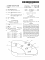
1
US007369116B2
(12)
United States Patent
(10) Patent N0.:
US 7,369,1 16 B2
(45) Date of Patent:
May 6, 2008
Logue
(54)
FOOT-OPERATED KEY PAD
Inventor:
Becky Logues Meridian’
.
.
Notice:
.
Subject to any disclaimer, the term of this
patent is extended or adjusted under 35
USC 154 b b
( ) y
631 d
9/1996 Hayes et a1. .............. .. 345/156
5,745,055 A
4/1998 Redlich et a1.
5,838,305 A *
ays
341/20
11/1998 Bookstein ................. .. 345/163
C
(73) Ass1gnee: Beckmer Products, Inc, Meridian, ID
(US)
(*)
5,552,807 A
t'
d
( on lnue )
FOREIGN PATENT DOCUMENTS
JP
.
09414583
5/1997
(Continued)
OTHER PUBLICATIONS
(21) APP1~ NOJ 10/973,999
Kinesis Programmable Foot Switch (PS/2 Version) User’s Manual,
Aug. 2000 Edition.
(
22
)
El d:
O t. 25 2004
1e
c
’
(Continued)
(65)
Prior Publication Data
Us 2005/0156878 A1
mp 21’ 2005
Primary ExamineriRicardo Osorio
(74) Attorney, Agent, or FirmiPedersen & Co., PLLC; Ken
J. Pedersen; Barbara S. Pedersen
(60)
Provislonal appl1cat1on No. 60/ 513,929, ?led on Oct.
23, 2003.
A foot operated data entry pad has a plurality of foot buttons.
(51)
IIlt- Cl-
bers or symbols separately or in combination. Each button is
(2006.01)
capable of entering different data Values, preferably depend
(52)
(58)
US. Cl. ..................................... .. 345/156; 345/ 163
Field of Classi?cation Search _______ __ 345/156468
ing on the length of time that it is pressed or on the number
of times that it is pressed in succession. A small controller
See application ?le for Complete Search history
_
may be included to allow the user to control the computer’s
pointer, allowing the user to switch between data entry
Related US. Application Data
_
_
_
_
(57)
ABSTRACT
The foot buttons are used to enter data Values4e.g., num
G09G 5/00
(56)
References Clted
?elds, as with a mouse. An automated Voice system, or other
US. PATENT DOCUMENTS
audible and/or Visual indicator system, may also be included
to help the user keep track of the data Value as it changes and
is entered. Various embodiments are capable of entering a
3,943,914
4,446,453
4,904,184
4,922,925
5,144,753
5,197,487
A
A
A
A *
A
A
3/1976
5/1984
2/1990
5/1990
9/1992
3/1993
Grenfell et al. ........... .. 128/2 S
Eenboom et al. .... .. 340/286 M
Murphy et al. ............. .. 433/72
Crandall et al. .......... .. 600/595
Murphy ..................... .. 33/514
Ackerman et al. ..
.. 128/776
5,318,442
A
6/1994
Jeifcoat et al.
8/1994
Scallon ..................... .. 345/167
5,334,997 A *
.....
Variety of alphanumeric data rather than a simple binary
type data set, such as yes/no or on/oiT, or instructions, such
as a joystick used with a ?ight simulator program. Multiple
data entry pads may optionally be used in conjunction.
. . . . . .. 433/72
9 Claims, 8 Drawing Sheets
14
\3
US 7,369,116 B2
Page 2
US. PATENT DOCUMENTS
6,980,133 B2*
7,062,365 B1*
5,886,685 A
5,889,510 A
5,907,318 A *
5,910,139 A
5,993,209 A
6,091,402 A
6,470,222 B1
3/1999
3/1999
5/1999
Best ......................... .. 345/163
Klarlund ..
. 345/168
Medina ....... ..
.345/163
6/1999 Cochran et al.
11/1999 Matoba et al.
7/2000
Howell ........ ..
10/2002 Davidson et al.
6,600,477 B1
7/2003
Howell ..... ..
6,611,250 B1 *
8/2003 Prince et a1~ ~~
6,714,188 B1*
3/2004 Zebuhr et al. ..... ..
6,798,396 B2*
9/2004 Gemunder et a1. ..
2002/0030661 A1
606/1
.. 433/72
12/2005 Foong ....................... .. 341/20
6/2006
Fei ........... ..
3/2002
Gemunder et a1‘
..
701/36
_______ __ 345/156
FOREIGN PATENT DOCUMENTS
JP
09-258887
10/1997
345/157
. 700/2
345/157
OTHER PUBLICATIONS
~~ 345/163
Kinesis Corporation Retail Price List, dated Aug. 22, 2003.
.. 345/156
* cited by examiner
U.S. Patent
May 6, 2008
Sheet 1 6f 8
FIG. 2
US 7,369,116 B2
U.S. Patent
May 6, 2008
Sheet 2 6f 8
FIG. 3
FIG. 4
US 7,369,116 B2
U.S. Patent
May 6, 2008
Sheet 3 6f 8
FIG. 5
FIG. 6
US 7,369,116 B2
U.S. Patent
May 6, 2008
Sheet 4 6f 8
US 7,369,116 B2
1/30
53
FIG. 7
U.S. Patent
May 6, 2008
"1" to PC
__
US 7,369,116 B2
Sheet 5 0f 8
-
_-—
says ‘
-
__
-
-_
-
_______.‘
Voice
says "S"
Second Tier
Transmit
"5" to PC
FIGURE 8
U.S. Patent
May 6, 2008
Button
reieased?
Sheet 6 6f 8
US 7,369,116 B2
Transmits
"1" to PC
held >055?
Transmits
"2" to PC
held >1 .03?
1' Yes
Says "3"
Stop
FIGURE 9
U.S. Patent
May 6, 2008
Sheet 7 6f 8
US 7,369,116 B2
Press
Button
Says "1"
Transmits
"1" to PC
Button
Transmits
pressed?
"2" to PC
Option to say —*>
"Enter" here.
S’EOD
\
(As many layers r
FIGURE 10
as desired)
‘1,
U.S. Patent
May 6, 2008
+
o
MLIYOJQHLA D A
FIGURE 12
Sheet 8 6f 8
"Yo
US 7,369,116 B2
Link- “hi
US 7,369,116 B2
1
2
FOOT-OPERATED KEY PAD
SUMMARY OF THE INVENTION
This application claim priority of Provisional Application
The invention is a foot operated data entry pad designed
Ser. No. 60/513,929, ?led Oct. 23, 2003, and entitled “Foot
for entering informational data over a desired range for
Operated Data Entry Pad,” Which is hereby incorporated by
recordation. In a preferred embodiment, one or more foot
reference.
buttons are provided. Data is entered by pressing the appro
priate foot button. Foot buttons are arranged in a spaced
BACKGROUND OF THE INVENTION
apart, generally radial planar pattern, distanced about 2/3 of
an average foot length (about 5-10 inches) from a heel rest
1. Field of the Invention
This invention relates to data entry devices for computers,
region. Optionally, the heel rest region may also comprise
another sWitch. Preferably, different discreet values may be
entered by pressing the same foot button different lengths of
time or, in an alternative embodiment, by repeatedly press
and more particularly to foot-operated data entry pads.
2. Related Art
As an example of date entry, measuring and recording the
depth of a periodontal pocket caused by a periodontal
ing it.
Additionally, in the preferred embodiment, a joystick
disease, such as gingivitis, is one of the most important
diagnostic activities in dental care. There are many knoWn
pointer, as it is often necessary to move a cursor betWeen
type or other controller is used to control the computer’s
apparatus for taking these measurements. Commonly, these
measurements are entered into a digital database via a
computer. HoWever, conventionally, the dental Worker tak
20
ing the measurements has been unable to enter the data
manually Without having to put the measuring instruments
the mouse and keyboard.
Optionally, the preferred embodiment also includes an
automated voice system that announces entered values and/
doWn and move to a computer keyboard and/or mouse to
record the measurements. Thus, the job is often performed
by tWo or more Workers. Thus, there is a need for such a data
25
entry system that can be operated easily Without the use of
hands.
attaches a foot pedal to an automatic probe used to measure
30
35
40
ever, the sWitch is not used to actually enter any data.
Eenboom, et al. (US. Pat. No. 4,446,453) discloses a foot
pad capable of very simple data entry. This device is capable
of entering a bare yes/no response for the presence of plaque
on a patient’s teeth. Matoba, et al. (US. Pat. No. 5,993,209)
45
also teaches a device that also is used to indicate Whether
plaque is present on a patient’s teeth.
None of these devices are capable of entering information
beyond a simple binary data set4e.g., yes or no, either/or,
50
or on or off.
Also, there are references Which disclose foot-operated
controls for computers. For example, Hayes, et al. (US. Pat.
No. 5,552,807) discloses foot pedal controls for both ?ying
and driving games. Also, Bookstein (US. Pat. No. 5,838,
305) and HoWell (US. Pat. No. 6,091,402) discloses foot
operated control of the position and movement of the
computer’s cursor. Also, Klarlund (US. Pat. No. 5,889,510)
discloses a foot-operated keyboard With tWo arrays of
sWitches4one in the toe-resting region, and one in the
55
60
discloses remote control of surgical and/or dental instru
alphanumeric information.
FIG. 3 is a perspective vieW of one alternative embodi
ment of the invented data entry pad With a schematic shoe
sole included for illustrative purposes.
FIG. 4 is a perspective vieW of the embodiment of FIG.
3 With the schematic shoe sole removed.
FIG. 5 is a perspective vieW of one alternative embodi
ment of the invented data entry pad With a schematic shoe
sole included for illustrative purposes.
FIG. 6 is a perspective vieW of the embodiment of FIG.
5 With the schematic shoe sole removed.
FIG. 7 is a perspective vieW of the embodiment of FIGS.
1 and 2 of the invention in connection With a computer
FIG. 8 is a logical ?oW diagram illustrating the foot button
operation of the preferred embodiment of the invention.
FIG. 9 is a logical ?oW diagram illustrating the foot button
operation of an alternative embodiment of the invention.
ments With a foot pedal controller. HoWever, there is still a
alloWing entry of a Wider range of data, such as numeric or
FIG. 1 is a perspective vieW of the preferred embodiment
of the invented foot-operated data entry pad With a sche
matic shoe sole included for illustrative purposes.
FIG. 2 is a perspective vieW from a slightly different angle
of the embodiment of FIG. 1 With the schematic shoe sole
removed.
system.
heel-resting region. Also Cochran, et al. (US. Pat. No.
5,910,139) and Davidson, et al. (US. Pat. No. 6,470,222)
need for a foot-operated data entry system capable of
Alternatively, the controller and data entry functions may
be separated into tWo separate devices, or the controller
function may be omitted. Multiple data entry pads may also
be used together to increase the capacity of the system.
BRIEF DESCRIPTION OF THE DRAWINGS
a footpad to instruct an instrument to take a measurement
and transmit the reading to a data recording system.
Ackerman, et al. (US. Pat. No. 5,197,487) uses a foot
activated sWitch to sWitch betWeen different modes of opera
tion for analyZing and organiZing data from a probe. HoW
or the current value to be entered if the user releases a foot
button or otherWise ceases to cause the data value to
increment.
For example, Grenfell, et al. (US. Pat. No. 3,943,914)
gingival sulcus. The user positions the probe for measure
ment, and then activates the foot pedal. This triggers the
automatic probe to take a depth measurement and transmit
the result to the data recording system. Other devices, such
as Murphy, et al. (US. Pat. No. 4,904,184); Murphy (US.
Pat. No. 5,144,753); Jelfcoat (US. Pat. No. 5,318,442); and
Matoba, et al. (US. Pat. No. 5,993,209) have similarly used
data entry ?elds. Preferably, the data entry pad Will Work
seamlessly With existing hardWare and softWare by mimick
ing the mouse and keyboardiie, the computer receives
and processes input from the data entry pad as signals from
65
FIG. 10 is a logical ?oW diagram illustrating the foot
button operation of another alternative embodiment of the
invention.
FIG. 11 is a schematic Wiring diagram of the clock line
circuit for the multiplexer of the preferred embodiment of
the invention.
FIG. 12 is a schematic Wiring diagram of the data line
circuit for the multiplexer of the preferred embodiment of
the invention.
US 7,369,116 B2
3
4
DETAILED DESCRIPTION OF THE
INVENTION
The preferred foot buttons 12 are Hall-effect sensors.
They are preferably narroWer than a foot to alloW them to be
closer together and position-error tolerantiif foot buttons
12 Were as Wide as a foot, the user Would have to move his
Referring to the Figures, there are shown several, but not
foot at least one foot-Width betWeen foot buttons 12, and
foot buttons 12 Would have to be spaced at least one
foot-Width apart. If foot buttons 12 are, as in the preferred
all, embodiments of the invented foot operated data entry
pad. As illustrated in FIG. 7, the invented data entry pad
integrates With a larger system that preferably includes a
computer, With its usual accessoriesiie, mouse, keyboard,
and monitor (not shoWn)iand preferably an adapter, called
a multiplexer, that alloWs the footpad to interface seamlessly
With existing computer hardWare and softWare. The pre
ferred multiplexer connects to the data entry pad and the
computer’s other input devicesiie, mouse and key
boardiand controls their respective signals so that the
computer perceives all input as though it came only from the
mouse or keyboard. Thus, With the preferred embodiment,
embodiment, only one-half inch in diameter, then When the
user is pressing one foot button 12, the other foot buttons 12
can be close to the user’s foot on either side. Therefore, the
preferred space betWeen foot buttons 12 is one-half foot
Width plus one-quarter inch, about 3 inches. As a result, the
user only has to rotate the foot by this reduced pitch. This
gives more foot buttons 12 for the same ankle rotation, or
reduces the amount of ankle rotation. Alternatively, heel
support 11 could be designed to alloW the user’s heel to
move laterally, by sliding or lifting it, to reach foot buttons
12 While reducing or eliminating the need for ankle rotation.
there is no need for additional or neW softWare and the data
entry pad can be integrated easily With existing systems.
The term “data” is used herein to refer to information to
be stored for later retrieval. In the preferred embodiment, the
data is an integer referring to the depth of a periodontal
pocket, measured in millimeters. HoWever, the term may
include any information represented by numbers or other
symbols, such as letters, that is stored for later revieW. The
Each foot pedal key can be used for multiple purposes by
20
25
term “data” does not refer to instructions, such as sent by a
controller for a pointer or program operation, such as a video
game control. “Data” also does not refer for this invention
to simple binary data setsiie, Where one of tWo options,
such as yes or no, red or green, or on and off is the only
correct choice.
30
double-clicking or by holding doWn for an extended time.
For example, if the “one” button is held for one second or
longer, it becomes a “?ve”. Voice feedback can say “one” if
the pedal is released before one second, and it can say “?ve”
at the one second point so that the user knoWs to release the
button. In the case of tWo functions per button, the data can
be transmitted either at the transition time or upon pedal
release. Additional functions can be achieved by holding the
button longer still. Also, mouse functions and keyboard
functions can be mixed. For example, holding the “four”
button for one second makes it an “eight” button, but
holding it for three seconds makes it a mouse “right click”
Referring to FIGS. 1 and 2, the preferred embodiment of
the invented data entry pad 10 comprises a heel support 11,
button. If there are three or more functions per pedal, the
data cannot be transmitted until the pedal is released. If there
plurality of foot buttons 12, controller 13, and one or more
controller buttons 14. The user places the heel of the foot on
35 announce the next functional level or can insert a substitute
are three or more functions, the voice feedback can simply
heel support 11 and pivots the foot on that point to reach
each of the foot 12 buttons. The foot buttons 12 are arranged
Word such as “rather” before the function or data name (e. g.,
in a spaced-apart, generally radial planar pattern. This Way,
Referring to FIG. 8, the operation of the foot buttons in
the preferred embodiment for dental application is illus
“rather, nine”).
the data entry pad operator may access each of the buttons
singly, Without disturbing the other buttons. Also, this Way
the operator may access each of the buttons by simply
rotating the foot about the heel Which is in the heel support
40
1, is used for illustrative purposes. Preferably, each foot
button 12 is capable of entering more than one data value.
This is preferably accomplished by making the data value
area 11. Typically, the foot buttons 12 are spaced-apart about
11/2-51/2 inches. Also typically, the foot buttons are distanced
about 2/3 of an average foot length (about 5-10 inches) from
trated. The ?rst foot button 12, With an initial data value of
45
the center of heel support area 11. The foot button radial
entered dependent on Which foot button 12 is pressed and on
hoW often or on hoW long it is continuously pressed.
To enter a given data value, the user presses the appro
priate foot button 12, but the data value is preferably sent to
computer 51 only after foot button 12 is released. For
pattern may extend in an expanding pie shape out from the
heel support area 11 from about 30° to abut 150°, depending
upon the number of buttons in the pattern. The buttons may
example, if the chosen foot button 12 is released before a set
be present in one or more roWs. When there are multiple 50 time periodipreferably one secondihas passed, the initial
roWs of buttons, preferably they are staggered to maximiZe
data value associated With the chosen foot button 12 is
distance betWeen the buttons. As described in more detail
transmitted to an automatic voice system, Which announces
beloW, the data value sent to the computer preferably
the data value, and to the computer system for recording. As
illustrated in FIG. 8, the resulting data value Would be 1. The
other three foot buttons 12 have initial data values of 2, 3,
depends on Which foot button 12 is pressed and also on the
number of times, or the length of time, that it is pressed. As
illustrated by the inclusion of foot sole 60 in FIG. 1,
55
and 4. If the foot button is not released in less than the set
period of timeiie, one second for the preferred embodi
mentithe initial data value is increased by four, and the
controller 13 and controller buttons 14 are preferably
beyond the reach of the user’s foot When the heel is touching
heel support 11 to prevent accidental activation of controller
13 and/or controller buttons 14. Other foot buttons 12 could
neW value is sent to the automated voice system for
60
be added to the data entry pad to mimic, for example, the
shift key, control key, or mouse buttons, etc. Alternatively, a
controller button 14 may be replaced by designing heel
support 11 to register and transmit a signal4e.g., either
mouse button signaliWhen heel support 11 is pressed doWn
by the user’s heel. In some applications, one or both of
controller buttons 14 could be omitted.
65
announcement, but not to the computer system. The data
value is sent to the computer system once the foot button is
released. Optionally, the data value could be reannounced as
entered at this point.
In the preferred embodiment, each foot button 12 is
associated With tWo data values4e.g., 1 and 5 for the ?rst
button, as illustrated in FIG. 8icovering the integers from
one to eight, inclusive. Although the preferred embodiment
US 7,369,116 B2
5
6
permits entry of only a small range of data values, any
data values until the button is not re-pressed Within the
preset time period. At that point, the last data value is sent
to the computer system. As With the other embodiments,
appropriate data values can be chosen as the upper and loWer
limits, including no upper limit or in?nity4or an upper
limit, and no loWer limit With descending rather than ascend
limits on the range or data values enterable may be imposed
ing numbers. Thus, continuing to hold foot button 12, in this
example, could result in the data value increasing by fouri
i.e., to 9, 13, etc.iin?nitely or, preferably, to any appro
priate maximum for a given application. Also, the increment
for convenience, but are not required. LikeWise, the incre
ment betWeen data values may be set at any amount appro
priate for a given application.
The techniques discussed above relating to FIGS. 8-10
betWeen data values need not be one, or any other value, but
can be set at any appropriate amount for a given application.
With timing or repeat features amount to a code of actuation
Besides,
Most people are not able to accomplish ?ne motor move
ments With their feet. Therefore, it is a further aspect of this
for the foot buttons(s).
[1] This routine is for each button. Any number of buttons
can be used.
invention to develop a joystick Which can precisely position
[2] Digit entry is shoWn here, but entry can be any digit,
character, symbol, Word, phrase, etc., that is desired to be
a cursor on a computer screen, but Which doesn’t require
entered into the PC.
[3] Wait times betWeen increments can be set to any value
that it is on or off, rather than proportional. If it is pressed
up, the cursor begins moving up. If it is released, the cursor
accurate foot movements. The joystick is digital, meaning
to optimiZe usability.
stops. The joystick does not control cursor position or cursor
[4] More tiers of increments can be added. The voice says
something neW after each increment time period, but the
entry is not transmitted until the button is released.
speed. It only controls approximate direction of travel. In the
preferred embodiment, the joystick Will only move in eight
20
discrete directions (up, right, 45 degrees up and right, etc.).
Referring to FIG. 9, the operation of the foot buttons in
Alternatively, the joystick could be made to move the cursor
one alternative embodiment is illustrated. In this example,
the initial data value is 1 and increases by increments of 1.
This could be the case Where there is only one foot button
12, Where the initial data values for other foot buttons 12 are
in any direction. The cursor can move at a constant speed,
25
but in the preferred embodiment, it starts out sloWly and then
increases its speed more as the joystick is pressed longer. In
this Way, quick on-and-olf, in a form of “dithering”, motions
non-integersie.g., 1.25, 1.5, and 1.75ior Where other foot
can achieve very ?ne cursor manipulation, While pressing
buttons 12 operate for number ranges Wholly greater or
lesser than those for the foot button 12 in the exampleie.g.,
the joystick longer can cause the cursor to traverse the screen
one button could be used to enter values from 1 to 10,
another to enter values from 11 to 20, and so on. In the
30
embodiment of FIG. 9, the button is held doWn until the
desired entry is heard. Then upon releasing the button, the
entry is transmitted to the PC. The set time period after
Which the data value is increased is 0.5 seconds rather than
in a reasonable amount of time. Although applicable to foot
operation, this feature of the invention can also be used for
a hand-operated device for those Who cannot perform ?ne
motor movements With their hands.
In the preferred embodiment, the user is able to perform
any point-and-click operations that the user’s softWare
35
includes With controller 13 and one or more controller
the 1.0 second of the preferred embodimentiany time
period can be chosen, but it should preferably be long
buttons 14. The preferred controller 13 is a short joystick.
Alternatively, a rocking panel may be used. Controller 13
enough for the user to release the foot button 12 before the
data value changes Without being so long as to make the
device unproductively sloW. No limit to the values that can
be entered is shoWn in the embodiment of FIG. 9, but one
could be added. Likewise, any increment betWeen data
values may be chosen, depending on the needs of any given
controls the cursor by causing it to move in a chosen
40
off-center. Preferably, one or more controller buttons 14 are
placed to one or both sides of controller 14. Alternatively, a
controller button 14 may placed in the center of the con
troller so that When the controller is released, the button is
released and activated to send a computer mouse left or right
application. When the chosen foot button 12 is pressed, the
initial data value is sent to the automated voice system and
announced. Each time the data value changes, it is sent to the
automated voice system and announced. The data value is
sent to the computer only after the chosen foot button 12 is
released. Optionally, this data value could be re-sent to the
automated voice system and reannounced as entered.
button signal to computer 51. Because controller 13 and
controller buttons 14 are placed beyond the reach of the
user’s foot When the foot is contacting heel support 11, the
user moves his foot forWard from heel support 11 to operate
50
Referring to FIG. 10, the operation of the foot buttons in
another alternative embodiment is illustrated. In this varia
controller 13 and controller buttons 14. In the preferred
embodiment, controller buttons 14 mimic the functions of
the left and/ or right mouse buttons.
Digits or other data can be input using one of several foot
pedals or buttons. Alternatively, the heel or foot can rest on
tion, the button is pressed and released until the desired entry
is heard. Then When the button has been released for over 1/2
second, the entry is transmitted to the PC. In this case, a
direction. Optionally, the speed of the cursor may be adjust
able and/or increasing the longer controller 13 is held
55
chosen foot button 12 is pressed, released, and re-pressed
a pivoting platform, pad, cradle, or footrest. When the
pivoting member rotates about an axis roughly parallel With
Within a set period of time to enter a data value. Like the
the ankle, its rotational position may be sensed by optical,
embodiment of FIG. 9, the initial data value is one and the
increment betWeen data values for a foot button 12 is 1.
mechanical, Hall-effect, proximity, or other means and is
interpreted as being in one of N positions. For example, four
discrete positions can be detected using only tWo discrete
detectors. If the detectors are optical, then an interrupter,
When the appropriate foot button 12 is pressed, the associ
60
ated initial data value is announced. When the button is
released, the device Waits a preset period of timeiin this
case, 0.5 secondsito see Whether the button is re-pressed.
If the button is not re-pressed, the data value is sent to the
computer system. If the button is re-pressed during the
cam, or re?ector plate could trigger only the ?rst detector,
65
both detectors, only the second detector, or no detectors.
Depending upon Which of these four combinations is
detected, the correct data is selected for transmission. Then
preset time period, the data value is incremented and the neW
the data can be entered, for example, by rocking the pivoting
value announced. This process is repeated With increasing
foot device about a second axis roughly perpendicular to the
US 7,369,116 B2
8
7
?rst. When the foot device rocks, it detects the rotational
There are several Ways to accomplish this multiplexing or
motion. Alternatively, the foot could rock forward (Whether
“Wye” connection.
the foot device pivots or is shaped to alloW the foot to rock)
a) An 8-pole, double throW sWitch could connect the four
mouse lines and four keyboard lines from the computer to
either the keyboard and mouse, or to the foot pedal and
and touch a button or bar or be sensed in another Way to
activate a sWitch, and initiate an entry.
Referring to FIGS. 3 and 4, one alternative embodiment
joystick device.
b) All the ground/common/negative lines could be per
manently connected together and a 6-pole, double throW
is data entry pad 10' With only controller 13 and controller
buttons 14 is shoWn. Controller 13 and controller buttons 14
sWitch can be used to connect the remaining lines.
function as in the preferred embodiment, described above,
c) Adding a large capacitor betWeen poWer and ground
except that the user can operate controller 13 and controller
lines on the computer side of these sWitches could minimize
buttons 14 Without moving his feet forWard from heel
support 11, as illustrated by foot sole 60 in FIG. 3. In this
embodiment, there is no foot button 12. HoWever, controller
buttons 13 and 14 may be actuated With a simple heel
rotation before applying pressure on buttons 13 and 14 With
the effects of hot sWitching.
d) The ground/common/negative lines could be perma
nently connected together, the poWer lines could be perma
nently connected together, and then a 4-pole, double throW
the toes or ball of the foot.
This requires that poWer consumption of the foot pedal
sWitch Would connect the tWo data lines and tWo clock lines.
Moving on to FIGS. 5 and 6, an alternative embodiment
device plus keyboard and mouse to be loW enough to ?t
of data entry pad 10" is shoWn. It is shoWn With three foot
Within the PS/2 speci?cation for computer-supplied poWer.
e) Same as (d) above, but poWer is augmented With a Wall
transformer. For example, if optical detectors are used, their
buttons 12, and With no controller or controller buttons. Foot
20
buttons 12 function as in the preferred embodiment,
LEDs could be poWered by an auxiliary poWer source.
f) The sWitches in the scenarios above could be replaced
described above, except that the interval betWeen data points
is three rather than four because of the number of foot
buttons 12 included. Preferably, the tWo embodiments in
FIGS. 3-6 are used in conjunction, giving the user all the
capabilities of the preferred embodiment. The user may
operate each device With a separate foot or may sWitch his
foot back and forth, as the user prefers.
by solid-state sWitching devices or relays.
25
g) The scenarios above all require the user to ?ip a sWitch
to change betWeen devices. A smart technique Would alloW
input to be received from any device Without user interven
tion. The user should be alloWed to seamlessly sWitch from
keyboard to foot pedal and mouse to joystick, and vice
Referring to FIG. 7, the preferred embodiment of data
entry pad 10 is illustrated connected to a typical computer
30 versa. One Way to accomplish this is to use one or tWo
system 50 used for data entry. Data entry pad 10 is connected
the peripheral devices and the PC. In PS/2 communication,
to multiplexer 30. Mouse 53 and keyboard 52 are also
connected to multiplexer 30. Multiplexer 30 is connected to
computer toWer 51 via tWo cords, Which connect to the
the PC is the host. If the micro-controller acted like a host
to the keyboard and mouse it could receive their input data
micro-controllers to manage the communication betWeen
35
computer’s mouse and keyboard ports (not shoWn). Multi
plexer 30 receives signals from keyboard 52, mouse 53, and
data entry pad 10. Signals from data entry pad 10 are
identi?ed as mouse-type or keyboard-type signals. Signals
from all input devices are prioritiZed and sent to the appro
40
priate computer portiie, the mouse or keyboard port.
Although the preferred embodiment is shoWn connected to
pass signals in near real time, mimicking the clock and data
computer system 50 via Wires, any or all of the connections
may be Wireless using any Wireless technologyieg, meth
45
ods used for a Wireless mouse or Wireless laptop connec
tions.
Ideally, the data input device should be connected to the
computer in a Way that is invisible to the application
softWare. Connecting to the serial port Would require modi
fying application softWare to look for data input at that port.
50
Connecting to a USB port is simple, but in some cases Will
require installing special driver softWare. This is a reason
able approach, as it Will be invisible to the application
softWare that is manipulating or storing the data. The pre
mouse or joystick, or Whether data is coming from a
h) A micro-controller betWeen a keyboard and PC or
betWeen a mouse and PC Will cause signal delays Which
could potentially result in malfunction. Therefore, the pre
60
Unplugging the keyboard and mouse to connect the foot
ferred embodiment uses MOSFETs and diodes to connect
and disconnect the signals betWeen these devices. See the
FIGS. 11 and 12 folloWing. The clock and data lines of a
PS/2 port are open collector; they ?oat high With the help of
pedal, then changing back for hand-typing additional data
Would be unacceptable, especially because the computer
keyboard and foot pedal is required.
the micro-controller is sending data from the foot pedal to
the PC, it can pull the keyboard clock line loW to inhibit the
keyboard. The keyboard Will bulfer any data it has to send
until the clock line goes high. In this Way, data from the
keyboard, mouse and foot pedal can be inter-mixed (multi
plexed) to be fed to the PC in the order it is input by users,
and at a speed still exceeding the user’s ability to enter the
data. Data from all devices gets processed and the computer
keyboard or foot pedal.
through the mouse and keyboard PS/2 ports. This is Where
the computer and application softWare receive their data and
must be turned off to plug and unplug devices to the PS/2
ports. Therefore, a means to mix or multiplex the signals
from mouse and joystick and mix the signals from the
signals from a peripheral or PC, or it could process one data
byte or packet at a time before relaying it to the PC. While
cannot tell Whether a cursor movement Was initiated by a
55
ferred embodiment is to input data and cursor movement
cursor instructions.
and could also receive data from the foot pedal. Then the
micro-controller could act like a slave to the PC, looking like
a keyboard and mouse. In this Way it could input the data
from all devices While looking like one keyboard and one
mouse. Communication betWeen the foot pedal and micro
controller could be PS/2, I2C, or any other proprietary or
standard protocol, or the foot pedal sensors could input
directly to the micro-controller. The micro-controller could
a resistor and can be pulled loW by either the PC or
65
peripheral device (keyboard or mouse). When the devices
are connected (MOSFETs are turned on by pulling gates
high), the keyboard or mouse can communicate directly With
US 7,369,116 B2
10
the PC and there is essentially no signal delay. The device
pulls the clock line loW through the MOSFET and pulls the
data line loW through the diode. The PC pulls the device
clock line loW through the diode and pulls the data line loW
through the MOSFET. When the MOSFETs are turned off
entry ?eld on the screen. The next measurement is taken and
recorded4e.g., a 5. The ?rst foot button of the data entry
pad is pressed and held until the data value is incremented
to 5. It is then released and the data value is recorded. This
5
(gates are pulled loW), the device is disconnected, the device
is inhibited by pulling its clock line loW, and the clock and
alWays taken in the same order, and the softWare is adapted
data lines on the PC side can be manipulated by the
micro-controller to communicate foot pedal information to
the PC. In this disconnected state, the device clock line is
already loW, so clock transitions on the PC side Will not be
to receive this order of measurements, there may be no need
for controller use betWeen the measurements.
Although the invention has been described as applied to
recording the depths of gingival sulcus, it may be used to
changing the clock line through the diode, but the diode
enter data for any purpose Without exceeding the scope of
the invention.
Although the invention has been described as including
one data entry pad, a second pad could be added. The user
could use both feet and the number of foot buttons that could
alloWs the line to go high. When the device is inhibited, it
Will let its data line ?oat high. The data line on the PC line
can go high and loW While being isolated from the device by
the diode.
i) A further aspect of the invention is that the micro
controller can monitor communication betWeen a device and
the PC. One use of this is to determine Which kind of mouse
to emulate. The PC queries the mouse at start-up to deter
mine Which kind of mouse it is, and therefore knoWs hoW to
read and interpret the mouse information it receives. If the
micro-controller monitors this communication, it can then
emulate that same kind of mouse in its communication. This
20
alloWs the multiplexer to be universal in application With
25
described as having four foot buttons, it is not limited to any
j) Although less user friendly, a simpler implementation to
9, With a decimal point as needed, to input data values.
The invention preferably includes an automated voice
system that announces data values at various points in the
30
system’s operation. Any conventional automated voice sys
tem may be used, and the voice may be broadcast from a
k) Watching PC-to-mouse communication also alloWs the
35
built-in speaker(s) or over the computer system’s audio
system4e.g., by adding a connection to the computer’s
microphone jack. Alternatively, a simpler system, such as an
audible beep, may be used to indicate that, for example, a
data value has changed. HoWever, this is less preferred
because it increases the probability that the user Will acci
dentally, and possibly unknoWingly, enter an incorrect data
transmits a foot pedal command to see if the PC sends a
“resend” command. If so, the micro-controller must retrans
mit its last data.
enter any numerical range just as a standard number pad on
a keyboardiie, the data entry pad enters digits 0 through
select betWeen the most common mouse types is to use
micro-controller to capture and emulate the same resolution,
scaling, and other factors relevant to cursor movement.
m) The keyboard or mouse can be kept in an inhibited
state for several milliseconds after the micro-controller
be included Would be expanded. Also, the invented foot
operated data entry pad may be adapted to input other than
numerical data. For example, by adding foot buttons and
using tWo data entry pads, the invention could be used to
enter other types of data, such as alphanumeric symbols,
Words, or phrases. Although the embodiments have been
particular number of foot buttons and may be adapted to
any standard PS/2 mouse.
con?guration sWitches set at the factory or by the user. For
example, one setting Would cause three-byte mouse packets
to be transmitted and another setting Would cause four-byte
mouse packets to be transmitted.
process continues until all necessary measurements are
taken and recorded. In cases Wherein the measurements are
40
value.
Although this invention has been described above With
n) If the voltage drop across the Schottky diode is
problematic, then an open-collector op-amp/comparator cir
reference to particular means, materials, and embodiments,
cuit can be used as a buffer to folloW signals to their
loW-level state. A rail-to-rail op-amp Will achieve an almost
disclosed particulars, but extends instead to all equivalents
Within the scope of the Description, DraWings, and folloW
perfect Zero voltage.
0) Many N-type MOSFETs have a diode betWeen their
source and drain. If their voltage drop is not a problem, then
it is possible to implement the circuit Without the external
diode shoWn in the sketch.
Although the invention is shoWn at one siZe, various
methods may be used to accommodate various siZes of feet.
For example, models may be made in different siZes. More
preferably, heel support 11 may be made adjustable so that
it may be moved forWard or backWardiie, along a line
passing through the center of heel support 11 and controller
13. The adjustment method may be continuousiie, may be
set at any point4or have discreet settingiie, a plurality of
it is to be understood that the invention is not limited to these
45
I claim:
1. A data entry pad for a computer comprising a plurality
of foot buttons, said foot buttons being con?gured to enter
50
being distanced about 5-10 inches from the center of a heel
support area also on said pad.
55
3. The pad of claim 1, Wherein the code of actuation
depends upon hoW many times the buttons are depressed,
60
one to eight, inclusive. For example, the user Would take a
measurement With an instrument4e.g., a 3. The third foot
button of the data entry pad is then pressed and promptly
used to move a cursor, or similar pointer, to another data
2. The pad of claim 1, Wherein the code of actuation
depends upon hoW long the buttons are continuously
depressed.
The preferred embodiment is designed for entering peri
released to enter this value. If necessary, the controller is
different data values according to a code of actuation of the
foot buttons, the buttons being spaced-apart in a generally
radial planar pattern on said pad, each of said foot buttons
locking points.
odontal dataie.g., the depth of gingival sulcus. Based on
the needs of this application, the preferred embodiment has
four foot buttons and is capable of entering data values from
ing Claims.
65
released, and re-depressed.
4. The pad of claim 1, Which comprises a cursor controller
further from the heel support area than said foot buttons.
5. The pad of claim 4, Which comprises a mouse control
button further from the heel support area than said foot
buttons.
6. The pad of claim 4, Which comprises a mouse control
button in the heel support area.
US 7,369,116 B2
11
12
8. The key pad of claim 7, Which comprises a plurality of
7. A foot key pad for a computer, Which comprises a
cursor controller and a mouse controller button, the cursor
mouse controller buttons.
controller and mouse controller button being spaced-apart in
a generally radial planar pattern on said pad, and both said
9. The key pad of claim 8, Wherein one mouse controller
button is in the heel support area.
cursor controller and said mouse controller button being
distanced about 5-10 inches from the center of a heel support
area also on said pad.
5