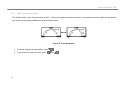
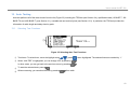
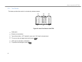
1
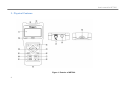
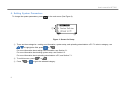
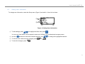
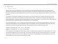
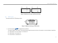
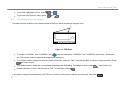
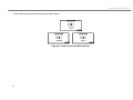
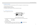
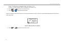
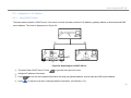
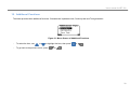
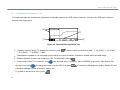
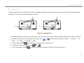
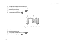
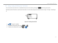
99 Washington Street Melrose, MA 02176 Phone 781-665-1400 Toll Free 1-800-517-8431 Visit us at www.TestEquipmentDepot.com NET200 User’s manual for NET200 User’s manual for NET 200 LIMITED PRODUCT WARRANTY AND LIMITATION OF LIABILITY Megger warrants its products and accessories to be free from defects in materials and workmanship under normal consumer usage for periods(s) outlined below. This warranty is not transferable and valid only to the original buyer or end-user. Megger shall not be liable for any direct, indirect or consequential loss arising or damages suffered resulting from the usage of any of its products herein or any other products used in conjunction with. WHAT IS COVERED: COVERAGE LENGTH OF COVERAGE NET200 MAIN UNIT One (1) year from the date of purchase by the original buyer or end-user PARTS AND ACCESSORIES Ninety (90) days from the date of purchase by the original buyer or end-user BATTERIES Ninety (90) days from the date of purchase by the original buyer or end-user SOFTWARE Ninety (90) days from the date of purchase by the original buyer or end-user WHAT IS NOT COVERED: Normal wear and tear, abuse & misuse, usage of non-Megger or non-Megger certified products/accessories, unauthorized service and modification, altered products and error free software or operation without interruption. User’s manual for NET 200 CONTENTS 1. Safety Information ................................................................................................................. 1 2. 3. Overview of Features ............................................................................................................ 3 Physical Features .................................................................................................................. 4 4. Connecting Cables ................................................................................................................ 6 5. Getting Started ...................................................................................................................... 7 6. Setting System Parameters................................................................................................... 8 6.1. 7. 8. 9. Setting User Information ............................................................................................. 9 6.2. Setting System Setup ............................................................................................... 10 Communication with External Devices ................................................................................ 12 7.1. Uploading Stored Data to a PC................................................................................. 12 7.2. Printing Test Results ................................................................................................. 12 TDR Testing ........................................................................................................................ 14 8.1. Operation Principles.................................................................................................. 14 8.2. 8.3. TDR Function ............................................................................................................ 15 LAN Graphic and Coax Graphic ............................................................................... 16 8.4. LAN Numeric............................................................................................................. 21 8.5. Coax Numeric ........................................................................................................... 22 8.6. Assigning Mode to Arrow Buttons and Selecting Pulse ............................................ 23 8.7. Measurement Accuracy and VOP............................................................................. 23 Crosstalk Testing................................................................................................................. 25 9.1. Numeric Test............................................................................................................. 26 User’s manual for NET 200 9.2. Graphic Test ............................................................................................................. 28 10. Wiremap Testing ................................................................................................................. 29 11. Network Analysis ................................................................................................................. 31 11.1. Inspecting Activity of the Port.................................................................................... 31 11.2. Assignment of IP Address......................................................................................... 33 11.2.1. Using DHCP Server ......................................................................................... 33 11.2.2. Assigning a Static IP Address .......................................................................... 34 11.3. Link Blink ................................................................................................................... 35 11.4. PING Test ................................................................................................................. 36 11.5. Collecting Network Information ................................................................................. 36 12. Additional Functions ............................................................................................................ 39 12.1. Characteristic Impedance Test ................................................................................. 40 12.2. Continuity Test .......................................................................................................... 41 12.3. Tone Generating Function ........................................................................................ 42 13. Auto Testing ........................................................................................................................ 43 13.1. Selecting Test Functions........................................................................................... 43 13.2. Test Results .............................................................................................................. 44 13.3. Saving, Loading and Deleting Auto Test Results...................................................... 47 14 Maintenance ........................................................................................................................ 48 14.1. Charge ...................................................................................................................... 48 15 Specifications ...................................................................................................................... 50 rev. 2-3 User’s manual for NET 200 1. Safety Information Safety Caution This product complies with the safety requirement of EN 61010-1:2010. This tester does not generate any hazardous voltages, and is designed to be used on de-energized circuits only. Connections to any main supply voltage will result in damage to the tester and/or a hazard to the user. The user must assume responsibility for ensuring his, or her own safety. The BNC plug and socket are, by necessity, accessible. The outer sheath for this connector is always at SELV levels. CAUTION 1. Do not connect to telephone networks or outside wiring. This will damage the NET200 and presents an electric shock hazard. 2. Verify that the system under test is de-energized before using the NET200. 3. Disconnect all cables from RJ45 and BNC connectors before charging or connecting to PC. 4. Check that all lead connections are correct before making a test. 5. Use only certified charger, please follow the user's manual. See Section 14.1 6. Refer to operating instructions for further explanation and precautions. 7. Safety warnings and Precautions must be read and understood before the instrument is used. They must be observed during use. 8. Any replacement battery pack must be fitted only by a Megger service centre. The battery must be disposed of according to local waste directives. Do not dispose of the battery to landfill or incinerate it. 1 User’s manual for NET 200 Symbols used on the Tester Caution! See explanations in this manual. Battery. Tester complies with the current EU Directives. Tester complies with the WEEE Directives.(2002/96/EC) and must not be disposed of in the waste stream LAN ONLY (Do not connect to the telephone line.) International Standards Safety - IEC61010-1:2010 EMC - The equipment meets the European EMC directive 2004/108/EEC : and FCC47 Part 15(B) Class A - EN61326-1:2006, and EN61000-3-3:2008 EMC - FCC47 CFRPart 15 Subpart B – Unintentional Radiators. - This equipment has been tested and found to comply with the limits for a Class A digital device, pursuant to Part 15 of the FCC Rules and EN61326:2006, CISPR11. These limits are designed to provide reasonable protection against harmful interference when the equipment is operated in a commercial environment. This equipment generates, uses, and can radiate radio frequency energy and, if not installed and used in accordance with the instruction manual, may cause harmful interference to radio communications. Operation of this equipment in a residential area is likely to cause harmful interference in which case the user will be required to correct the interference at his own expense. NOTE THE INSTRUMENT MUST ONLY BE USED BY SUITABLY TRAINED AND COMPETENT PERSONS 2 User’s manual for NET 200 2. Overview of Features NET200 is an MTDR (Metallic Time-Domain Reflectometer) device that can measure the cable length and diagnose cable defects such as a break (open), shorted-circuit and sudden change of impedance (such as, repeaters) in graphic and numeric formats. It also includes many useful functions such as the Crosstalk test, Wiremap test and Network (TCP/IP) analysis that can be used to test & compare the cable (and network) to satisfy required network standards. In addition, NET200 provides a Tone-generating function used to identify and trace the cable in cavities (such as walls, floors, etc.). It also provides a Continuity-test function to check out the continuity of the cable. NET200 is a high-tech all-in-one instrument suitable for installing, repairing and maintaining business network services based on UTP/STP cables, Coaxial cables, Telephone cables, and other metallic cable pairs cost effectively. The tester comes with the accessories listed below. If an item is damaged or missing, contact your supplier immediately. Standard Accessories Optional Accessories Remote Identifier #1 User’s Manual Remote Identifier #2 BNC to F connector Battery Pack Manual Remote Identifier #3 PC program CD Remote Identifier #4 Download cable (USB-RS232C) Remote Identifier #5 AC-DC Adapter (12V / 1.5A) Remote Identifier #6 Test Lead cable (30cm) Remote Identifier #7 Power Cord (UK/US/EU) Remote Identifier #8 Portable bag Automobile Cigarette Lighter Charger(12V) Pouch Mobile printer (3rd party) 3 User’s manual for NET 200 3. Physical Features Figure 1. Exterior of NET200 4 User’s manual for NET 200 ① LCD display with backlight. ② BNC connector for connecting to coaxial cable or the alligator clip (a standard accessory), ③ 8-pin modular (RJ45) connector for connecting to twisted pair network cables. ④ Function buttons. These buttons provide functions related to the current screen, the specific function is shown on the screen above the buttons. ⑤ Power on/off button. ⑥ Backlight on/off button. Additionally, pressing this button for more than three seconds will turn on/off the button sound. ⑦ Setup button for selecting test parameters. ⑧ Mode button for selecting action of the arrow buttons – zooming and scrolling waveform, moving cursors. ⑨ Exit button. ⑩ Print button. ⑪ Arrow buttons, used to navigate the cursor through screen options. ⑫ OK button for selecting the highlighted item in the menu. ⑬ RS-232C port for uploading saved test results to a PC and printing current test results. ⑭ LED for indicating charge status. 5 User’s manual for NET 200 4. Connecting Cables Before connecting cables, be sure to check the following: 1. Power sources (over 6.5 volts) should not be connected to the far end of the cable. 2. Cable must be connected to only one of the two connectors: BNC connector (② in Figure 1) or RJ45 connector (③ in Figure 1). Depending on the cable you want to connect, you can use: Coaxial Cable Connect it directly to the BNC connector. Shielded Twisted Pair Connect it directly to the RJ45 connector. (STP) Cable Unshielded Twisted Pair Connect it directly to the RJ45 connector. (UTP) Cable Unshielded Multi-Core After connecting the alligator clip lead to the Cable BNC connector; choose one pair of the cable using the alligator clips. The tester is not intended to be connected to active systems, or equipment. Prolonged exposure to the voltages applied by these interfaces may damage the tester. If the tester detects voltage over 6.5V, a “WARNING” screen is displayed. Disconnect the tester if the voltage warning symbol appears. 6 User’s manual for NET 200 5. Getting Started Press more than three seconds; the display turns on and shows the Main Menu. ② ③ ① Menu selection area. To select a function, use ④ press ① ⑤ ⑧ ⑨ ⑥ ⑩ ⑦ or to highlight the item; . ② TDR test. (See page 14) ③ Wiremap test. (See page 29) ④ Network analysis. (See page 31) ⑤ Crosstalk test. (See page 25) ⑥ Additional test functions. (See page 39) ⑦ Auto test. (See page 43) ⑧ To change the system parameters, press or . ⑨ Battery gauge. Figure 2. Main Menu ⑩ To select the item, press or when highlighted. 7 User’s manual for NET 200 6. Setting System Parameters To change the system parameters, press in the main menu (See Figure 2). ① ② ③ Figure 3. Screen for Setup ① There are three categories – setting user information, system setup, and uploading stored data to a PC. To select a category, use to highlight the field; press or . For more information about setting user information, see Section 6.1. For more information about setting system setup, see Section 6.2. For more information about uploading stored data to a PC, see Section 7.1. ② To exit this menu, press ③ Press 8 or or . to go to the selected category. User’s manual for NET 200 6.1. Setting User Information To change user information, select the Setup menu (Figure 3) and edit in 1.User Info as below. ① ② ③ ④ Figure 4. Setting User Information ① To edit settings, press to highlight the field; then, press . You can use “User Name” as the operator’s name and “Affiliation” as an abbreviated company name. ② Use the buttons to select the character and then use ③ To exit this menu without saving changes, press ④ To store the changes, press or to change the highlighted character. . . 9 User’s manual for NET 200 6.2. Setting System Setup To change system settings, access the Setup menu (Figure 3) and edit in 2.System Setting as below. ① ③ ② ④ Figure 5. System Setting ① To edit settings, press ② Pressing ③ When in edit mode the cursor will blink. Press Pressing to change the number; press or . changes parameter values. To exit this menu, press ④ to highlight the field, then press or to retain the present value. after or before changing values – at this point, the cursor is not blinking. selects or confirms, or starts the selected function. To alter the screen contrast, change the number in ‘LCD Contrast’ (min=1 max=11). To alter the auto-off feature, change the ‘Auto Power’ setting to the number of minutes required before auto-off. To make the new settings your default, toggle the ‘Backup mode’ to ON. Leaving ‘Backup Mode’ set to OFF means that the changes are effective for the current session only. 10 User’s manual for NET 200 To change the MAC address of the tester, choose the 4th item in Figure 5 and enter the new MAC address in ① below. ① ② ③ Figure 6. Setting MAC Address ① The MAC address field consists of 6 numbers between 0 and 255 (hexadecimal, 00h ~ ffh). moves the cursor and changes the highlighted character. Available characters are 0, 1, 2, 3, 4, 5, 6, 7, 8, 9, a, b, c, d, e, f. ② To exit this menu and save the changes press ③ To exit this menu without saving changes press . . To alter the length units, change the ‘Unit’ setting. (Feet/Metre) You can reset the tester to default settings (6th item in Figure 5); the tester asks for confirmation. Highlight your choice using press then to accept (Note the exit key is available to cancel). 11 User’s manual for NET 200 7. Communication with External Devices 7.1. Uploading Stored Data to a PC To upload stored data to a PC, select the Setup menu (Figure 3) and edit in 3.Upload to PC as below. Figure 7. Uploading Screen After connecting the tester to the PC, press or to start the download (Ensure the software is running on the PC). Be sure to disconnect all cables from RJ45 and BNC connectors before connecting to a PC. 7.2. Printing Test Results The test results, including the measured waveforms, can be printed using the optional printer and a printer cable. After connecting the printer to the tester, press 12 to start printing the results for the current test. User’s manual for NET 200 ① ② ③ ④ Figure 8. Printing Screens ① Printer is connected and tester is ready for printing. ② The tester cannot detect an attached printer. ③ Printer is not connected. ④ An error has occurred during printing. Check the printer or refill printer paper; then try again. The optional printer listed is the only one recommended for printing. Be sure to disconnect all cables from RJ45 and BNC connectors before connecting to a Printer. 13 User’s manual for NET 200 8. TDR Testing 8.1. Operation Principles When an electric pulse is transmitted from one end of a cable, this electrical signal travels through the cable, and its reflected signal is generated where propagation characteristics (characteristic impedance) of the cable are changed; these points are defined as the “events.” By measuring the shape of the reflected signals and the times they take to reach the tester, the types of and the distance to the events can be determined. The changes in the characteristic impedance are often caused by open or shorted cables. Figure 9 shows the waveforms of the signals measured by the tester when a pulse is initiated into two cable conditions. Position represents where the pulse signal is applied to the cable, and the Position represents where the reflected signal is, from open or shorted cables. In an open cable, both the initial pulse and its reflected signal have the same polarity while the inverse polarity occurs in a shorted cable. The interval between Position and corresponds to the time difference between the transmitted and the reflected pulse, which can be used to calculate the distance to the point of impedance change. In this calculation, the velocity of propagation (VOP) is used; VOP is the speed of the electrical waves propagating through a cable, which depends on the unique characteristics of each cable. VOP is expressed as a percentage of the speed of light in vacuum. For example, when we say the VOP of a cable is equal to 66%, it means that the signal propagates at 66% of the speed of light. The VOP value is affected by the type of a cable’s metal conductor, by its insulating material, and by its structure. For communication cables, their VOP values are normally listed as one of the specifications provided by the cable manufacturers. Typical VOP values are between 30% and 90%. 14 User’s manual for NET 200 ① ② ① ② Figure 9. Waveforms for Open and Shorted Cables 8.2. TDR Function The tester provides four TDR testing unctions. ① ③ ② Figure 10. Menu for Selecting a TDR Function ① Use the arrow keys to highlight the required test. The words “Graphic” and “Numeric” mean that the tester shows the results in the form of a waveform or numeric displays, respectively. For “LAN Graphic” and “Coax Graphic”, see Section 8.3 For “LAN Numeric”, see Section 8.4. For “Coax Numeric”, see Section 8.5. 15 User’s manual for NET 200 ② To start the highlighted function, press or ③ To go back to the previous menu, press 8.3. . or . LAN Graphic and Coax Graphic The tester plots the reflections on a distance scale to show you where impedance changes occur. ① ② ③ ④ Figure 11. TDR Plots ① To position “CURSOR1” and “CURSOR2”, use with the mode set to “CURSOR1” and “CURSOR2” respectively. (See Section 8.6) The cursors must be located at the beginning of reflections. ② The numbers shown indicate the pair being used on the RJ45 connector. “BNC” indicates the BNC connector is being monitored. Press to select the pair. ③ The “Mode indicator” shows the current display operating mode and setting. To change its mode, press ④ Distance (between Cursor1 and Cursor2) or VOP. To swap them, press . If you want to change the parameters for the TDR test, save the current result or load the stored results, then press 16 . (See Section 8.6) . User’s manual for NET 200 ① ② ③ ④ Figure 12. Setup Menu ① To change the relevant value, use the arrow keys ② For VOP, moves the cursor and ④ Press or or to store the changes. changes the highlighted number. For other parameters (Pair, Pulse and Average), ③ To exit this menu and save press to highlight the field then press or changes the number. . To exit and cancel, press . Please note that in edit mode the cursor will blink. to select the highlighted items or to save the changed parameters. VOP is expressed as a percentage of the speed of light in vacuum. Pulse is the horizontal (time) width of the pulse for the TDR testing; as the width increases, the maximum measurable distance increase since the total energy of the pulse is increased. However, the time span corresponding to the pulse width becomes a dead zone within which two adjacent events can be hard for the tester to distinguish. Average is the degree of average number before which a TDR test result is obtained. The degree is presented in three steps; as the degree increases, e.g. the average number increases, the noise effect appearing in the plot will be reduced; however, the time for a test to be completed (or for the waveform display to be refreshed) will be increased. 17 User’s manual for NET 200 To save the test results, select “SAVE.” ② ① ④ ③ ⑤ Figure 13. Saving Plots ① Memory sector where the test is to be saved. If the sector is not empty, it will be highlighted. . To change the memory sector, press ② Fields of test information. To enter string, press to change the highlighted field; then, press . You can use “FILE NAME” as the filename and “LOCATION” as the location where the current test is performed. The Last saved filename and location is automatically loaded. You can save under a different name. When the tester defaults to factory settings, filename is “Cab1” and location is “Site1”. ③ Fields for location and name entry. ④ To exit this menu without saving, press ⑤ To store the result, press relevant response using moves the cursor and or changes the highlighted character. . . If the memory sector chosen is not empty, the tester asks you if you wish to overwrite. Select the ; press . Caution: If you overwrite the data on the sector, the previous data stored in that sector will be permanently erased. 18 User’s manual for NET 200 To load the stored test results, select “LOAD.” ① ⑤ ② ③ ④ ⑦ ⑥ Figure 14. Loading and Comparing Plots ① Memory sector to be loaded. To change the memory sector, press . ② Information fields. ③ To exit this menu without loading any data, press ④ To load the result, press or . ; then the tester asks you to load or not. Select the highlighted answer using ; press . ⑤ The loaded plot is being displayed. ⑥ The loaded plot and current plot are being displayed at the same time. ⑦ To change the display, press . 19 User’s manual for NET 200 To delete the stored test results, select “DELETE.” ① ② ③ ④ Figure 15. Deleting a Stored Plot ① Memory sector to be deleted. To change the memory sector, press . ② Information fields. ③ To exit this menu without deleting any data, press ④ To delete the result, press or . ; then the tester asks you to delete or not. Select the highlighted answer using Caution: If you choose to delete the data on the sector, it will be permanently erased and cannot be retrieved. 20 ; press . User’s manual for NET 200 8.4. LAN Numeric The tester shows the TDR test results numerically for UTP or STP cable connected to the RJ45 connector. ⑦ ① ⑥ ④ ② ③ ⑧ ⑤ ⑨ Figure 16. LAN Numeric Test ① Cable pairs. ② The VOP value used to calculate distance as a percentage of the speed of light in a vacuum. moves the cursor and ③ To start testing, press changes the highlighted character. or . ④ To go back to the previous menu, press or before a test. After the test, press to go back to the previous menu. ⑤ Calculated distances to the detected faults for the respective pairs. ⑥ Type of termination; “OP” stands for open pair and “SH” does for shorted pair. ⑦ moves the highlighted pair. ⑧ To see more details for the pair, press ⑨ To perform the test again, press ; then, you can see the TDR plots for the highlighted pair. (See Section 8.3) . 21 User’s manual for NET 200 8.5. Coax Numeric The tester shows the TDR test results numerically for the BNC connector. It also can detect a device connected to the cable. Note that the detection capability for devices may not be precise over long distances. ④ ③ ① ② ⑤ ⑥ ⑦ Figure 17. Coax Numeric Test ① The VOP value used to calculate distance. It is the percentage of the speed of light. moves the cursor and ② To start testing, press changes the highlighted character. or . ③ To go back to the previous menu, press or before a test. After the test, press ④ Calculated distance to the opposite end of the cable. ⑤ To see more details for the pair, press ; then, you can see the TDR plots. (See Section 8.3) ⑥ Type of termination: OPEN, SHORT, and NO EVENT ⑦ To perform the test again, press 22 . to go back to the previous menu. User’s manual for NET 200 8.6. Assigning Mode to Arrow Buttons and Selecting Pulse By using the cursor buttons, the user can control the waveform display screen by selecting operations such as zooming –in or –out, scrolling and moving cursor1 or cursor2. Pressing the button allows the user to assign each operation to the cursor buttons. Figure 18. Selecting Mode for Arrow Buttons Select an item using the or buttons, then press the button to select. The cursor buttons will now operate in future tests as assigned in the waveform display. For example, if the user selects “PULSE WIDTH,” then the width of the measuring pulse can be increased or decreased using the 8.7. . Measurement Accuracy and VOP If the VOP is set accurately, the tester performs at an accuracy of ±0.9 % of reading or 0.5m for coaxial, and ±4 % of reading or 0.5m for UTP and STP cables. For cables less than 5 metres in length the accuracy is ±10 %. However, in general metallic cables with uneven capacity and inductance can show less accuracy than other well-made communication cables, since the VOP may not be constant along the cable. Even if the theoretical VOP of cables was calculated through permittivity at the time of production, the actual VOP of cables can be a little different from theoretical one. . The actual VOP may be a little higher than the expected value since it cannot be guaranteed that the space between the metallic wires is completely free of contaminants. 23 User’s manual for NET 200 In twisted pair cables, the VOP gets affected by the degree of twist on the wires inside the cables. The insulation between two of the wires increases with the increased twisting, which reduces the amount of air thus increasing the VOP. For example, CAT5 cables are produced by twisting which is adjusted by pairs in order to make it less vulnerable to crosstalk. It can cause the VOP to deviate by approximately 2 %. You can determine a cable’s actual VOP by adjusting the measured length to match a known length of cable. 1. Connect a known length of the cable to be tested to the tester’s twisted pair or coaxial connector. For maximum accuracy and adjustment resolution, use a cable between 45 ft and 70 ft (14 m and 21 m) long. 2. Start the TDR test. 3. Adjust the Cursor2 to the point of reflection. 4. Change the VOP to get the length. 24 User’s manual for NET 200 9. Crosstalk Testing The tester measures crosstalk based on the TDX (Time-Domain Crosstalk) test similar to the TDR test, where a pulse is injected through a pair and the induced signal is measured in other pairs. The crosstalk test is performed only on the LAN cables (UTP or STP) using the RJ45 connector. ③ ① ④ ⑥ ② ⑥ ⑤ Figure 19. Selecting Crosstalk Test ① The tester provides two types of crosstalk test. (See 9.1 and 9.2) changes the highlighted item. Press ② After selecting, press or or to move the next step. ③ Channel to send a pulse. To change it, press after selecting the item using ④ Channel to measure a signal. To change it, press ⑤ To move to the next step, press ; then the selected item is marked by ‘’. or ⑥ To go back to the previous menu, press after selecting the item using . . . or . 25 User’s manual for NET 200 9.1. Numeric Test This test examines whether the cable qualifies to the standards such as those for 10 base-T, 100 base-TX, and 1000 base-T in terms of the crosstalk. ① ② ③ ④ ⑦ ⑥ ⑤ ⑦ ⑥ Figure 20. Numeric Test for Crosstalk ① Type of applications. ② To select an application, press changes the standard highlighted. or when highlighted. The selected applications are marked by ‘’. ③ To start testing with the selected applications, press 26 . User’s manual for NET 200 ④ If the cable tested is too short the test displays an error message. Confirm that the cable connection is correct or use a longer cable. ⑤ If the cable tested meets the standards it shows ‘Pass’ If not, it shows ‘Fail.’ ⑥ To perform the test again, press ⑦ To select applications again, press To go back to the previous menu, press . . . 27 User’s manual for NET 200 9.2. Graphic Test This test shows the induced signal as a real-time plot. The plot and its operation are similar to Figure 11 ④ ⑥ ⑤ ① ② ③ Figure 21. Graphic Test for Crosstalk ① To change the input channel and measuring channel, press ② Mode indicator for . (See Figure 19) It also shows the current setting. To change its mode, press ③ Distance (between Cursor1 and Cursor2) or VOP. To swap them, press ④ Cursor1 and Cursor2. To move them, use . with its mode set to “CURSOR1” and “CURSOR2” respectively. (See Section 8.6) The cursors must be located at the beginning of reflections. ⑤ Magnitude of crosstalk near the tester end; this corresponds to Near End Crosstalk. ⑥ Magnitude of crosstalk nearer the far end of the cable; this corresponds to Far End Crosstalk. 28 . (See Section 8.6) User’s manual for NET 200 10. Wiremap Testing This test provides wiremap information for UTP and STP cables. It identifies whether the cable wiremap is correct or not and reports as a Pass or Fail. This test requires the remote identifier which should be attached to the far end of the cable. Note that the remote identifiers are functionally identical, except for their ID numbers. ③ ④ ② ⑤ ① Figure 22. Wiremap Test ① To start testing, press or . ② To go back to the previous menu, press or . ③ ID number of the remote identifier connected to the tester. ④ Test result message. ⑤ To perform the test again, press . 29 User’s manual for NET 200 If the cable fails the test, the tester shows a failed notice. Figure 23. Fault screen from Wiremap Test 30 User’s manual for NET 200 11. Network Analysis This test provides the network information based on the TCP/IP on the logical level. It consists of three steps: (1) Inspecting whether the port is active, (2) Assigning an IP address to the tester and (3) Collecting the network information of the devices connected to the network. 11.1. Inspecting Activity of the Port Figure 24 is displayed if the port is active. ① ② ③ ④ ⑤ Figure 24. When the Port is Active ① Advertised speed and duplex that are supported by a network device when connected to the tester. 10: 10 Mbps, 100: 100 Mbps HDX: half-duplex, FDX: full-duplex ② Actual speed and duplex. ③ Three options are available for the next step. To select the item, use to highlight the item. DHCP: The addresses are assigned by DHCP servers. (See Section 11.2.1) 31 User’s manual for NET 200 Fixed IP: The addresses are assigned manually. (See Section 11.2.2) Link Blink: The tester makes the LED of a HUB blink. (See Section 11.3) ④ Press or ⑤ Press or to go back to the previous menu. to start the selected function. Figure 25 is displayed if the RJ45 connector is not correctly connected to the port, or there is no network device attached to the far end of the cable being tested. ① Figure 25. When the Port is not Active ① Press 32 or to go back to the previous menu. User’s manual for NET 200 11.2. Assignment of IP Address 11.2.1. Using DHCP Server The tester starts to search a DHCP server. If the server is found, the tester receives its IP address, gateway address, subnet mask and DNS server address. The result is displayed as in Figure 26. ① ⑥ ② ③ ④ ⑤ Figure 26. Searching for a DHCP Server ① The tester finds a DHCP server. Press to go back to the previous menu. ② Assigned IP address of the tester. ③ Press ④ Press to see the more detailed information including the gateway address, subnet mask and DNS server address. to start the next step, Collecting Network Information. (See Section 11.5) 33 User’s manual for NET 200 ⑤ Press to start PING test. (See Section 11.4) ⑥ The tester could not find a DHCP server. Press 11.2.2. to go back to the previous menu. Assigning a Static IP Address When no DHCP server is available, you can assign the network setting manually. ② ① ③ ④ ⑨ ⑤ ⑥ ⑦ ⑧ Figure 27. Assigning Fixed IP Address ① IP: IP address, SM: subnet mask, GW: gateway address ② The IP, Subnet Mask and Gateway fields used for the tester address entry. moves the cursor and ③ Press 34 changes the highlighted number. to scroll through and highlight the fields IP, SM, and GW, press.. User’s manual for NET 200 ④ Press to assign a MAC address to the tester. For more information, see Section 6.2 ⑤ Assigned addresses. ⑥ Press ⑦ Press ⑧ Press to return the previous screen. to start the next step, Collecting Network Information. (See Section 11.5) to start PING test. (See Section 11.4) ⑨ After setting the information, then press to move to the next screen. 11.3. Link Blink This function helps you determine which cable is connected to which port on a network hub or switch. This function generates a link pulse of frequency of 1 second to blink the port’s activity LED. The function does not work with non-negotiating hubs or with ports that use signal timing outside of typical timing parameters. ① Figure 28. Link Blink Function ① Press or to go back to the previous menu. 35 User’s manual for NET 200 11.4. PING Test This test shows the time taken in sending a predetermined packet to the gateway and receiving the response. The time is displayed in the order of milliseconds. Note that if the network uses firewall the tester may not receive any response. ① ② ③ Figure 29. PING Test ① The round trip time in milliseconds. ② Press or ③ Press to perform the ping test again. to go back to the previous menu. 11.5. Collecting Network Information This function collects the information about the devices belonging to the same network based on the subnet mask of 255.255.255.0 (in hexadecimal, FF.FF.FF.00); therefore, the maximum number of the detectable devices is equal to 256. 36 User’s manual for NET 200 ② ① ⑨ ③ ⑤ ④ ⑥ ⑦ ⑨ ⑧ ⑩ Figure 30. Collecting Network Information ① Press or for a while to stop collecting. ② IP addresses of the devices. In this figure, the highlighted device has the address of 192.168.0.1. ③ Device names on the network. ④ MAC addresses of the devices. In this screen, only the first three numbers in the addresses are shown. ⑤ ⑥ Press changes the highlighted device. to see more detailed information of the highlighted device. 37 User’s manual for NET 200 ⑦ Number of the device and the total number of devices detected. ⑧ 38 changes the selected devices. ⑨ Press or ⑩ Press to see the next device. to go back to the previous step. User’s manual for NET 200 12. Additional Functions The tester provides three additional functions: Characteristic impedance test, Continuity test and Tone generation. Figure 31. Menu Screen of Additional Functions To select the item, use To go back to the previous menu, press or to highlight the item; then press or or . . 39 User’s manual for NET 200 12.1. Characteristic Impedance Test The tester calculates the characteristic impedance of the cable based on the TDR method. However, contrary to the TDR test in Section 6, this test uses a step signal. ④ ② ③ ① Figure 32. Characteristic Impedance Test ① Connector used for testing. To change the connector, press ; then the test is conducted on ‘BNC’ → ‘1-2 (RJ45)’ → ‘3-6 (RJ45)’ → ‘4-5 (RJ45)’ → ‘7-8 (RJ45)’ → ‘BNC’. ② Characteristic impedance. It is calculated on the position of Cursor2; therefore, it should be located within the cable length. ③ Distance (between Cursor1 and Cursor2) or VOP. To swap them, press ④ Cursor1 and Cursor2. To move them, use Use the cursor keys with its mode set to “CURSOR1” and “CURSOR2” respectively. (See Section 8.6) To change the mode or set the VOP, then press is similar to setting the items as shown in Section 8.6. 40 To go back to the previous menu, press . . . It is similar to changing pulse width in Section 8.6 and User’s manual for NET 200 12.2. Continuity Test The tester calculates the wire resistance like normal multimeters; therefore, the cable has to form a loop, e.g. the far end of the cable has to be shorted. The maximum measured resistance is 50 K. ② ② ① ① ④ ③ ④ ⑤ Figure 33. Continuity Test ① Measured resistance. If this does not exceed 150 , then a buzzing sound is generated so that the continuity of the cable is confirmed. ② Connector used for testing. To change the connector, press or ; then the test is conducted on ‘BNC’ → ‘1-2 (RJ45)’ → ‘3-6 (RJ45)’ → ‘4-5 (RJ45)’ → ‘7-8 (RJ45)’ → ‘BNC’. ③ To stop the test, press . (The measured value just before is displayed in ①.) ④ To go back to the previous menu, press ⑤ To run the test again, press or . . (Continuity mode runs continuously to help you measure resistance.) 41 User’s manual for NET 200 12.3. Tone Generating Function This function emits a tone of the frequency of 810 ~ 1100 Hz through the connector; therefore, it is possible to trace the cable with a standard tone probe (not supplied) available from most electrical outlets. ② ① ② Figure 34. Tone Generation ① To start or stop the tone generation, press ② To go back to the previous menu, press 42 . or . ① User’s manual for NET 200 13. Auto Testing Auto test performs all of the tests chosen from the list (Figure 35) including the TDR test (see Section 8.4), qualification tests (10 BASE-T, 100 BASE-TX and 1000 BASE-T) (see Section 9.1), crosstalk test and continuity test (see Section 12.2). In particular, the TDR test provides the information of cable length and delay skew by pairs. 13.1. Selecting Test Functions ① ② ③ ④ Figure 35. Selecting Auto Test Functions ① Test items. To select them, move the highlight using ; press when highlighted. The selected items are marked by ‘’. ② When “LAN TDR” is highlighted, you can change VOP by pressing . In other cases, you can go back to the previous menu by pressing . ③ To start the selected tests, press . ④ When measuring, you can abort the test by pressing for a while. 43 User’s manual for NET 200 13.2. Test Results The tester provides the results in a window-by-window manner. ① ④ ② ③ ⑤ ⑥ Figure 36. Auto Test Result: LAN TDR ① Cable pairs. ② Distance to termination. ③ Type of termination. “OP” stands for open end; “SH” does for shorted end. ④ To move to the next page (test result), press ⑤ VOP used in calculation of distance. ⑥ To perform the test again, press 44 . . User’s manual for NET 200 ① ② ③ ④ Figure 37. Auto Test Result: 10 BASE-T, 100 BASE-TX and 1000 BASE-T ① Cable pairs. ② When the pair passes the test, “PASS” is displayed. If not, “FAIL” is displayed. ③ To move to the next page (test result), press ④ To perform the test again, press . . ① ② ③ ④ ⑤ Figure 38. Auto Test Result: Crosstalk 45 User’s manual for NET 200 ① The cable pair used by the tester to send a pulse. ② The cable pair used by the tester to measure the signal. ③ 4x4 table shows the results. ④ To move to the next page (test result), press ⑤ To perform the test again, press . . ① ③ ② ④ Figure 39. Auto Test Result: Continuity ① Cable pairs. ② Resistance between the pair. ③ To move to the next page (test result), press ④ To perform the test again, press 46 . . User’s manual for NET 200 13.3. Saving, Loading and Deleting Auto Test Results You can save the current test result, or load/delete the previous test results by pressing the button during the auto test. The tester provides 50 sectors to save the auto test results. You can easily manage the sectors as shown in Figure 13, Figure 14 and Figure 15. ① ② ③ Figure 40. Handling Saved Data ① changes the highlight. ② To go back to the previous menu, press ③ To perform the selected action, press or or . . 47 User’s manual for NET 200 14. Maintenance This product contains parts sensitive to electricity and it is not possible for a user to repair it directly. In case of damage or breakdown please contact Megger or the reseller you purchased the tester from. 14.1. Charge Red light on ⑮ in Figure 1 stands for charging, and green light on ⑮ in Figure 1 stands for fully charged. If you experience the LED blinking or not working when connected to the adaptor then contact an authorized reseller or the manufacturer. Be sure to disconnect from the PC and disconnect all cables from the RJ45 and BNC connectors before charging. For fast charging, please turn off the NET200. Use only a Megger approved adaptor for charging (Please refer to the specifications below.) Charging will be completed within 4 hours. Warning To avoid possible fire, electric shock, personal injury, or damage to the tester : • Use the tester only for its specified function. • Do not open the case. There are no user-serviceable parts inside. • Replacing electrical parts yourself will void the tester’s warranty and might compromise its safety and EMC features. • Use only approved replacement parts to repair this instrument. • Contact Megger or an authorized reseller in case of damage or breakage. • Be sure to disconnect all cables from RJ45 and BNC connectors before charging or connecting to a PC. 48 User’s manual for NET 200 • Do not charge when communicating with the PC. • Do not immerse the tester in water. Also, do not pour or spray water on to the tester • Do not heat the tester or throw it in the fire. • Do not leave in conditions where ambient temperature is more than 60Ԩ or in a heated vehicle. Also do not charge/discharge outside of the conditions specified. • Do not attempt to crush or drop. • Do not attempt to modify. • Do not store the tester where it will exceed it rated storage temperatures. • Do not put the tester in an oven, microwave oven, or a pressure container. • If charging time is longer than specified, stop charging. • This instrument is not compliant with the directives for use in a vehicle so charging from a 12V DC vehicle socket must be done only when the vehicle is stationary. It must not be connected when the vehicle is running or being started. 49 User’s manual for NET 200 15. Specifications Title Coaxial Test Network Analysis - Graphic TDR / Numeric TDR selecting function - Resolution: 10 cm @ VOP 66.7 % - Display: 12.8 m ~ 1 km - Range: Graphic up to 1 km Numeric 5 m to 0.5 km - Accuracy :Graphic ±0.9 % of reading or 0.5 m / Numeric ±2.0 % of reading or 0.5 m - Connector : BNC type - Analyze network structure and situation by ping test - DHCP, Fixing IP test - Link partner ability measurement ( 10M half, 10M full, 100M half, 100M full ) - 10M half, 10M full, 100M half, 100M full duplex support function - MAC address editing - IP scan (IP / MAC address / netbios name) - Link blink Range Test - Graphic, Numeric TDR / Graphic TDX - Resolution: 10 cm @ VOP 66.7 % - Display: 12.8 m ~ 500 m - TDR: Graphic up to 300 m Numeric 5 m to 300 m - TDX: Up to 300 m - Accuracy: ±4.0 % of reading or 0.5m Wiremap Test - Pass, Fail Crosstalk Test - Pass, Fail - Standard test: 10 Base-T, 100 Base-TX, 1000 Base-T Impedance Test - Graphic display - Accuracy: ±10 % LAN 50 Specification User’s manual for NET 200 Continuity test - Resistance measurement - Range: 0 ~ 50 kΩ - Buzz and output of pertinent resistance below 150Ω - Output of approximate resistance on 150~50 kΩ Automatic Test - Auto measurement - 10Base-T, 100Base-TX, 1000Base-T, basic provisions about Wiremap - Wirelength, Crosstalk test Saving Function - TDR graph: 20 ea (LAN 10 ea, Coax 10 ea) - Automatic testing result: 50 ea Tone Function - 1 kHz analog tone signal transmission Display - 2.5" (128 x 64) mono graphic LCD Power - 7.4 V (Lithium-ion, 1,800 mAh) (EN62133 :2003(IEC62133A)) - 12 V / 1.5 A DC adapter (EN60950-1 :2005(2nd Edition) - Operating time 5 hours, charging time 4 hours Peripherals Environment Condition Standards Accessories - USB (cable provided) - Serial Printer (function needed in printer) - Operation temperature: -10 ℃ ~ +55 ℃ - Preserving temperature: -20 ℃ ~ +60 ℃ - Humidity: 95% CE: EN61010-1:2001, EN61010-1:2010 CE: EN 61326-1:2006, EN61000-3-3:2008 FCC: CFR47 Part 15 Subpart B – Unintentional Radiators. - Remote Identifier #1 - BNC to F connector - PC program CD - Download cable (USB-RS232C) - Test Lead cable (30cm) - Power cord (UK/US/EU) - Portable bag / Pouch - User’s Manual / Battery Pack Manual - AC-DC Adapter (12V / 1.5A) Test Equipment Depot - 800.517.8431 - 99 Washington Street Melrose, MA 02176 - TestEquipmentDepot.com 51


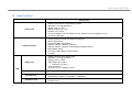
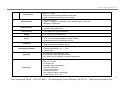


![AISER [USER MANUAL OF AISER] - Internet Banking](http://vs1.manualzilla.com/store/data/005712358_1-d8e4e34a51ac40b22276b6e3d3c9bbc0-150x150.png)