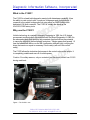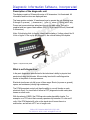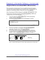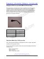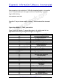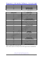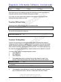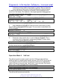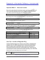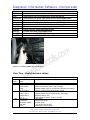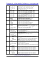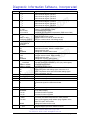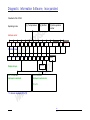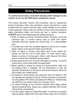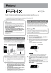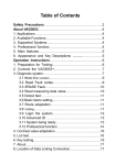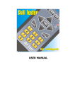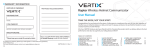
1
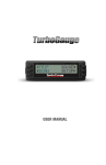
User Manual
for
C1553
VAG Diagnostic
Tester
Presented by:
DIS, Inc.
PO Box 1303
Nashua, NH 03060 USA
Tel: 603 491-1469
www.distools.com
Diagnostic Information Software, Incorporated
What is the C1553?
The C1553 is a hand held diagnostic scantool with datastream capability. It has
the ability to code control units. It works on Volkswagen and Audi products. It
connects to the vehicle’s diagnostic link using either an OBD-II cable or the
dedicated VW-Audi connector. The C1553 is virtually the same as the
VAG1551/1552 factory tools.
Why use the C1553?
Vehicle technology is constantly changing. Beginning in 1996, the U.S. federal
government required cars to be equipped with On Board Diagnostics II. OBD-II is
an advanced system that monitors any powertrain function that has the potential
to cause the vehicle to exceed tailpipe emissions. Tailpipe gases that exceed 1.5
time the federal limit will turn on the MIL (malfunction indicator light), notifying the
driver that service or repair is necessary. Fault code(s) will set in the control
unit(s).
The C1553 allows the technician fast access to the control units on the vehicle. It
is completely portable and runs off of vehicle power.
Caution: For safety reasons, only an assistant (not the driver) should use C1553
during road tests.
Figure 1. The C1553 in use.
PO Box 1303 • Nashua, NH 03061-1303 • USA
Tel: (603) 491-1469 • e-mail: [email protected]
page 1 of 1
Diagnostic Information Software, Incorporated
Description of the diagnostic unit
The display consists of 2 lines with a size of 40 characters. It is illuminated. All
information and functions are displayed here.
The lower portion contains 16 membrane keys to operate the unit. Number keys
0 through 9, up arrow ( ), down arrow ( ), plus (+), minus (-), Q-key, and C-key.
Power and communications take place through the data cable. The unit is
supplied with two types of data cables: OBD-II (16 pin) and VW/Audi (2 terminal/
2 connectors).
Note: If the display fails to display, check vehicle battery. Voltage should be 10
Volts or higher. If the unit is left plugged-in, the vehicle battery will deplete.
Figure 2. Layout of front panel
What is self-diagnostics?
In the past, diagnostics were limited to the technician’s ability to pinpoint test
each circuit using a multimeter. All cars today have built in self-diagnostics
thanks to the power of microprocessors.
Electrical circuits can only fail in one of three ways: Shorts (to power or ground),
opens, and resistance (usually high resistance).
The PCM (powertrain control unit) has the ability to run self checks on each
electrical circuit. If a circuit fails it will set a DTC (diagnostic trouble code) also
known as a fault code.
With the advent of OBD-II the PCM can also make plausibility checks. For
example: on a TPS circuit that normally operates only between 0.5 volts and 5
volts, if the PCM detected 6 volts on the signal wire it knows there is a
malfunction, and will set a DTC out of range code.
PO Box 1303 • Nashua, NH 03061-1303 • USA
Tel: (603) 491-1469 • e-mail: [email protected]
page 2 of 2
Diagnostic Information Software, Incorporated
Additionally, there are built in protection functions, which allow the engine to run
undisturbed. If there is a major fault with a circuit, the vehicle can still operate in
‘Limp Home’, ‘emergency run’, or ‘failure mode’. This allows the driver to reach a
garage for service. The basic triggering circuit is the only exception. A failed
crankshaft sensor or CKP causes the engine to stop and not restart.
Fault memory within the PCM stores DTC’s which can be accessed with the
C1553. The C1553 offers bi-directional communications with the vehicle. It can
transmit and receive data.
How does self-diagnosis work and when to use it?
All engine controls operate in a similar fashion. The PCM has inputs known as
sensors (or switches) and outputs known as control devices. The PCM makes
logical decisions based on input data. Also connected to the PCM is power and
ground. In fact, several power and ground wires are connected to the PCM.
Coolant temperature sensor or CTS (G62) is an example of an input device
operating between 0 volts and 5 volts. The sensor is an NTC or negative
temperature coefficient. As temperature goes up, resistance goes down. In an
active circuit, the voltage is high when the engine is cold and drops during warmup reaching a steady value at operating temperature. The CTS supplies
important information to the PCM for calculation of the following:
• Knock control
• Adaptation of idle speed
• Lambda control of air fuel ratio
• Control of the fuel tank ventilation
Keep in mind that the PCM also keeps track of the running time of the engine. If
the engine has been operated for several minutes the CTS voltage should
change, if not the PCM determines through self-check that a fault exists in the
CTS circuit and sets a DTC. Also, the PCM can substitute a ‘temperature’ if the
current value is not plausible.
Using the C1553, a technician can quickly check the CTS circuit by reading the
CTS datastream and comparing to the actual temperature of the coolant. Next,
disconnect the sensor. The value as reported by the C1553 should go to
approximately -40°C (-40°F). Next, with the CTS still disconnected, bridge the
two wires going to the PCM. The C1553 should now read about 120°C. A normal
substitute value for the CTS is about 70°C.
Keep in mind when diagnosing any PCM related problem that the problem may
not be the sensor that set the fault code. A CTS fault code could be caused by
faulty wiring to the sensor, a discharged battery, or loose power/ground wires to
the PCM.
PO Box 1303 • Nashua, NH 03061-1303 • USA
Tel: (603) 491-1469 • e-mail: [email protected]
page 3 of 3
Diagnostic Information Software, Incorporated
Using the C1553 on cars without OBD-II (1995 and earlier)
The tool requires no internal power. Power is supplied by the vehicle’s battery.
The cable has a polarized plug that only connects one way. Protection of the unit
depends on connecting the cable correctly and in the correct sequence.
Note: Connecting the VW/Audi diagnostic cable VAG 1551/1 and VAG 1553/1
must be done in the exact sequence given below. Connecting to OBD-II cars
(1996 and later) will be described later.
1.
2.
Connect the black plug (power supply) of the C1553 to the black flat
contact connector in the vehicle.
The following text must appear on the C1553 display to continue:
Enter address word XX
Figure 3. Display
3.
4.
5.
If the above message is not displayed, do not connect the white
connector. Damage to the C1553/vehicle will result.
As soon as the above message is displayed connect the white plug.
In cases where the message above is not displayed, check the vehicle
wiring for correct voltages at the vehicle’s connectors. See figure 4.
Black
Plug
White Plug
Figure 4. VW/Audi vehicle diagnostic connectors: Black (power/ground) and White (data).
PO Box 1303 • Nashua, NH 03061-1303 • USA
Tel: (603) 491-1469 • e-mail: [email protected]
page 4 of 4
Diagnostic Information Software, Incorporated
Black
Barrel Connector
White
Figure 5. C1553 connector views. See table for wiring assignments.
Flat connector terminals
1
2
1
2
Black A
White B
Barrel connector
3, battery ground (-)
2, battery positive (+)
4, L-line (data)
1, K-line (data)
Figure 6. C1553 cable wiring assignments.
PO Box 1303 • Nashua, NH 03061-1303 • USA
Tel: (603) 491-1469 • e-mail: [email protected]
page 5 of 5
Diagnostic Information Software, Incorporated
Using the C1553 on cars with OBD-II (1996 and later)
The tool requires no internal power. Power is supplied by the vehicle’s battery.
The OBD-II cable has a polarized plug that only connects one way. OBD-II
equipped cars have a 16 pin diagnostic connector located under the steering
column or behind a plastic trim piece in the instrument console (VW). Some
Audi’s are located in the center console. Pin 4 in the diagnostic connector is
ground; pin 16 is power at all times.
Figure 7. OBD-II connector
OBD-II
Vehicle connector terminal
4
C1553 barrel connector
7
1, K-line (data)
15
4, L-line (data)
16
2, battery (+)
3, ground (-)
Figure 8. Terminal assignments
Operation Modes the C1553 provides
Note: The modes and displays you get depend on the car, engine, equipment
installed, and the program version.
Connect the C1553 to the vehicle. After a few seconds the display will show the
following modes:
Mode 1: Test procedure
Mode 2: Self test
Mode 3: Enter work number
PO Box 1303 • Nashua, NH 03061-1303 • USA
Tel: (603) 491-1469 • e-mail: [email protected]
page 6 of 6
Diagnostic Information Software, Incorporated
After connecting to the vehicle the C1553 will automatically switch in to operation
mode 1 (Test procedure) for the engine control unit. By selecting ‘1’ you can
begin vehicle testing.
Enter address word XXX
Press the ‘C’ key to choose mode 2 or mode 3. These modes will be discussed
later.
Operation Mode 1: Test procedure
Figure 9 shows the display. To access the system in the vehicle enter the two
digit address word using the keypad. See figure 10 or figure 11.
Address Words
00
01
02
03
08
11
12
13
14
15
16
17
22
25
26
33
34
35
36
37
41
44
45
46
47
55
Vehicle system
Automatic check procedures
engine electronics
Transmission electronics
ABS electronics
air conditioning/heating
engine electronics II
clutch electronics
distance regulation
Wheel muffling electronics
Airbag/SRS
Steering wheel electronics
Combination instruments
All wheel drive electronics
theft/immobiliser
electrical roof
OBD-II generic
ride level regulation
central door locking
seat shift FL
navigation
Diesel injection pump electronics
servo-assisted steering
inner room supervision
Central module comfort system
sound system
light distance regulation
PO Box 1303 • Nashua, NH 03061-1303 • USA
Tel: (603) 491-1469 • e-mail: [email protected]
page 7 of 7
Diagnostic Information Software, Incorporated
56
66
75
76
radio
seat/mirror shift
emergency module
parking assistance
Figure 9. Address words in numerical order
Address words
08
15
22
00
03
35
46
12
41
13
26
75
01
11
17
45
55
37
33
76
56
34
36
66
44
47
16
25
02
14
Vehicle system
air conditioning/heating
Airbag/SRS
all wheel drive electronics
automatic check procedures
ABS electronics
Central door locking
central module comfort system
Clutch electronics
diesel injection pump electronics
Distance regulation
Electrical roof
Emergency module
Engine electronics
Engine electronics II
gear board stake
inner room supervision
light distance regulation
Navigation
OBD-II generic
Parking assistance
Radio
ride level regulation
Seat shift FL
Seat/mirror shift
servo-assisted steering
Sound system
steering wheel electronics
theft/immobiliser
Transmission electronics
wheel muffling electronics
Figure 10. Address words in vehicle system order
Note: Use the up/down arrow keys on the C1553 to get an index of all addresses.
PO Box 1303 • Nashua, NH 03061-1303 • USA
Tel: (603) 491-1469 • e-mail: [email protected]
page 8 of 8
Diagnostic Information Software, Incorporated
C1553 Test exercise
1. Connect the C1553 to the vehicle. The C1553 will display:
Enter address word XXX
2. Enter 00 and press ‘Q’ key. The C1553 will display:
Enter address word 00 Q
Automatic check procedure
3. By pressing the ‘Q’ key the C1553 will sends all known address words, one
after another. ECU identification will display.
4. The C1553 reads all recognized errors and displays them in sorted order.
5. The C1553 accesses all address words thereby retrieving all fault memory in
the vehicle.
6. If there are broken wires or defective devices the C1553 will not access that
ECU.
Using the C1553 to query an engine control unit
1. Turn key on or start engine. Enter ‘01’ address word. The unit displays:
Enter address word ’01 Q’
Engine electronics
2. If you press the ‘Q’ key the C1553 displays:
Send engine control address 01
3. The C1553 displays: CODE is control unit coding. WSC is Work Shop Code.
This is a code used by the VW/Audi workshop for coding replacement ECM’s.
010101010 222
CODE 1234
Engine
Q
WSC 4321
4. You can now choose functions by pressing the ‘Q’ key. The C1553 displays:
Select function XX
PO Box 1303 • Nashua, NH 03061-1303 • USA
Tel: (603) 491-1469 • e-mail: [email protected]
page 9 of 9
Diagnostic Information Software, Incorporated
5. Using the up/down arrow keys (
Functions
01
02
03
04
05
06
07
08
09
10
15
) you get an index of all functions.
ECM version
Display Fault memory
Output check
Basic settings (default settings)
Erase fault memory
End output (ends your session)
Code ECM (coding of control unit)
Measure blocks (read live value areas)
Individual blocks (read values)
Adaptation
Readiness code (USA) market
Figure 11. Function Codes
6. Typically a technician will enter 02 Q to display the fault memory, write down
the codes, then enter 05 Q to erase memory. Finish your session by entering
06 and Q.
7. If the function is not available for the control unit you are working on the
C1553 will display:
Function not feasible at this moment
Function 02 Query (display) error memory
If you selected 02, all recognized errors (fault codes) will be displayed. For
example:
7 errors recognized
Q
Press the Q key to get the details on the fault code.
Error number: 12345
Q
Press the Q key again to get message information
Power supply Kl. 30
Voltage too low
Q
Note: If ‘SP’ is displayed, the fault code is sporadic or intermittent.
PO Box 1303 • Nashua, NH 03061-1303 • USA
Tel: (603) 491-1469 • e-mail: [email protected]
page 10 of 10
Diagnostic Information Software, Incorporated
Function 03 Adjust unit diagnosis (output check)
This function allows the user to check output devices such as fuel injectors,
solenoids, valves, and motors for functionality. A multimeter is needed to
complete this test.
Function 04 Default setting (basic settings)
This function allows the user to perform basic settings (baseline settings) on
some systems after a part has been replaced or repaired.
Select 04. The C1553 will display
Default setting channel
XXX
Measured values will be displayed with the physical units
System with default setting group 20
0/min Fahrst.
EINA/C-LOW
Compr. off
To display measured values live (during engine operation) you must exit function
04 and enter function 08. To do this press the C key and enter 08. The display
will show
Read value area
XXX
Function 05 Erase error memory (erase fault memory)
As described earlier, after you know what the fault codes are, then you can erase
the error memory and road test the car to see if they come back. After you enter
05 and Q the C1553 will display
Error memory erased
If a code sets because of a vehicle problem, when you attempt to erase fault
memory the C1553 will display
Function not feasible in the moment
PO Box 1303 • Nashua, NH 03061-1303 • USA
Tel: (603) 491-1469 • e-mail: [email protected]
page 11 of 11
Diagnostic Information Software, Incorporated
Function 06 Finish output (End output)
You can finish your session (in this case with 01 engine control unit) by entering
functon 06 and Q. The C1553 returns back to the top level operating mode. Now
you can enter a new address word. You should always finish by entering 06
when done.
Function 07 Code control unit (Code ECM)
Function 07 gives the technician the ability to ‘flash’ a control unit with new
program data. Always consult the repair manual. Coding is used to ‘customize’
the control unit for a particular market or car version. Select function 07 and Q.
the C1553 will display
Code control unit
0-32000 XXXXX
The code number can be in the range from 0 to 32000, but you must enter a five
digit code. Press the Q key to confirm the code entry.
After the control unit is coded, the C1553 will display the control unit and code.
For example
01234567
ENGINE
Q
Code 1312
WSC 00000
Function 08 Read value area (Measure blocks or read live values
area)
Selecting function 08 gives the technician access to data-stream or live data from
the ECM. The lower line of the display will generally show four data-stream
parameters such as rpm, throttle position, oxygen sensor activity, and fuel trim.
Because there are so many data-stream parameters they are grouped. Each
group can be selected by the display group number and shown sequentially.
If you select function 08 the C1553 will display
Read value number
XXX
Enter the display group number and confirm by pressing Q key. The measure
values will display for example
PO Box 1303 • Nashua, NH 03061-1303 • USA
Tel: (603) 491-1469 • e-mail: [email protected]
page 12 of 12
Diagnostic Information Software, Incorporated
Read value area number 2
0/min
0.00ms
0.00ms
27.76 g/s
Since there are so many display groups the technician can scroll up or down by
using the up/down arrows to access other group numbers.
If you wish, you can access other measure value groups by pressing C then
entering the group number you wish.
Function 09 Read Value
Selecting function 09 will display only one measure value.
Read value number
XXX
Your entry must be three characters, then press Q. At any time you can delete
the current value and enter a new one.
Read value number 012
Q
Function 10 Adaptation
Function 10 should only be used by technicians who understand the results of
changing baseline settings to engine controls. For example, the base idle speed
can be changed using function 10. Changes in adaptive or baseline settings will
affect vehicle emissions, performance, and service life. The vehicle warranty may
be voided by changing these settings. Learned values can be deleted or erased.
You must follow 3 steps to change adaptation values:
1.
read adaptation
2.
test adaptation
3.
save adaptation
1.
Read adaptation value by entering the two digit channel number, then
enter Q. The ECM will transmit the currently used value for that channel
Adaptation channel
XX
For example
Adaptation channel
2.
3
value 12345
Test adaptation value allows you to modify the adaptation value. Use the +
key to increment the value. Use the - to decrement the value. Please
PO Box 1303 • Nashua, NH 03061-1303 • USA
Tel: (603) 491-1469 • e-mail: [email protected]
page 13 of 13
Diagnostic Information Software, Incorporated
confirm the running condition of the engine or system. When you have the
correct setting you want, press C then press Q and the values will saved.
If a measured value block is assigned to a channel, it will be displayed in the
lower line of the display. This depends on the engine application and equipment.
Two types of measure values can be show.
Adaptation channel 1 value
12345
0/min 0,0% 27,76g/s
Adaptation channel 2 value
134 24
34
165 13
23456
165 70
56
134
156
3.
Save adaptation is used after you have found the correct value you want.
Press the Q key, then press the Q key again. The new value is transmitted to the
ECM and saved.
Adaptation channel 02
Q
Adaptation channel 02 value
Last value
12345
XXXXX
4.
Erase learn values can be done to ‘reset’ all values to baseline. This is
sometimes useful during repair, replacement, or tuning. To erase values,
enter channel number 00 then press Q.
Adaptation channel 00
Q
Confirm channel number, and then press Q again
Erase learn values
Q
Learn value erased
Q
Operation Mode 2:
Self test
The self-test operation mode is used to test the C1553 and cable. Self-test
should be used on a regular basis to make sure the C1553 is OK. Plug in the unit
to a vehicle then enter 2 for self test. The purpose of the test is to verify that the
cable is OK and can transmit data. The ‘K’ and ‘L’ lines are tested. See figure 6
above. If the ‘K’ line is grounded the C1553 will display
K-wire does not switch to HIGH
If the ‘K’ line is shorted to power the C1553 will display
K-wire does not switch to LOW
The self-test will terminate automatically.
PO Box 1303 • Nashua, NH 03061-1303 • USA
Tel: (603) 491-1469 • e-mail: [email protected]
page 14 of 14
Diagnostic Information Software, Incorporated
Operation Mode 3:
Enter work number
Enter work number allows the technician to enter a work shop code (WSC) or id.
This is used when replacing a control unit or if adaptation values are changed.
The number is permanent and cannot be changed once entered.
Enter work number
XXXXX
Any existing work number will be displayed when you enter this mode.
Work number exists
01234
If you would like to enter a work number, press ‘3’
Enter work number
XXXXX
The work number must be 5 digits long. Pressing the C key can clear a wrong
entry. Once the right number is entered confirm your choice by pressing Q.
Enter work number
12345
Q
The following regulation must be used when entering the work number
Type of User
manufacturer of control unit (i.e. BOSCH, Siemens)
outside user (not in the company)
sales centers, importers
Volkswagen corporation
other companies
work number
00000
000XX 2-digit
00XXX 3-digit
0XXXX 4-digit
XXXXX 5-digit
User Tips - Location of Diagnostic Plug
Finding the diagnostic plug in the vehicle can seem difficult. Volkswagen/Audi
always put the 16 pin OBD-II plug in the driver’s environment-usually behind a
plastic trim piece or under the steering column. If the plug is behind a plastic
piece, the plastic will be molded with a ‘check engine’ icon. See figure 12.
Volkswagen generally puts the plug on the instrument cluster. Audi sometimes
puts the plug in the center console under the back seat ashtray cover. Most 1999
and later cars, near hood release lever in the footwell.
Pre 1995
2 pin connectors located in engine compartment at fuse box near
firewall
PO Box 1303 • Nashua, NH 03061-1303 • USA
Tel: (603) 491-1469 • e-mail: [email protected]
page 15 of 15
Diagnostic Information Software, Incorporated
Golf 3
Golf 4
Polo
Passat B4
T4
Sharan
Beetle
Audi A3
Audi A4
Audi A6
Audi A8
Audi TT
Under plastic trim piece, right of ashtray
Under plastic trim piece, above ashtray center console
Under plastic trim, left footwell area, below light switch
Under plastic trim piece, instrument cluster, behind wiper switch
Under plastic trim piece, left of radio
Under second ashtray insert piece
Footwell area near hood release lever
Center console, below storage box
Center console, below back seat ashtray
Footwell area near hood release lever
Center console, below back seat ashtray
Footwell area near hood release lever
Figure 12. Location of OBD-II plug on 1996 Passat.
User Tips – Useful measure values
Audi A4
Display
group
000
001
002
003
2.8 liter V6 OBD-II (MMS-410) 1996
Specified/Display
Designation
value
Described below
85-110°C
1=engine coolant temperature
1.450-1.580 V
2=mass air flow (MAF) sensor output voltage
0-255
3=altitude display (only on vehicles with secondary air system)
12.00-14.00 V
4=engine control module (ECM) supply voltage
0.250-4.750 V
1=throttle position sensor voltage (idle to wide open throttle)
0.250-1.275 V
2=throttle position sensor voltage at idle, lower range
0.250-0.500 V
3=learning value of TPS
0 or 1
4=mechanical TP switch, 0=open 1=closed
650-750 rpm
1=idle speed
15.0-35.0%
2=engine load at idle
0% and/or greater
3=throttle angle
than 95%
0% at idle, 95% at WOT
km/h
4=momentary vehicle speed
PO Box 1303 • Nashua, NH 03061-1303 • USA
Tel: (603) 491-1469 • e-mail: [email protected]
page 16 of 16
Diagnostic Information Software, Incorporated
004
005
006
007
008
009
010
011
0+/-2
HS:+14 to –16
AT:+10 to –20
AT: +10 to –20
001 10
-25% to +25%
-25% to +25%
-25% to +25%
-25% to +25%
-25% to +25%
-25% to +25%
-25% to +25%
-25% to +25%
0% to 6%
XXXX
XXXXXXXX
XXXXXXXX
0% to 6%
XXXX
XXXXXXXX
XXXXXXXX
…….%
…….%
0 to 99%
0% and or greater
than 95%
Difference between
display values 1
and 2 less than 8%
At times greater
than 0.6 V and/or
less than 0.V
(fluctuating display)
……..°BTDC
……..°BTDC
012
013
014
+/- _._° crankshaft
0 and/or 1
……..rpm
……..%
first map or second
map
_._° crankshaft
First may and/or
second map
_._° crankshaft
_._° crankshaft
_._° crankshaft
First map and/or
second map
_._° crankshaft
_._° crankshaft
1=idle air control valve at idle
2=idle speed learn value, HS (man.trans. +20 to –16)
AT (auto.trans. +16 to –20), lever in P or N only
3=idle speed learn value, AT lever in D,1,2,3,or R
4=shift inputs at idle, 0 off, 1 on
1=oxygen sensor learning value at idle, bank 1
2=oxygen sensor learning value at part throttle 1, bank 1
3=oxygen sensor learning value at part throttle 2, bank 1
4=oxygen sensor learning value at part throttle 3, bank 1
1=oxygen sensor learning value at idle, bank 2
2=oxygen sensor learning value at part throttle 1, bank 2
3=oxygen sensor learning value at part throttle 2, bank 2
4=oxygen sensor learning value at part throttle 3, bank 2
1=oxygen sensor control, bank 1
2=oxygen sensor learning range display
3=oxygen sensor learning requirement diagnosis
4=oxygen sensor learning requirement display
1=oxygen sensor control, bank 2
2=oxygen sensor learning range display
3=oxygen sensor learning requirement diagnosis
4=oxygen sensor learning requirement display
1=oxygen sensor control bank1
2=oxygen sensor control bank2
3=duty cycle (triggering) for EVAP canister purge regulator valve
N80
4=throttle angle, at idle 0%, at WOT >95%
1=total of oxygen sensor control bank 1 and momentary oxygen
sensor learning value bank 1
2= total of oxygen sensor control bank 2 and momentary oxygen
sensor learning value bank 2
3=Voltage signal bank 1 heated oxygen sensor 1
4=Voltage signal bank 2 heated oxygen sensor 1
1=ignition timing point without knock control and without idle
speed control
2=ignition timing point with knock control and digital idle speed
control
3=ignition timing point access to digital idle speed control
4=closed throttle position switch function. Open=0 closed=1
1=momentary engine speed
2=momentary engine load
3=ignition timing point map switching
4=ignition timing point retard by knock control-average of all cyls.
1=ignition timing point map switching
2=ignition timing point retarded by knock control, cylinder 1
3=ignition timing point retarded by knock control, cylinder 2
4=ignition timing point retarded by knock control, cylinder 3
1=ignition timing point map switching
2=ignition timing point retarded by knock control, cylinder 4
3=ignition timing point retarded by knock control, cylinder 5
PO Box 1303 • Nashua, NH 03061-1303 • USA
Tel: (603) 491-1469 • e-mail: [email protected]
page 17 of 17
Diagnostic Information Software, Incorporated
015
016
017
018
019
020
021
022
023
024
025
026
027
028
029
030
031
_._° crankshaft
rpm
_._V
_._V
_._V
rpm
_._V
_._V
_._V
0–1
0 – 255
30% to 60%
0°C to 255°C
__%
_.__A
-40% to +60%
12.000 to 14.000 V
1.5% to 3.5%at idle
6.5 to 9.5% at
2500rpm
0%
0%
69%
00000000
0.0%
0.0%
14%
00000000
0 to 12
_,_°crankshaft
-68Nm to 250Nm
-68Nm to 250Nm
X
XX
XX
X
Not used
Production use only
Production use only
X
X
Production use only
XXX XX X
XXXXXXXX
0 to 40
0 to 40
---mbar
---mbar
0 to 99%
XXXXX
…..rpm
…..rpm
4=ignition timing point retarded by knock control, cylinder 6
1=momentary engine speed
2=knock sensor signal, cylinder 1
3=knock sensor signal, cylinder 2
4=knock sensor signal, cylinder 3
1=momentary engine speed
2=knock sensor signal, cylinder 4
3=knock sensor signal, cylinder 5
4=knock sensor signal, cylinder 6
1=timer 1 (final value=1)
2=timer 2 (final value=48 or 160)
3=momentary engine load
4=exhaust gas recirculation temperature (EGR sensor G98)
1=internal duty cycle, idle air control valve N71
2=idle air control valve current
3=power control from idle air control valve N71
4=engine control module J192 voltage supply
1=momentary engine power (internally computed)
1=lean time of bank 1, HO2S 1 voltage signal
2=lean time of bank 2, HO2S 1 voltage signal
3=diagnosis limit value
4=diagnosis condition and/or result
1=oxygen sensor control, bank 1 richens
2=oxygen sensor control, bank 2 richens
3=diagnosis limit value
4=diagnosis condition and/or result
1=reducing stages
2=ignition timing point retarded by ATC (only cold engines)
3=reduced engine torque
4=unreduced engine torque
1=upshift signal, auto trans. 01V. comes from TCM
2=gear recognition and shifting signal, auto trans. 01V.
3=A/C compressor off/on and rear window heating signal
4=A/C compressor shut off
Not used
Production use only
Production use only
1=malfunction indicator lamp from TCM
2=Fuel level signal from instrument cluster
3=
4=
Production use only
1=Readiness code status, see notes
2=Trip status display
3=counter for warm up phase
4=counter for warm up phase
1=currently measured evap system under pressure
2=currently calculated evap minimum under pressure
3=duty cycle triggering evap canister purge regulator valve,
where 0%=open, 99%=closed
4=diagnosis status and/or result
1=lowest engine rpm when misfired occurred
2=highest engine rpm when misfired occurred
PO Box 1303 • Nashua, NH 03061-1303 • USA
Tel: (603) 491-1469 • e-mail: [email protected]
page 18 of 18
Diagnostic Information Software, Incorporated
__.__%
3=lowest engine load when misfired occurred
__.__%
4=highest engine load when misfired occurred
Notes: bank 1 is defined as the side of the engine where cylinder #1 is located. Sensor 1 is
upstream of catalytic converter, sensor 2 is downstream.
Knock control of timing depends on fuel octane, worn/loose engine components, engine damage.
029-readiness code is required under OBD-II regulations. When set (=1) it shows that every
component or system that affects exhaust emissions (capable of turning on MIL) has been
operated with positive results. If a DTC is set (MIL on) the readiness code is erased. The
following will erase the readiness code: battery disconnected, ECM disconnected. To generate a
readiness code you must take a mixed city/highway trip: 1.5 to 5 minutes at 80 to 100kph. Display
field 1 should set to all zeros (0). Display field 1: XXX XX X the address bits are decoded as
follows starting from the right most digit: 3-way catalytic converter, not used, evaporative
emissions throughput, secondary air system and throughput, not used, heated oxygen sensor
problems, oxygen sensor heating problems, EGR.
PO Box 1303 • Nashua, NH 03061-1303 • USA
Tel: (603) 491-1469 • e-mail: [email protected]
page 19 of 19
Diagnostic Information Software, Incorporated
Volkswagen 2.8 liter VR6 1995
Code
Meaning
Continue troubleshooting using wiring diagrams
No
DTC
recogn
ized
00281
00513
00515
00518
00522
00524
00525
00527
00532
00533
00535
00537
00540
00543
00545
00549
00553
00561
00585
00586
00609
00610
00611
00640
01025
01235
01242
01247
01249
01250
01251
01252
01253
01254
01257
01259
01264
01265
65535
1231
2111
2113
2212
2312
2142
2342
2412
2234
2231
2141
2341
2144
2214
2314
2243
2324
2413
2411
3434
4313
4332
4343
4411
4412
4413
4414
4421
4422
4431
4433
4311
4312
1111
Vehicle speed sensor G68, no signal
Engine speed sensor G28, no signal
Camshaft position sensor G40
Throttle position sensor G69
Engine coolant temp sensor G62
Knock sensor 1 G61
Heated oxygen sensor G39
Intake air temp sensor G72
Battery voltage higher than 16.0 volts
Idle speed actuator
First knock control
Oxygen sensor control, limit exceeded or not reached
Knock sensor 2 G66
Maximum engine speed exceeded
Engine/transmission electrical connection
Fuel consumption signal
Mass air flow sensor G70
Mixture adaptation limit exceeded or not reached
EGR temp sensor G98
EGR system regulation
Ignition output 1
Ignition output 2
Ignition output 3
Heated Oxygen sensor relay J278
MIL lamp activation faulty
Secondary Air Injection solenoid valve N112
Engine control module output stage
EVAP canister purge regulator valve 1 N80
Fuel injector cylinder 1 N30
Fuel injector cylinder 2 N31
Fuel injector cylinder 3 N32
Fuel injector cylinder 4 N33
Fuel injector cylinder 5 N83
Fuel injector cylinder 6 N84
Idle air control valve N71
Fuel pump relay J17
Secondary air injection pump relay J299
EGR valve N18
Engine control module faulty
PO Box 1303 • Nashua, NH 03061-1303 • USA
Tel: (603) 491-1469 • e-mail: [email protected]
page 20 of 20
Diagnostic Information Software, Incorporated
Flowchart of the C1553
(1) Test procedure
Operating mode
(2) Selftest
(3) Enter operation
number
Address words
00
01
03
08
11
12
13
14
15
16
04
05
06
07
08
09
15
17
22 - 26
Function Codes
01
02
03
See note*
Display Groups
9 or 10 channels
displayed in decimals
future
4 or 5 channels
displayed in actual units
01 to 15
*=1 channel displayed (00 to 15)
PO Box 1303 • Nashua, NH 03061-1303 • USA
Tel: (603) 491-1469 • e-mail: [email protected]
page 21 of 21
33
34 - 76