Transcript
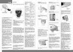
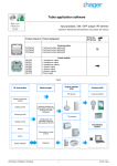
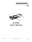
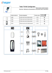
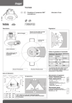
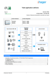
Technical characteristics
GB
TG 053
Supply voltage
24 V DC or 20 V AC
Weather station KNX
Consumption
max. 100mA,
Residual undulation
10%
6T 7343.a
N
tebis
TP
RF
20V AC
24V DC
Bus
30 V
/
GB
All control events, time programs, and the 8
logical inputs (such as communication objects)
can be used as inputs of logical gates.
The output of each gate can be configured in
1-bit or 2 x 8-bit format.
The KNX is configured using the ETS software.
In version ETS 3 and higher, the settings
menus of the TG 053 feature an optimal
graphical presentation.
Working temperature
-30°C to + 50°C
vertical
post
Half-crescent
facing
The weather station must be installed on a wall
or a vertical post.
Protection class
IP44
Dimensions
96 mm x 77 mm
x 118 mm (lxLx h)
Weight
~146g
Heating
The weather station TG 053 measures the
outdoor temperature, the wind speed and light.
It detects rain and daylight fall, and receives
date and time by radio signal DCF77.
Moreover, it calculates the exact position of
the sun (azimuth and elevation) using the site
coordinates, the date and the time.
The weather station TG 053 includes an annual
clock and a weekly clock. The clock channels
can switch the outputs using the communication objects.
The weekly clock controls up to four different
time settings for each day of the week.
The annual clock can be used to define up
to three periods in the year with two daily
ON/OFF commands for each of them.
The switching times can be defined by settings
or the communication objects.
The weather station also has 8 logical AND
gates and 8 logical OR gates, each with four
inputs.
EIB/KNX
+/- plug-in bus
terminal
or
Installation on a post: apply the curved side of the
support on the post with the half-crescent facing
downwards.
Preparing the weather station
Cover
with
rain sensor
1,2 Watt (24 V)
Make sure that the weather station is horizontal.
Clicking the
cover into
place
Plate
Lower part
of the unit
Temperature sensor:
Measurement range
-40°C to +80°C
Resolution
0.1°C
Installing the support
The weather station TG 053 includes a support
for installation on a wall or a vertical post.
The support is clipped to the rear of the unit.
Wind sensor:
Legend:
1- Connector for the rain sensor cable built into the
cover of the unit.
2- Spring-loaded terminals for the 24 V DC/20 V AC
power supply for rigid conductors measuring up
to 1,5 mm² or for flexible conductors.
3- Opening for the power supply cord.
4- Opening for the KNX bus cable.
5- Position of the KNX connector (+/-).
6- Physical address button.
7- Physical address LED.
8- Adjusting screw for the DCF77 antenna.
9- DCF77 reception light.
Measurement range
0 m/s to 70 m/s
Precision
< 10% of the
measure value
Light sensor:
Measurement range
0 Lux to 150.000 Lux
Precision
+/- 10% of the
measure value
Two articulated supports are available as
option (TG 353 and TG 354) for wall mounting,
on post or beam.
Detach the support by unscrewing with a
screwdriver.
The screws retaining the support are located
on the left and right as shown in the diagram.
Positioning the DCF77 antenna
The antenna that receives the DCF77 signal for the
date and time is in the unit, under the electronic
board.
The adjusting screw (see legend num. 8) can be
used to move the antenna through 180° and to
position it. Reception is OK when the DCF77
reception light (see legend num. 9) flashes in a
regular manner once a second (the light stops
flashing after 59 seconds).
The light can be prevented from flashing in the ETS
software.
Never start up a weather station that shows
signs of damage.
If use without danger is not possible, switch off the
system and protect it against an accidental restart.
The weather station must be used as a fixed
system. It must only be started after all the
installation works have been completed and in an
environment designed for this purpose.
Hager refuses any liability for possible changes to
standards that may be made after the publication
of these instructions.
Location
Select a clear site that allows for
correct measurements by the wind,
rain and sun sensors.
South direction is advised for correct
measurement of brightness level.
The weather station must never be installed
beneath structures from which water may
fall onto the rain sensor after the end of the
precipitations (rain or snow).
The weather station must never be placed in
the shadow of a building or trees.
Arrange a space of at least 60 cm under
the weather station to allow for correct wind
measurements and to prevent snow from
covering the sensor.
The presence of metal structures or large
sheet metal pieces behind or near the
weather station will affect the quality of
reception of the DFC77 radio clock.
Please allow for this when installing the
TG 053.
Other factors may also interfere with or affect
the reception of the DCF77 signal, such as
magnetic fields, transmitters or radioelectrical
interference from fluorescent light tubes,
illuminated signs, power supplies with
switches, etc.
Installing the weather station
Close the unit by raising the cover on the lower
part. The cover is clipped onto the lower part on
the left and right. A "click" can be heard.
Unclip the support by pushing it downwards.
Attach the support vertically on a wall or a
post.
Half-crescent
facing
Lock
mechanism
Installation on a wall:
Apply the flat side of the support against the
wall with the half-crescent facing upwards.
1
6T 7343.a
The cover of the weather station is clipped to the
lower edge of the unit on the left and right.
Remove the cover of the weather station.
Proceed with care to avoid detaching the cable
between the rain sensor built into the cover and
the electronic circuit board.
Pass the power cables and the KNX bus through
the rubber seals on the lower part of the weather
station, then connect the L/N power cables and
the KNX bus (+/-) to the terminals provided.
Installation and startup
Only qualified technicians must install, check, start
up and repair the appliance. Make a note of all the
lines to be installed with the appliance switched off
and protect them against risks of being powered
up.
The weather station is designed only for the uses
described in this user manual. Any non-compliant
changes or breaches of the specifications in this
user manual will render the warranty null and void.
Check that the appliance is complete and in perfect
condition (no mechanical damage) immediately
after unpacking it.
If damage has occurred during transportation,
inform the supplier immediately.
Slide the top of the unit onto the previously
installed support.
The pins on the support are clipped in the rails
of the unit.
Remove the weather station by pulling the unit
upwards until it is unclipped from the support.
Unclip the support and
pull it upwards
Rain sensor:
Presentation
The compact TG 053 unit houses the sensors,
data processing electronics and the connection with the KNX bus.
The values measured are sent to the KNX bus
as physical values (2x8 bits ou 1 bit).
The position of the sun is calculated using the
date, time and the settings downloaded in the
appliance (site coordinates) and may then be
sent on the KNX bus.
Each output has communication objects
indicating the measured and calculated values.
The state of outputs depends on one or more
levels.
Thresholds can be defined by settings or the
communication objects.
Bus connection
Wall
Check that the cover and the lower part are clipped
into place.
The illustration shows the closed weather station,
seen from below.
2
Recommendations for installation
Do not open the weather station, otherwise
rain water may enter the unit.
Just a few drops of water can damage the
electronics.
Make sure that the connections are correct.
Poor connections can destroy the weather
station or any connected electronic appliances.
When installing the weather station, make
sure that the temperature sensor (the small
plate in the lower part of the unit) is not
damaged. Take care not to damage the cable
between the electronic board and the rain
sensor by pulling or bending it.
The wind speed measurements and the
associated switch outputs only start working
60 seconds after the station is switched on.
Maintenance
Regularly (at least twice a year) check that the
weather station is clean and clean it if necessary.
Severe soiling can affect the operation of the
wind sensor, provoke permanent rain signals
or inhibit the sun detection function.
For safety reasons, switch off the
mains power supply before servicing
or cleaning the weather station (switch
off the circuit breaker).
Transmission protocol
The use of chopped power supplies can affect
the quality of reception of the DCF77 radio
clock.
The DCF77 signal is subject to interference.
It is possible that no DCF77 radio signal is
received for long periods.
The time from the DCF77 clock must therefore
only be used for synchronisation purposes
with a clock operating on the KNX bus.
Preferably use second 0.
The EMC tests of the appliance were conducted
according to the following standards:
Radioelectric interference:
EN 60730-1:2000 Partie CEM (23, 26, H23, H26)
(threshold value: B)
EN 50090-2-2:1996-11 + A1:2002-01
(threshold value: B)
EN 61000-6-3:2001 (threshold value: B)
Immunity to radioelectric interference:
EN 60730-1:2000 Partie CEM (23, 26, H23, H26)
EN 50090-2-2:1996-11 + A1:2002-01
EN 61000-6-1:2004
The conformity of the product with the standards
listed above has been tested by an accredited
EMC laboratory.
6T 7343.a