1
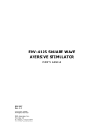
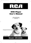
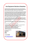
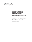
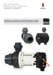
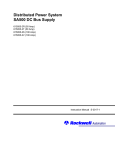
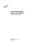
DC Output Module
DCR600-20
6,000W
0-600 Vdc / 0-20Adc
Three Phase AC Input
Requires AMX AC Power Source
Standard Features:
•
Wide Useable Range
Up to 600Vdc Voltage and 20Adc Current Output
•
Three Phase AC Input
Requires Programmable AC Power Source with
Square Wave Capability
•
Adds DC capability to AC Power Source
DC Output Voltage Derived from Provided AC RMS
Input Voltage
•
Program DC Transients Using UPC Controller
Functions
Run Dynamic Voltage Tests on DC Powered
Equipment
•
Dual Banana Jacks Provided on Front and Rear Panel
Easy Connection of DMM or Scope to Monitor DC
Output Voltage
•
Circuit Breaker on Front Panel
Quick AC Input Power Disconnect Removes DCR Unit
from AC Source Output
•
19” Rack Mount Enclosure with Removable Rack Ears
Fits easily on Lab Bench, on Top of the AC Power
Source Used or in Instrument Cabinet
Available Options:
DCR600-20 DC Output Module
The DCR600-20 is a unique approach to generating programmable DC voltages to test
DC powered equipment using a Pacific Power Source AMX Series AC Power Source.
The DCR600-20 connects between the AC Power Source outputs terminals and the
UUT and rectifies the programmed AC output voltage into a stable DC voltage.
Pacific Power’s AMX-Series high performance Linear AC Power Sources offer low
output voltage noise and distortion, ease of installation, and high AC waveform
fidelity that is used to produce the required DC output voltage.
DC Test Capability From an AC Power Source
Leverage your existing investment in your AC Power Source by using it not only
for AC product development and test but for DC power products as well. The
same programmable features and function available on the AC Power Source
can be applied to an AC derived DC output. DC voltage is twice that of the AC
Line to Neutral voltage so scaling from AC to DC is easy.
Simple Connection, Quiet Operation
The DCR unit is placed between the AC Power Source output and the DC load
under test. For best results, a three phase AC Power Source is recommended. No
other equipment is needed to provide DC power. A set of banana jacks is provided on the DCR unit to connect a DMM which can be used to monitor the DC
output voltage. No DC bias supply is needed to operate the DCR unit and only
convection cooling is needed to cool the unit so no fan noise is present.
DC Test Sequence Programming
•
UPC Studio Software Suite (available at no cost)
•
UPC Test Manager
UPC Manager Software Suite
By programming the required AC voltage output sequence on the AC Power
Source, sophisticated test sequences can easily be applied to a DC unit under
test.
Master the Power of the Wave!
The Leader in AC Power Technology now offers DC
UPC Manager Software
gives you the tools necessary to quickly and easily
operate your DC output
unit through the AC Power
Source. This Windows software supports controls over
all areas of your Power control all areas of your Power
Source testing with simple
presets, user prompts, test
sequences, test plans and
custom reports
An early pioneer in the development solid-state power conversion equipment,
Pacific Power Source continues to develop, manufacture, and market both linear
and high-performance PWM AC Power Sources. Pacific’s reputation as a market and
technology leader is best demonstrated by its continuing investments in both research and development and world-wide customer support. With corporate owned
offices in the United States, Germany, the United Kingdom, and China, local personalized support is always available.
FREQUENCY CONVERSION
THE POWER OF EXPERTISE
AEROSPACE
R&D
MILITARY
MANUFACTURING
CUSTOM
DCR600-20
Specifications: DC Output
DC Output
Parameter
Specification
Unit
Conditions
DC
600
Vdc
Maximum allowable DC Output Voltage
Accuracy
±1.0
% Range
Rise Time
< 2.0
msec
0-100% voltage change @ 10-90% amplitude at 300V/20A load
< 4.0
msec
0-100% voltage change @ 10-90% amplitude at 600V/ 10A load
< 15.0
msec
100-0% voltage change @ 90-10% amplitude at 300V/20A load
< 40.0
msec
100-0% voltage change @ 90-10% amplitude at 600/10A load
DC Ripple RMS
< 750
mV RMS
See Note 2
DC Ripple pk-pk
< 4.0
V peak-peak
See Note 2
Load Regulation
< 0.5
% of full range
With CSC on and UPC32 and external sense at DCR input. AMX in
Direct coupled mode on 135Vac range
< 1.5
% of full range
With CSC on and UPC32 and external sense at DCR input. AMX in
Transformer coupled mode on 270Vac range
20
Adc
Voltage
Fall Time
Current
Max.
Current Limit
-
See Note 1
Maximum supported DC Output Current
Determined by AC Power Source Programmable Current limit setting.
Power
Max.
6000
Watts
Other
Output
Capacitance
470
μF
Controls
DC Output
None
See voltage and current rating chart below
NOTE: No DC Output disconnect is provided. A contactor or disconnect switch may be added between DC terminal block and UUT if
desired
NOTES:
1. Applies under nominal load with transfer function Vac = (Vdc + 1.4) / 2.02 where Vdc is the desired DC output voltage and Vac is the programmed
AC voltage.
2. Specifications shown apply when using AMX AC Power Source model in three phase output mode (FORM3) and standard square wave output
waveform at 400Hz fundamental.
Input Power Requirements
AC Input
Parameter
Voltage
Specification
Unit
VAC RMS (L-N)
0-300
Vac RMS
Maximum allowable AC RMS Input Voltage.
VAC Peak (L-N)
300
Vpeak
Maximum allowable AC Peak Input Voltage
3
3 Phase + Neutral
FORM
Waveform
Square Wave
Frequency
400
Hz
Current
Max.
30
A/phase
Power
Max.
6000
Watts
Controls
AC Input Breaker
Terminals
AC Input
Input Safety Cover
Included
See Note 3
Recommended AC Source Output Setting
3 Pole, 30 Arms
Rear Panel
Conditions
Recommended AC Source Output Setting
Input Circuit Breaker Protection
See voltage and current rating chart below
Front Panel mounted
Terminal Block
3 Wires + Ground.
Protects against accidental touching of AC input
NOTES:
3. DCR600 Unit is operable with single phase AC input but AC to DC Scaling will be lower and Ripple higher. For best performance, three phase AC input is recommended. All data shown is for three phase AC input.
DCR600-20
DC Output Power Rating Curve
Rated Continuous Load Current as a Function of Output Voltage
Chart shown assumes AC Power Source model used is capable of supplying the required AC current as demanded by the DC
load on DCR output at the programmed voltage. Check relevant Pacific Power Source AC Model data sheet for AC voltage
and current rating charts.
MODEL
VA
Vrange
Coupling
Direct
305AMXT
500
750
2000
4500
6000
135
DC Curr.
(Adc)
Power
125
1.50
14
1.30
250
2.2
551
28
1.9
55
1.00
375
1.5
550
2.0:1
270
250
0.75
502
1.1
551
2.5:1
338
299
0.60
600
0.9
527
135
125
2.00
250
2.9
735
14
1.40
28
2.1
59
1.5:1
202
187
1.30
375
1.9
715
2.0:1
270
250
1.00
502
1.5
735
2.5:1
338
299
0.80
600
1.2
703
135
125
6.00
250
8.8
2205
14
3.6
28
5.4
151
1.5:1
202
187
4.00
375
5.9
2200
2.0:1
270
250
3.00
502
4.4
2205
2.5:1
338
299
2.40
600
3.5
2110
135
125
12.00
250
17.6
4410
14
7.0
28
10.5
295
1.5:1
202
187
8.00
375
11.7
4399
2.0:1
270
250
6.00
502
8.8
4410
2.5:1
338
299
4.8
600
7.0
4219
135
125
13.6
250
20.0
4998
14
9.0
28
13.5
378
1.5:1
202
187
10.70
375
15.7
5884
2.0:1
270
250
8.00
502
11.7
5880
2.5:1
338
299
6.40
600
9.4
5626
Direct
360AMXT
Vdc
187
Direct
345AMXT
Available
Arms
/Phs @ Vset
202
Direct
320AMXT
Vset
(AC)
1.5:1
Direct
308AMXT
Vmax LN
All Data shown for 3 Phase Mode (FORM3)
Avionics DC Test Sotware Options
Owners of the DCR option may use the growing library of Avionics Compliance Test Sequence Software to perform DC
Power Group testing at either 28Vdc, 135Vdc or 270Vdc. The DC Test Sequence are included in the Avionics Test Options
available from Pacific Power Source for use with its UPC Studio Test Manager Windows Software. The table below shows
currently supported test standards. Contact Pacific Power Source to check on availability of DC test sequences.
Manufacturer / Organization
Test Standard
Airframe
Revision
PPS Part Number
Airbus Industries, Europe
ABD0100.1.8
A380
E
149102
Airbus Industries, Europe
ABD0100.1.8.1
A350
C
149125
Boeing, USA
787B3
787 Dreamliner
C
149126
Radio Technical Commission for Aeronautics
(RTCA)
DO160, Section 16 Commercial Aviation
G
149124
US Department of Defense (DoD)
MIL-STD-704
F
149101
Military Aviation
DCR600-20
Principle of Operation
The DCR600-20 uses a three phase diode bridge to rectify the AC input voltage to a single DC rail. By using the square wave
capability of the AMX Series AC Power Sources, low voltage ripple can be accomplished with only minimal bulk DC storage
capacitance at the output. This results in faster DC slew rates compared to a typical 6KW DC Power Supply. No modifications
are needed to the AC Power Source to use the DCR unit as it is fully self-contained. If the DCR unit is placed away from the
AC Power Source used to drive its input, it is recommended to use the external voltage sense capability of the AC Power
Source to minimize line losses1.
A block diagram of the DCR unit is shown in the figure below for reference.
Applications
The DCR is most practical for higher Voltage DC applications (100Vdc to 600Vdc) as these ranges are a better fit for the 135V
or 270VAC voltage ranges of the AC power source. Lower voltage settings will generally provide only little DC output power
as the AC Power Source does not deliver higher current at lower voltages. Check the Voltage and Current rating chart of the
AC Power Source model you plan to use to drive the AC input side of the DCR unit.
Applications for DC testing are numerous and only a handful of typical examples are listed here.
•
•
•
•
LED Lighting
Power Conversion, Power Factor Correction
DC Motors and Actuators
DC Power Distribution in Avionics
DC Output Samples
The waveform capture screens shown below represent typical DC output voltages resulting from using the
DCR600-20 with a 345AMX AC Power Source. All data is taken using the recommended AC output parameters
of 400Hz, Square wave and FORM3 AC output mode.
AC Input and DC Output Waveforms
This scope screen image shows three phase square
wave from and the resulting DC Voltage and Current
waveforms into the load.
Note: No External DC Voltage Sense capability is provided so the distance between the DC load and the DCR unit should be kept to a minimum with sufficiently sized load wire gauge.
1
DCR600-20
Programmed DC Voltage Ramp
This scope screen image shows the DV voltage ramping from
0Vdc to 270Vdc using a slew rate of 54Vdc/sec over a 5 second
period.
Programmed DC Voltage Dip
This scope screen image shows the result of a programmed
DC voltage drop to 0Vdc for 100 msec under light load conditions. The downward slope is caused by the RC constant of the
DCR600 output capacitance.
Typical Peak to Peak Voltage Ripple
This scope screen image shows a magnified vertical view of the
DC output voltage which illustrates the relatively low Vdc peak
to peak ripple present on the output.
Indirect Control of DC Power- Simple, Intuitive Operation
The UPC Controller part of the AMX Series of Programmable AC Power Sources. When used with the DCR unit, AC
voltage amplitudes are scaled to a DC voltage output. The
scaling factor depends on the number of AC output phases
(1 or 3) and the shape of the AC waveform selected.
4 x 16 Character LCD
Display
Parameter Control
For best results, a three phase output and Square waveform is
recommended.
Using the front panel keyboard and display, all controller
models provide for selection of power source output mode,
coupling, voltage, and frequency.
Both the UPC-1 and UPC-32Controllers are available with
either RS-232 or GPIB remote interface. Commands are
structured in accordance with SCPI (Standard Commands for
Programmable Instruments).
Program Edit and Function Key
Output Control, Slew, and enable Keys
DCR600-20
16.75" (425mm)
19" (483mm)
2U
3.5”,
89mm)
DCR600-20 DC Output Module
Mechanical Specifications
General/Environmental
Ambient Temperature
Operating: 0° - 50° C
Storage: -20 ° - 80° C
Chassis Type
Protection and Safety
Output Bleeder
Weight Net: 12.6 lbs / 5.7 Kg
Shipping: 20 lbs / 9 Kg
Cabinet Mount
Internal, 50KOhm Across DC Output, Heat Sink Mounted.
Bleed Resistor
IEC61010
EMC
IEC61326
Terminals
CE Mark Pending
Marking
Removable Rack Ears. Requires L Brackets or Slides.
Rack Slide Mounting Holes on Side of Chassis. Contact
Customer Service for Rack Slide Option.
Regulatory Compliance
Safety
2U Rack Height
Dimension 16.75” x 3.5” x 9.6”
( W x H x D) 425 x 89 x 245 mm
Width includes Rack Ears: 19” / 483 mm
Depth includes Safety Covers: 11.5” / 292 mm
On / Off Circuit Breaker Use AC Breaker to Disconnect DC Rectifier from AC Source
Output.
Isolation Output to chassis 1200 Vdc / 1600 Vac
Input to chassis
1350 Vac
19” Rack Mount
Input
5 Pole Terminal
Compression Block
Phase A, B, C,
Neutral
Chassis Ground
Output
3 Pole Terminal
Block
Rated to 600Vdc,
85Adc.
DC Pos, DC Neg.
Ground Stud near
DC output terminal
to allow ground
EUT as needed
Ground
AC Input Terminal
Connection Block &
Ground stud on
Rear Panel
Options
Hardware
RMS
Rack Mount Slide Kit.
Software
UPC
Manager
Windows Control Software. Controls Steady
State Settings, Measurements and Output
Sequence Programming
UPC Test
Manager
Comprehensive Test Planner and Test
Sequence Management Software. Requires
UPC Manager program.
DC Test
Options
Mil-Std704, RTCA/DO160 ,Airbus, Boeing
Cooling Convection
Front Panel Controls On/Off
/ Indicators switch
Banana
Jacks
Rear Panel Terminal
Connections / Blocks
Indicators Safety
Covers
Provided
Banana
Jacks
Circuit Breaker
Use AC breaker
to disconnect DC
Rectifier output
from AC Source
Output.
Dual Safety type, 4mm, Sheathed
Female 19 mm Spacing
Red for +DC
Black for -DC
AC Input Connections, 4 Wire + Ground
DC Output Connections
AC Input Terminal Block
DC Output Terminal Block
Dual Safety type, 4mm, Sheathed Female. 19 mm Spacing.
Red for +DC
Black for -DC
Ordering Information
Model
DRC600-20
Controller
Requirements
N/A
Requires AMX Series Programmable AC Power Source
Order Example
Typical Delivery Items
DRC600-20
•
DC Rectifier Chassis
Ship Kit:
•
User Manual on CD ROM
•
Input and Output Safety Covers
Available Models
DCR600-20
17692 Fitch, Irvine, CA 92614 USA
Phone: +1 949.251.1800
Fax: +1 949.756.0756
Toll Free: 800.854.2433
E-mail: [email protected]
www.pacificpower.com
© 2013 Pacific Power Source, Inc. Subject to change without notice.
#6DSDCR600-20 Rev 1215