1
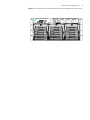
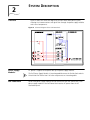
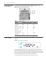
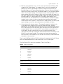
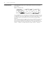
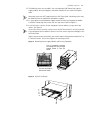
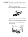
3Com® Switch 8800
Power Over Ethernet
Installation Guide
www.3Com.com
Part Number: 10015270 Rev. AA
Published: July 2006
3Com Corporation
350 Campus Drive
Marlborough, MA
USA 01752-3064
Copyright © 2006, 3Com Corporation. All rights reserved. No part of this documentation may be reproduced in any form or
by any means or used to make any derivative work (such as translation, transformation, or adaptation) without written
permission from 3Com Corporation.
3Com Corporation reserves the right to revise this documentation and to make changes in content from time to time
without obligation on the part of 3Com Corporation to provide notification of such revision or change.
3Com Corporation provides this documentation without warranty, term, or condition of any kind, either implied or
expressed, including, but not limited to, the implied warranties, terms or conditions of merchantability, satisfactory quality,
and fitness for a particular purpose. 3Com may make improvements or changes in the product(s) and/or the program(s)
described in this documentation at any time.
If there is any software on removable media described in this documentation, it is furnished under a license agreement
included with the product as a separate document, in the hard copy documentation, or on the removable media in a
directory file named LICENSE.TXT or !LICENSE.TXT. If you are unable to locate a copy, please contact 3Com and a copy will
be provided to you.
UNITED STATES GOVERNMENT LEGEND
If you are a United States government agency, then this documentation and the software described herein are provided to
you subject to the following:
All technical data and computer software are commercial in nature and developed solely at private expense. Software is
delivered as “Commercial Computer Software” as defined in DFARS 252.227-7014 (June 1995) or as a “commercial item”
as defined in FAR 2.101(a) and as such is provided with only such rights as are provided in 3Com’s standard commercial
license for the Software. Technical data is provided with limited rights only as provided in DFAR 252.227-7015 (Nov 1995) or
FAR 52.227-14 (June 1987), whichever is applicable. You agree not to remove or deface any portion of any legend provided
on any licensed program or documentation contained in, or delivered to you in conjunction with, this User Guide.
Unless otherwise indicated, 3Com registered trademarks are registered in the United States and may or may not be registered
in other countries.
3Com and the 3Com logo are registered trademarks of 3Com Corporation.
Cisco is a registered trademark of Cisco Systems, Inc.
Funk RADIUS is a registered trademark of Funk Software, Inc.
Aegis is a registered trademark of Aegis Group PLC.
Intel and Pentium are registered trademarks of Intel Corporation. Microsoft, MS-DOS, Windows, and Windows NT are
registered trademarks of Microsoft Corporation. Novell and NetWare are registered trademarks of Novell, Inc. UNIX is a
registered trademark in the United States and other countries, licensed exclusively through X/Open Company, Ltd.
IEEE and 802 are registered trademarks of the Institute of Electrical and Electronics Engineers, Inc.
All other company and product names may be trademarks of the respective companies with which they are associated.
ENVIRONMENTAL STATEMENT
It is the policy of 3Com Corporation to be environmentally-friendly in all operations. To uphold our policy, we are committed
to:
Establishing environmental performance standards that comply with national legislation and regulations.
Conserving energy, materials and natural resources in all operations.
Reducing the waste generated by all operations. Ensuring that all waste conforms to recognized environmental standards.
Maximizing the recyclable and reusable content of all products.
Ensuring that all products can be recycled, reused and disposed of safely.
Ensuring that all products are labelled according to recognized environmental standards.
Improving our environmental record on a continual basis.
End of Life Statement
3Com processes allow for the recovery, reclamation and safe disposal of all end-of-life electronic components.
Regulated Materials Statement
3Com products do not contain any hazardous or ozone-depleting material.
Environmental Statement about the Documentation
The documentation for this product is printed on paper that comes from sustainable, managed forests; it is fully
biodegradable and recyclable, and is completely chlorine-free. The varnish is environmentally-friendly, and the inks are
vegetable-based with a low heavy-metal content.
CONTENTS
CONTENTS
1
INTRODUCTION
Switch 8800 PoE Power Rack 5
Features 5
Architecture and Configurations 5
2
SYSTEM DESCRIPTION
Overview 9
Power Supply Modules 9
PoE Power Rack 9
Power Supply Module Visual indicators
System Controller 10
Distribution Panel 12
3
10
SAFETY
Safety Statements 13
Warning Statements and Safety Symbols
Precautions 13
4
INSTALLATION AND TESTING
Introduction 15
Guidelines 15
EMI Considerations 15
Safety 15
Installation Sequence 15
Install the PoE DIMM Module 16
Technical Specifications 16
Install the PoE DIMM Module 16
Mount Chassis 16
Install Power Supply Modules 18
Ground PoE Power Rack 18
Connecting to AC utility/ AC grounding
Initial Start-up 19
Powering on the Device 19
5
13
19
ENGINEERING, MAINTENANCE AND TROUBLESHOOTING
Maintenance and Troubleshooting
LED Indication 21
21
3
4
CONTENTS
1
INTRODUCTION
Switch 8800 PoE
Power Rack
The 3Com Switch 8800 PoE power rack is a modular, stand-alone Power over
Ethernet (PoE) power source. The PoE Power Rack provides a total of 4500 Watts of
DC power with 2+1 power redundancy for PoE powered devices connected to the
Switch 8800 chassis.
Features
The PoE Power Rack has the following features:
Architecture and
Configurations
■
Compatible with a wide range of input voltages from 90 V to 264 V and uses 20
A/250 VAC EN60320 C20 appliance coupler connectors and connector plugs.
■
Power factor is above 0.99
■
Efficiency is over 88%
■
Maximum device output is (N + 1) 90A @ 54V
■
Power supply modules are hot-swappable for uninterrupted operation
■
The PoE Power Rack power status may be monitored by an RS232 or RS485
interface
■
Advanced EMC (Electro Magnetic Compatibility) design
■
High safety and reliability
The PoE Power Rack architecture integrates DC power supply modules (3 maximum),
a system controller, and the distribution module, in a four rack-unit-high (4U) chassis.
The system controller provides local monitoring and control of the device. The general
configuration is shown in Table 1.
Table 1 The PoE Power Rack Configuration
Description
Standard Configuration
4U high chassis
D x W x H- 320.5 x 482.6 x 177mm (12.62 x 19.00 x 6.97 in)
System controller
One
SWITCH 8800 PoE
Power Supply Module
One installed (3 maximum for power redundancy)
AC distribution
components
■
Three independent AC power input sockets with three AC Power
switches
■
3-phase AC voltage sensor
The standard PoE Power Rack is configured with one power supply module. The
power rack may be configured with up to 3 power supplies based on the power and
power redundancy requirements. Refer to Figure 1 for overall dimensions. Refer to
Figure 2 for the rear view of the PoE power rack.
6
CHAPTER 1: INTRODUCTION
Figure 1 The PoE Power Rack
Figure 2 The PoE Power Rack (Rear View)
Refer to Figure 3 for the front view of a fully equipped PoE power rack. It consists of:
■
System controller with 2 LEDs and 3 connectors
■
Distribution panel with DC output sockets and three AC input sockets
■
Power supply modules (3 modules are shown in Figure 3)
The three AC input sockets correspond to the three power supply modules
(numbered from left to right).
Architecture and Configurations
7
Figure 3 The PoE Power Rack Configured with Three Power Supply Modules (Front VIew)
8
CHAPTER 1: INTRODUCTION
2
Overview
SYSTEM DESCRIPTION
Figure 4 shows the schematic diagram of the PoE Power Rack power system,
showing the interconnections and signal flow through the power supply modules
and internal components.
Figure 4 Schematic Diagram of the PoE Power Rack
Power Supply
Modules
DC power is supplied to the power bus by the power supply modules.
The PoE Power Supply Module is interchangeable between the Switch Rack and the
Switch 8800 PoE Power Rack. NO other components are interchangeable.
PoE Power Rack
Up to three power supply modules can be mounted in each PoE Power Rack. Each
power supply module in the PoE Power Rack receives AC power from the AC
distribution panel.
10
CHAPTER 2: SYSTEM DESCRIPTION
Power Supply Module
Visual indicators
The front panel of the power supply module has three LEDs (Figure 5). Their
descriptions, colors, and functions are shown in Table 2.
Figure 5 Power Supply Module Front Panel
Table 2 LED State Description
System Controller
Condition
AC OK (green)
DC OK (green)
Fault (Red)
All OK
Lighted
Lighted
Off
Thermal alarm
(Ambient)
Lighted
Off
Off
Thermal alarm (fan fail) Lighted
Off
Lighted
Blown AC fuse in unit
Lighted
Off
Lighted
Low or no AC > 15mS
(single unit)
Off
Off
Off
AC not present in any
power supply module
Off
Off
Off
Over Voltage Latched
shutdown
Lighted
Off
Lighted
Any internal failure
Lighted
Off
Lighted
The PoE Power Rack has a system controller at the front of the chassis. Refer to
Figure 6.
Figure 6 Front Panel of the Controller
To indicate operational and alarm status, a green LED (RUN) and red LED (ALM) are
located on the front panel of the PoE system controller. When the system has an
alarm, such as input failure, input over-voltage or under-voltage, output over-voltage
or under-voltage, power supply failure, or power supply self-protection, the red (ALM)
LED will light. Once the alarm status is cleared, the LED goes off.
The system controller of the PoE Power Rack has two major functions:
System Controller
11
■
Monitor system operation status - An AC sensor card inside the PoE Power Rack
samples the AC input voltage. The sampled signal is sent to the controller for
processing. If the AC input voltage is lower than the pre-set alarm level, the
controller reports an AC input under-voltage alarm. Likewise, if the input voltage is
higher than the pre-set alarm level, the controller reports an AC input over-voltage
alarm. The DC output voltage is also sampled and sent to the controller. If the
output voltage is lower than the pre-set alarm level, the controller will report a DC
Low alarm. Likewise, if the DC output voltage is higher than the pre-set alarm, the
controller reports a DC output High alarm. The power supply module status
communicates with the controller via an internal RS485 bus. If the power supply
modules issues an alarm, the alarm is passed to the controller. Power supply
module failure alarms include: AC input failure, DC output failure, fan failure, high
output voltage, current limit, over temperature, and module shut-down.
■
Communicate with deamon systems - The controller supports interface to the
Switch 8800 chassis through RS232 or RS485 cable connection. A cable is
provided with the PoE Power Rack for attachment to the Switch 8800 (connect the
RS232 connector end to the PoE Power Rack and connect the RJ45 cable end to
the port labeled "Com" next to the PoE DC terminal block on the back of the
Switch 8800). Using CLI commands, the user can receive and read system
information or command the operation of the PoE Power Rack. The RS485-1 and
RS485-2 have the same function. The customer can choose only one port for
communication. The RS485/RS232 can not work at same time, so do not connect
them both at the same time.
There is one RS485 port and one RS232 interface on the rear panel of the PoE Power
Rack (the cable provided with the PoE Power Rack is a RS232 cable type).
The RS485 and RS232 signals are described in Table 3 and Table 4. :
Table 3 RS485 Pin Definitions
Pin
Definition
1
Transmit, +
2
Transmit, -
3
Receive, +
4
Ground
5
Not used
6
Receive, -
7
Ground
8
Not used
Table 4 RS232 Pin Definitions
Pin
Definition
1
Not used
2
Receive
3
Transmit
4
Not used
5
Ground
6-9
Not used
12
CHAPTER 2: SYSTEM DESCRIPTION
Distribution Panel
The distribution panel consists of DC output sockets and three AC input sockets.
Refer to Figure 7.
Figure 7 Distribution Panel
The three EN60320 C20 AC input sockets on the front panel of the device are rated
at 20A@250VAC. Each socket supplies power to one power supply module. There is
an AC power ON/OFF switch beside each AC input socket for individual power
switching.
The DC distribution panel has Copper bus bars and two 4 AWG/570mm cables with
OT25-8 terminals to provide 54VDC output of the device. Use the two cables to
connect the power rack and the Switch 8800 chassis. The output socket on the left is
marked “-” (negative). The output socket on the right is marked “+” (positive).
SAFETY
3
Safety Statements
Please read and follow all safety instructions and warnings before servicing the PoE
Power Rack. Refer to the individual module product manuals for additional safety
statements specific to the modules.
■
The device must be in a restricted access area (dedicated equipment rooms,
equipment closets, etc.) where the applicable requirements of the device are met.
■
The equipment must be in a controlled environment (an area where the humidity
is maintained at levels that cannot cause condensation on the equipment, the
contaminating dust and irritant gases controlled, and the steady-state ambient
temperature is within the range specified).
■
Do not install this equipment at a combustible place.
■
This equipment has been evaluated for use in a continuous ambient temperature
of up to 50°C.
■
Torque electrical connections, conforming to the values specified on labels or in
the product documentation.
■
Refer to the product documentation for the proper hardware. Use only the parts
specified in the equipment documentation.
■
Improper fuses/circuit breakers may cause body injury or equipment damages.
■
External circuit breakers must be sized as required by the applicable local codes.
Refer to the equipment ratings to assure the equipment rating will not exceed
80% of the value of the breaker chosen.
Warning Statements
and Safety Symbols
The symbols may sometimes be accompanied by some types of statement, for
example, "Hazardous voltage/energy inside" or "Risk of injury". "This device must
be accessed only by qualified personnel."
These symbols are used to identify the presence of hazardous AC/DC main voltage
and also can be used to alarm the level of danger.
Precautions
When working on this type of equipment, the following precautions must be noted:
■
This unit must be installed, serviced, and operated only by skilled and qualified
personnel who have the necessary knowledge and practical experience with
14
CHAPTER 3: SAFETY
electrical equipment and who understand the hazards that can arise when
working on this equipment.
■
The PoE Power Rack can be powered by multiple AC inputs, ensure that the
appropriate circuit protection device for each AC input being serviced is
disconnected before changing or servicing a Power Supply Module. If servicing the
PoE Power Rack, all the AC power cords must be removed from the equipment.
■
High leakage currents may be possible on this type of equipment. Make sure the
equipment is properly grounded before connecting AC input power. Use only
properly grounded AC power cords.
■
Hazardous energy and voltages are present in the device and on the DC output
cables that can shock or cause serious injury. Follow all safety warnings and
practices when servicing this equipment. Insure that the PoE Power Rack AC
power cords are unplugged from the PoE Power Rack before connecting the DC
output cables to the PoE Power Rack and the Switch 8800.
■
Exercise care when servicing this area.
In addition to proper job training and safety procedures, the following are some basic
precautions that should always be used:
■
Use only properly insulated tools.
■
Remove all metallic objects (key chains, glasses, rings, watches, or jewelry).
■
Wear safety glasses.
■
Test circuits before touching.
■
Lock out and tag any circuit breakers/fuses when possible to prevent accidental
turn on.
■
Be aware of potential hazards before servicing equipment.
■
Identify exposed hazardous electrical potentials on connectors or, wirings. (Note
the condition of these circuits, especially any wiring).
■
Be careful when removing or replacing any covers - avoid contacting any circuits.
4
INSTALLATION AND TESTING
Introduction
This section outlines the sequence for installing the PoE Power Rack, including plug-in
modules. Test procedures for verifying the integrity of the installation are also
included.
Guidelines
The device must be installed to allow sufficient front and rear access. All cables must
be routed through insulated conduit openings. All service operations can be
completed on the front of the power rack.
EMI Considerations
When running the DC output cables, ensure that the positive and negative cables are
routed so as no loops are created.
Safety
WARNING:
Installation Sequence
■
Only qualified personnel can install and service the PoE Power Rack.
■
Hazardous energy is present in the device and on the interface cables, which can
cause electric shock, serious injury, or death if safety precautions are ignored.
Follow all safety warnings and practices when servicing this equipment.
Review all safety warnings in Section 3 before beginning the installation process.
Observe all warnings and labels on the equipment.
The PoE Power Rack consists of a chassis which includes AC and DC distribution
modules, one system controller, one power supply module and one power supply
module bracket. Refer to Figure 2 and Figure 3 for relationship of components.
Note that the PoE Power Rack is shipped mostly pre-assembled so as to minimize the
overall installation process. The following installation sequence is recommended:
1 Mount chassis
2 Install power supply modules
3 Ground frame
4 Connect to Switch 8800 Chassis
5 Connect to loads
6 Connect to AC utility/AC grounding
7 Initialize the system
16
CHAPTER 4: INSTALLATION AND TESTING
Install the PoE DIMM
Module
If you are installing the optional PoE DIMM module, use the following instructions.
Technical Specifications
The technical specifications of PoE DIMM (Dual In-line Memory Module) are listed in
Table 5.
Table 5 Technical specifications of PoE DIMM module
Model
Number of
ports
Type
Disconnect
Detection
PD67024MUAC
24
Master
AC
Powered devices
compliant with IEEE
802.3af or the
legacy standard
PD67024S
24
Slave
AC/DC
According to Master
Install the PoE DIMM Module
Wear an ESD-protective wrist strap when installing the PoE DIMM modules.
Insert the Master and Slave DIMM modules in the right sockets. The silk screens on
the interface card must be consistent with those on the PoE DIMM modules. If the
modules are wrongly seated, cooling problems may occur, though the PoE module
can operate normally.
Note:
■
With the reverse insertion prevention design, you can only insert the module in the
right direction.
■
The PoE DIMM module is only supported on the PoE I/O module.
■
If no PoE SIMM module is in place, or the module is not fully seated, the interface
card cannot supply power, even if other functions go well.
The Master and Slave DIMM modules must be used at the same time.
Follow these steps to install the PoE DIMM:
1 Check the position of the module.
2 Insert the Master DIMM module into the J15 socket of the interface card and the
Slave DIMM module into the J16 socket.
3 Close the locking spring clips until the pins at both ends of the clip snap into the
notches in the module.
Mount Chassis
All items required for installation are contained within the packaging. Additional
power supply modules are shipped separately. Check the packing list. Rack or frame
mounting screws are not included.
1 Place unit box in a vertical position near the installation site (equipment cabinet or
rack).
2 Carefully remove the crate top, crate sides, and the packing material. If possible,
recycle the packing crate and the packing material. If not, dispose of properly
according to local codes and regulations.
Installation Sequence
17
3 The following items are included in the unit packaging: PoE Power Rack, power
supply module, dummy faceplates and cables. Remove all this material and place
aside.
Mounting screws are NOT supplied with the PoE Power Rack. Mounting screws may
be obtained from the equipment rack/cabinet supplier.
4 It is your option to remove power supply module and dummy faceplates or before
installation. Removing them makes the next step easier. Refer to Figure 8.
5 Install the chassis into the 19-inch equipment rack or cabinet, using at least four
screws. See Figure 9.
At least four screws must be used to ensure the PoE Power Rack is securely mounted
in the equipment rack or cabinet. Failure to use four screws may cause damage to the
PoE Power Rack.
When using an electric screwdriver, the correct torque setting recommended is 6.2 to
6.5 Newton meters. Do not over tighten the mounting screws.
Figure 8 Removing Power Supply Module and Dummy Faceplate
First put screwdriver accessory
into rectangle hole, and give slight
strength upward to open the
handle
Then hold the handle to
slide out from chassis
Figure 9 Physical installation
18
CHAPTER 4: INSTALLATION AND TESTING
Install Power Supply
Modules
Power Supply Modules are installed by sliding into the power rack, pushing until the
power supply module is fully inserted, and closing the handle on the power supply
module. Refer to Figure 10.
1 Verify that the AC power switches on the AC distribution panel are in the "OFF"
position .
2 Insert the power supply module into the PoE Power Rack and slide it toward the
backplane until it contacts the backplane connectors.
3 Close the handle on the front of the power supply module and verify that the module
is firmly seated.
Figure 10 Install Power Supply Modules
Ground PoE Power Rack
The PoE Power Rack must be electrically grounded before making any further
electrical connections. (Refer to the installation instructions for grounding the PoE
Power Rack).
1 It is recommended that the supplied green/yellow 16 mm 2 cable with a M6 single
hole terminal lug is securely connected to the PE grounding terminal on the rear panel
of the chassis, as shown in Figure 11.
2 Terminate the other end of the conductor to a grounding plate or other acceptable
ground point. Follow local rules and codes regarding grounding requirements.
Figure 11 Frame Grounding
Installation Sequence
Connecting to AC utility/
AC grounding
19
AC power input is accessed from the front of the unit. AC power cord connection is
made using power cords with IEC 60320 C-19 connector plugs. The AC power plugs
are labeled Input 1, Input 2, and Input 3, which correspond to the power supply
modules numbered from left to right. Refer to Figure 12.
To connect AC power:
1 Turn the AC branch circuit breakers to the "OFF" position.
2 Ensure that the AC input switches are in the "OFF" position.
Plug the AC input power cord(s) into the AC socket(s) that correspond to the power
supply module slot location(s). For example, the C20 coupler labeled "Input1"
corresponds to the power supply module in the furthest left power supply module
slot, when viewing the PoE Power Rack from the front.
Figure 12 DC and AC Connections
Initial Start-up
Verify that all AC branch circuit breakers and PoE Power Rack AC power switches are
in the "OFF" position.
Powering on the Device
1 Ensure that all power supply modules are seated and locked into position in the PoE
Power Rack.
2 Turn the AC branch circuit breakers to the "ON" position.
3 Turn the PoE Power Rack AC power switches to the "ON" position (corresponding to
the power supply modules installed).
4 Verify that the "AC OK", "DC OK", and green LEDs are on.
5 Verify the fan is operating on each power supply module.
6 Wait approximately 10-30 seconds to allow the switch system to go through its
start-up procedure.
7 Verify that the green LED on the controller panel is on.
8 Use a digital voltmeter to verify that the DC output voltage is approximately -54VDC.
9 For systems with more than one power supply module installed, turn one of the AC
power input switches to "OFF" to verify that the red alarm LED lights on the PoE
Power Rack controller.
10 For systems with more than one power supply module installed, turn the second AC
input switch off to verify that the FAULT LED lights on the controller. Clear the alarms
by turning on the AC input switch.
20
CHAPTER 4: INSTALLATION AND TESTING
5
Maintenance and
Troubleshooting
ENGINEERING, MAINTENANCE AND
TROUBLESHOOTING
This section provides field maintenance information and troubleshooting procedures
for the PoE Power Rack and power supply modules. Review the safety information in
section 3 of this manual before performing maintenance procedures
All procedures described in this section must be performed by qualified maintenance
personnel only.
The power supply modules are not field serviceable and must be replaced in the event
of a failure.
LED Indication
Use Table 6 to determine if there is a fault with PoE Power Rack.
When visual indicators do not identify a defective part, notify your authorized service
representative.
Table 6 Troubleshooting Guide
Controller alarm
status
Power supply
module
display
Possible problems
RUNALM
NONE
■
The AC power input
circuit breakers has
opened.
■
AC input voltage is too
low or power is lost
Possible solution
1 Verify that AC
power input
circuit breaker is
closed; close
circuit breaker if
it is open.
2 Verify the AC
power is present
and in normal
range.
RUNALM
AC OKFAULT
■
Power supply module
failure
■
Output beyond normal
range
RUNALM
AC OKDC
OKFAULT
Communication error
between the power supply
module and the controller
RUNALM
AC OK
■
■
■
■
Replace the power
supply module
Replace the power
supply module
Power supply module has 1 Initialize the
no output and it is in
power supply
standby mode
module or reset
the controller.
Over load
2 Check if the load
Ambient temperature is
is over the
too high
rating.
Power supply module
3 Check the
failure;
ambient
temperature.
4 Replace the
power supply
module
22
CHAPTER 5: ENGINEERING, MAINTENANCE AND TROUBLESHOOTING
Table 6 Troubleshooting Guide
Controller alarm
status
Power supply
module
display
Possible problems
Possible solution
ALM or None
--
Controller failure
Replace the
controller