1
The Battery Charging Hand-Powered
Washing Machine
“Project UWash”
Catherine Victoria Kennedy
ECE 499: Senior Capstone Design
Project Supervisor: Takashi Buma
March 19th 2015
Catherine Victoria Kennedy UWash Senior Design Project Table of Contents
1. INTRODUCTION ……………..…………………………………………………...…. 5
1.1 BACKGROUND ……….................................................................................... 6
1.1a Past Efforts to Make Laundry Washing Easier.......................... 7
1.1b Energy Harvesting .................................................................... 7
1.1c Faraday’s Law .......................................................................... 8
1.1d Bioengineering Energy Harvesting ........................................ 11
1.1e Energy Harvesting Efforts in Third World Countries ............. 12
1.1f Ethics.................................................. ...... . ............................ 12
2. DESIGN REQUIREMENTS ……………………………………………….......…… 13
2.1 BEHAVIORAL OBJECTIVES ……................................................................ 14
2.1a Washing Machine …................................................................ 14
2.1b Energy Harvester Generator…................................................ 15
2.1c Energy Regulation ……........................................................... 15
2.1d Energy Storage ........................................................................ 16
2.1e Application ….......................................................................... 16
2.2 PERFORMANCE OBJECTIVES .................................................................... 16
3. DESIGN ALTERNATIVES ..…………………………………………...…..…..….... 18
3.1 COMPONENT ALTERNATIVES ................................................................... 19
3.1a Washer Alternative .................................................................. 19
3.1b Energy Harvester Alternative ................................................. 19
3.1b-1 Bicycle Dynamos ..................................................... 20
3.1b-2 AC Motors ............................................................... 21
3.1b-3 DC Motors ............................................................... 23
3.1c Interface Circuit Alternatives …….......................................... 25
3.1d Energy Storage Alternatives ................................................... 25
3.1e Application Device Alternatives .............................................. 25
4. PRELIMINARY PROPOSED DESIGN .…………………………….……….……. 26
4.1 CHOSEN COMPONENTS............................................................................... 26
4.1a Washer Choice ........................................................................ 26
4.1b Energy Harvester Choice ……................................................ 28
4.1c Energy Regulator Choice ……................................................ 30
4.1d Energy Storage Choice …….................................................... 31
4.1e Application Choice .................................................................. 32
4.2 SYSTEM ANALYSIS....................................................................................... 33
4.3 COST OBJECTIVES......................................................................................... 35
4.4 PRELIMINARY EXPERIMENTS ................................................................... 36
4.5 SCHEDULE BREAKDOWN............................................................................ 40
5. FINAL DESIGN AND IMPLEMENTATION.………………...…………..….……. 41
5.1 GENERATOR EXPERIMENTS……..……..................................................... 41
5.1a AC Generator Experiment Set Up ........................................... 42
1 Catherine Victoria Kennedy UWash Senior Design Project 5.1b DC Generator Experiment Set Up .......................................... 43
5.1c Generator Results ................................................................... 44
5.1d AC Hand Crank Charging Results .......................................... 49
5.1e Simulated AC and DC Circuits ............................................... 51
5.1e-1 AC Generator Simulation ........................................ 51
5.1e-2 DC Generator Simulation ........................................ 52
5.2 FINAL DESIGN…………................................................................................ 53
5.2a Energy Source ......................................................................... 54
5.2b Energy Harvester .................................................................... 56
5.2c Regulating Interface Circuit ................................................... 57
5.2d Energy Storage ........................................................................ 58
5.2e Application……........................................................................ 58
6. PERFORMANCE ESTIMATES AND RESULTS .…………………………..……. 58
6.1 TESTING RESULTS…………........................................................................ 58
6.2 MECHANICAL TO ELECTRICAL CONVERSION EFFICIENCY……..… 59
7. PRODUCTION SCHEDULE .…………………………… ………...……….…...…. 60
8. COST ANALYSIS ……………………….…………………………….……….……. 63
9. USER’S MANUAL …...………………….…………………………….……….……. 63
10. DISCUSSION, CONCLUSIONS, AND RECOMMENDATIONS……...…….…. 64
11. REFERENCES ………………………..……………………….…………....…….… 66
12. APPENDICES ………………………..……………………….…….……....…….… 69
12.1 DATA SHEETS…………................................................................................ 69 12.1a Salad Spinner ........................................................................ 70
12.1b Diodes ................................................................................... 71
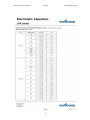
12.1c Capacitor ............................................................................... 74
12.1d Voltage Regulator ................................................................. 76
12.1e DC Generator ........................................................................ 80
12.1f Power bank ............................................................................ 81
12.1g LED Flashlight ..................................................................... 82
2 Catherine Victoria Kennedy UWash Senior Design Project Table of Figures and Tables
Figures
FIGURE 1 – EXPERIMENTAL SETUP OF FARADAY’S LAW……….………..…..…. 8
FIGURE 2 – SCHEMATIC OF AN AXIAL FLUX GENERATOR .…..…………….…... 9
FIGURE 3 - EXAMPLE ENERGY HARVESTER PHOTO AND 3D SCHEMATIC..... 10
FIGURE 4 – ENERGY HARVESTING INTERFACE CIRCUIT…….....…...….........… 11
FIGURE 5 – BLOCK DIAGRAM OF UWASH ENERGY HARVESTING SYSTEM ... 14
FIGURE 6 – DESIGN REQUIRMENTS & UWASH GOAL……….………...............… 18
FIGURE 7 – BATTERY CHARGER SYSTEM ……...…………..……………….......… 24
FIGURE 8 – EXTERIOR OF SALAD SPINNER ………………..……………….......… 26
FIGURE 9 – INTERIOR OF SALAD SPINNER ……………………..…………........… 27
FIGURE 10 – GEAR TRAIN INSIDE SALAD SPINNER ..………..…..………….....… 27
FIGURE 11– BOTTLE DYNAMO ..………………………………..…..………….....… 28
FIGURE 12 – DC GEARMOTOR ..………..…..……..……..……..……………….....… 29
FIGURE 13 – HAND CRANK FLASHLIGHT …..…..……..……..……………….....… 30
FIGURE 14.– SWITCH MODE VOLTAGE REGULATOR ...………..…...…...…...… 31
FIGURE 15 – 5V USB CHARGER AND POWER BANK .………………....….........… 32
FIGURE 16– RECHARGEABLE MICRO LED FLASHLIGHT …………………….…. 33
FIGURE 17 – APPLE IPHONE USB DATA AND CHARGE CABLE ……………...… 33
FIGURE 18 –ENERGY HARVESTER CIRCUIT FLOW CHART ………………….… 37
FIGURE 19 –AC GENERATOR REGUALTING CIRCUIT DIAGRAM …………...… 42
FIGURE 20 –HAND CRANK FLASHLIGHT ………………………………………..… 42
FIGURE 21 –DC GENERATOR REGUALTING CIRCUIT DIAGRAM …………...… 43
FIGURE 22 –METHOD USED TO DRIVE DC GENERATOR ……………………..… 43
FIGURE 23 –INPUT VOLTAGE VS. AVG. PERCENT BATTERY CHARGE……..… 45
FIGURE 24 –INPUT CURRENT VS. AVG. PERCENT BATTERY CHARGE……..… 45
FIGURE 25 –INPUT POWERVS. AVG. PERCENT BATTERY CHARGE…….…..…. 46
FIGURE 26 –LOAD VOLTAGE. AVG. PERCENT BATTERY CHARGE……..…..…. 46
FIGURE 27 –LOAD CURRENT. AVG. PERCENT BATTERY CHARGE……..…..…. 47
FIGURE 28 –LOAD POWER. AVG. PERCENT BATTERY CHARGE…….…………. 47
FIGURE 29 –ELECTRICAL EFFICIENCY. AVG. PERCENT BATTERY CHARGE... 48
FIGURE 30 –AC GENERATOR MULTISIM SIMULATION…….……………………. 52
FIGURE 31 –DC GENERATOR MULTISIM SIMULATION…….……………………. 53
FIGURE 32 –FINAL UWASH SYSTEM DESIGN…….………………..…………...…. 54
FIGURE 33 –PULLEY SYSTEM…….……………………………….....………...….…. 55
FIGURE 34 –ENERGY HARVESTER PULLEY…….…………………………………. 55
FIGURE 35 –GEAR TRAIN IN HAND CRANK FLASHLIGHT…….……..……….…. 56
FIGURE 36 –AC GENERATOR IN HAND CRANK FLASHLIGHT…….………...…. 57
FIGURE 37 –UWASH USER MANUAL……….…….………………..……………..…. 64
3 Catherine Victoria Kennedy UWash Senior Design Project Tables
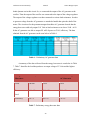
TABLE 1 – ELECTROMAGNETIC ENERGY HARVESTERS …...………………...... 23
TABLE 2 – POWER BANK INDICATOR TRANSLAION…...……………………...... 32
TABLE 3 – LIST OF COMPONENTS FOR THE UWASH …..……………………...... 36
TABLE 4 – PRELIMINARY BOTTLE DYNAMO DATA …….….…….…………...... 38
TABLE 5 – PRELIMINARY DC MOTOR DATA …..……..………………………...... 38
TABLE 6 – PRELIMINARY AC GENERATOR DATA …..……..…………..……...... 39
TABLE 7 – PRELIMINARY ENERGY HARVESTER DATA …..……..……….......... 39
TABLE 8 – WEEKLY BREAKDOWN OF COMPLETION OF UWASH…… ……..... 41
TABLE 9 – TIME TO CHARGE POWERBANK USING AC GENERATOR……........ 49
TABLE 10 – LENGTH OF TIME POWER BANK CAN POWER FLASHLIGHT …... 50 TABLE 11 – HOW MUCH THE POWER BANK CAN CHARGE AN IPHONE TO.... 51 TABLE 12 – FINAL TESTING RESULTS……………………………………………... 59 TABLE 13 – MECHANICAL TO ELECTRICAL CONVERSION EFFICIENCY……. 60 TABLE 14 – PRODUCTION SCHEDULE……………………………………………... 62 TABLE 14 – COST ANALYSIS……………………………………………………….... 63 4 Catherine Victoria Kennedy UWash Senior Design Project 1. Introduction
In many third world countries electricity and water are not easily accessible to the
majority of the population. About 1.5 billion people, about one fifth of the world’s
population, have no access to electricity, and only a billion more only have an unreliable
supply. [1] Washing laundry in a third world country usually consists of walking to the
closest water source, collecting water, and bringing it back home in order to wash and dry
clothes by hand. This is a chore that can consume 6 hours of a persons’ day for 3 to 5 days
a week. Typical washers use around 45 gallons of water or more to wash one full load of
water, which is not possible for a person living in certain areas of third world countries. [2]
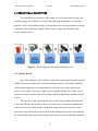
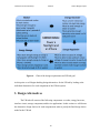
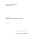
This project, the battery charging hand-powered washing machine, called the
UWash, will be designed for those with the least income living in the poorest nations who
do not have easy access to water or electricity. The UWash is designed to take a physically
laborious task that people in third world countries are already doing and provide a way to
convert their work into usable electricity. The goal of this project is to construct a handpowered washer that can be successfully implemented in an energy harvesting system for
use in a third world country. Specifically, the UWash will charge rechargeable batteries to
be used to provide energy in a bottom-up way, through a low-energy light-emitting diode
flashlight, which may be more sustainable and produce fewer carbon emissions than
centralized schemes, including toxic kerosene lamps. The UWash will convert mechanical
energy provided by a salad spinner into electrical energy with the use of a DC motor
generator. The output voltage of the generator will be regulated in order to charge a
commercial USB based power bank equipped with lithium ion batteries. The output of the
charger can then be used to charge an iPhone or portable LED flashlight through a USB
cable.
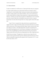
This paper focuses on first defining the background of this project explicitly, and
then detailing the design requirements, alternatives, and final the preliminary proposed
design of the energy harvesting system. We break down the background into discussing the
context and history of energy harvesting systems including the discussion of past work
completed related to energy harvesting. This section also focuses on describing the most
5 Catherine Victoria Kennedy UWash Senior Design Project important issues for this topic in terms of the goals of the project as well as the effects on
society. The next section of the paper focuses on the design requirements, which includes
the specifications and requirements for the project. After, we look into design alternatives,
in which we discuss the justifications for our overall approach and chosen parts. Lastly we
finish by discussing the preliminary proposed design project, the UWash.
2.1 BACKGROUND
Admirably, many projects designed to harvest energy in third world countries are
already being distributed to various people in need of these products. Though the
development of a new energy harvesting system may be challenging, a permeating desire
and responsibility still remains to design one. In order to see where our project fits into the
picture, we must first understand the basic need for the UWash as well as the basic
components of energy harvesting systems.
In the past there have been previous efforts to bring electricity to third world
countries as well as to create devices to make washing laundry a simpler and less
exhausting task. My project seeks to combine these two efforts into one: making a washing
machine that can provide a person with electricity.
1.1a Past Efforts to Make Laundry Washing Easier
In many third world countries laundry is washed by hauling water from far places
in order to wash the clothes by hand. The washer was required to walk miles in order to
collect the water and take it home by the bucket load before washing their clothes one at a
time. Currently, a project designed by Alec Cabunoc and Ji A You, of the Art Center
College of Design in Los Angeles, called the pedal-powered GiraDora washer was
designed for people in third world countries. Their project consisted of a pedal-powered
washer that is a plastic tub tall enough to sit on and requires no electricity to work. The
model was based on sink plungers and salad spinners. The design works by a person sitting
on the tub and repeatedly pressing down on the pedal with their foot. The machine agitates,
cleans and rinses out the clothes. After the clothes are clean a stopcock in the base is
6 Catherine Victoria Kennedy UWash Senior Design Project opened and the pedal works again. At this point the washer becomes a spin drier and the
clothes can be hung to complete drying in a reasonable time. The washer cost only $40
dollars, which is within a reasonable budget to mass-produce [3].
Another design by German-based DesignAffairs Studio called Swirl, is an ecofriendly electricity-free innovative concept for easy laundering on the go. [4] The swirl is a
colorful ball that lets people fill it up with dirty clothes, water and soap and then the
rotational motion of playing soccer does all of the work. The positive aspect of this project
is that it combines work with fun which could make doing laundry an enjoyable chore to a
person living in a third world country [4]. Before we talk about previous work done in the
energy harvesting research field, it is useful to know the basics behind how these types of
systems work.
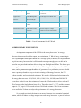
1.1b Energy Harvesting
Mechanical energy harvesting systems that convert mechanical energy into usable
electrical energy represent promising emerging technology to achieve autonomous, selfrenewable, and maintenance-free operation of wireless electronic devices and systems.
Energy harvesting systems consist of three main components: the energy harvester that
converts mechanical energy into electrical energy, an energy harvesting interface circuit
that conditions and regulates the energy, and an energy storage element that stores the
intermittent harvested energy.
1.1c Faraday’s Law
Many energy-harvesting systems use Faraday’s law of electromagnetic induction in
order to power electrical motors, generators, electrical transformers, and inductors.
Faraday’s first law states that any change in the magnetic field of a coil of wire will cause
an electromotive force (emf) to be induced in the coil. The emf induced is called the
induced emf and if the conductor circuit is closed, the current will circulate through the
circuit. This current is called the induced current. Figure 1 shows the experimental setup of
Faraday’s law. There are various ways to change the magnetic field. The first way is to
move a magnet towards or away from the coil. The second method is to move the coil into
7 Catherine Victoria Kennedy UWash Senior Design Project or out of the magnetic field. The third way is to change the area of the coil place in the
magnetic field. The last method is to rotate the coil relative to the magnet.
Figure 1 – Experimental setup of Faraday’s law
Faradays’ second law states that the magnitude of the emf induced in the coil is
equal to the rate of change of flux that linkages with the coil. The product of the number of
turns in the coil and the flux associated with the coil is equal to the flux linkage of the coil.
Faraday’s law is the main component of the energy harvester that the UWash will
implement. [5]
1.1d Bio-engineering Energy Harvesting
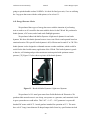
Romero’s article, “Body Motion for Powering Biomedical Devices”, looked into energy harvesting in order to power portable electronic devices. Their design consisted of an axial flux generator powered by human motion. The generator consisted of a gear-‐shaped planar coil and a multipole NdFeB permanent magnet rings along with an attached eccentric weight. The device is able to generate energy through electromagnetic induction on the planar coil when it undergoes a changing magnetic flux as a result of the generator oscillations produced via body motions. Their 1.5 cm3 prototype was able to generate 3.9 µW of power while walking with the generator placed laterally on a person’s ankle. 8 Catherine Victoria Kennedy UWash Senior Design Project This article looked into an available power, which is an important question that would be raised about my project. How much power is available through hand washing your own laundry? The article noted that power generation from energy harvesters is proportional to the proof mass (m), the acceleration (a) squared, and the quality factor (Q), and inversely proportional to the driving frequency (ω) for a system where the driving frequency matches its resonant frequency: P = (1/2)*m* (a2/ ω)*Q. The researchers estimated that the human motion could produce 1mW/cm3 of power from walking, which was enough power to energize low-‐power applications by charging batteries. The generator created by the researchers uses the motion conversion mechanism for body movements found in automatic self-‐winding wristwatches, which consists of rotations or oscillations due to the unbalanced proof mass. The generator also incorporates the approach of axial flux generators used in small-‐scale wind turbines, which consists of multiple pole-‐pair arrangements of permanent magnet (PM) coil. The rotor of the generator is composed of two rings with multiple pole-‐pairs of NdFeB permanent magnets and an eccentric mass. The stator is composed of several stacked layers of a gear-‐shaped planar coil fabricated using thin-‐
film technology. Use of the gear-‐shaped planar coil allows for simplification of the wiring of the two electrical connections per layer. The diagram of the prototype is seen below in Figure 2. Figure 2 – Schematic of the axial flux generator 9 Catherine Victoria Kennedy UWash Senior Design Project Body movement creates the driving force needed to move the rotor eccentric mass. After the mass has been interacted with, it oscillates like a pendulum. The variations of magnetic field due to the rotor oscillations induce a voltage on the planar coil. The AC voltage is then rectified into a DC signal and is stored in a capacitor or a rechargeable battery. [7]
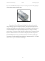
Rao and fellow researchers looked at a fully functional, self-‐sufficient body-‐
worn energy harvesting system for passively capturing energy from human motion, with the long-‐term goal of supplying power to portable electronic devices. The system converted the induced AC voltage to a DC voltage and then boosted and regulated the DC voltage in order to charge a lithium ion battery. The harvester structure was made in two symmetric hemispheres using a Nylon plastic material that was 3D printed. The two halves formed a spherical cavity with a permanent magnet ball on the inside. Both halves were then wrapped with 1400 turns of a 34 AWG copper wire. Figure 3 shows this set up of the energy harvester. Figure 3 – Photograph (left) and 3-‐D schematic (right) of the energy harvester As the person walks the motion of the magnet ball induces a time-‐varying magnetic flux in the coils, which generated a voltage. Connecting an electrical load allows current to flow through the coil, converting mechanical energy into electrical energy. The researchers conditioned the pseudo-‐random output voltage of the harvester by an input-‐powered energy harvesting circuit, which is powered by a time-‐varying voltage. Figure 4 shows a diagram of the circuit. 10 Catherine Victoria Kennedy UWash Senior Design Project Figure 4 – Energy harvesting interface circuit Researchers found that their system successfully scavenged and converted mechanical energy from ordinary human motion into electrical energy for charging a battery. [8] 1.1e Energy Harvesting Efforts in Third World Countries
A design project implemented in a third world country that incorporates electromagnetic energy harvesting is the Soccket soccer ball. The Soccket was designed by two Harvard graduates, Jessica Mathews and Julia Silverman. The Soccket is a soccer ball that has a small generator inside and stores energy by harvesting the kinetic energy. The Soccket was designed to replace kerosene lights in developing third world countries by converting an everyday pleasure into electricity. The small generator inside the Soccket can be used to turn on a small LED lamp for 3 hours after 30 minutes of play. The Soccket has a 6-‐watt output and is just two ounces heavier than a standard soccer ball. As a person plays with the Soccket, a pendulum harnesses the kinetic energy that comes from the movement by turning a generator connected 11 Catherine Victoria Kennedy UWash Senior Design Project to a rechargeable battery. Uncharted Play, the company started by the Harvard undergraduates, has had three versions of the soccer ball. The first design could be inflated and deflated but the major problem was that it did not last very long. The second design was too heavy compared to standard soccer ball. The third design wasn’t that heavy and had a fist-‐sized gyroscope inside. The cost of a standard Soccket and lamp is $99. [6] My project design idea is a combination of the hand powered washer and the Sockket. Combining the kinetic energy generated by hand washing laundry and the energy harvesting aspect of the Sockket resulted in a unique design that would allow for people in third world countries to have access to electricity. 1.1f Ethics
The UWash will be a part of an ecological friendly household system. Washing
laundry in a third world country usually consists of walking to the closest water source,
collecting water, and bringing it back home in order to wash and dry clothes by hand. The
UWash has the potential to make the lives of people in these countries much easier and
provide a way to save water and electricity for others as well. This project would be a green
energy conversion system, which would be beneficial to both the user and to the
environment. Because the UWash converts mechanical energy into electrical it is not
relying on an external electrical power source which is desirable for people living in third
world countries.
This project would also have a social impact. Ideally the UWash would be for a
family, so one per given household. Because there are a limited number of water sources in
low-income third world countries, washing laundry becomes a social chore. Many people
gather around the water source to wash their laundry. The UWash would play a role in this
weekly task, further contributing to communication between family members.
An important safety concern in the design of UWash is the water coming into
contact with the electrical components of the UWash. To keep the user safe, the electrical
components will be isolated from the water that will go into the UWash in order to ensure
the user is not in any danger of electrocuting themselves.
12 Catherine Victoria Kennedy UWash Senior Design Project There are certain ethical related questions we have considered for the UWash. One
of these questions is if the UWash was a success, how would we take it from production to
an actual third world country village. The UWash would need funding in order to be mass
produced and shipped to different countries as well as media support to raise enough
money to do this. The UWash would also need to be cost effective enough in order for
funding to be able to support the cost of multiple UWash machines. We have also
considered the fact that UWash components could break after use, which would lead to the
need for repair. The materials needed to repair the UWash would need to be accessible to
the people owning a UWash. There are also some environmental concerns associated with
the lithium ion batteries we are using as our storage element. There are limitations on
lithium ion batteries when it comes to temperature, which could cause the batteries to fail
or even leak if exposed to much heat. If these batteries needed to be replaced, where would
the people properly dispose of them as to not cause any environmental problems? We have
also considered how difficult it may become to turn the handle of the UWash if it is filled
with an excessive amount of clothes or water. We would not want a person to become
physically injured after using the UWash. If the UWash were to be mass produced and sent
to people in need of it in third world countries it would be beneficial to have some sort of
isolated testing group in order to detect any possible malfunctions we have not already
considered. These are a few of the endless number of questions that are associated with
UWash ethics.
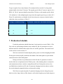
2. Design Requirements
In this section, we describe the specifications and requirements for our hand
powered battery charging washing machine. This will give a clearer understanding as to
what requirements the individual components of the system must satisfy. This section will
also help us in order to classify what, in our perspective, a successful project entails, which
will allow us to easily identify when the final objective has been reached.
13 Catherine Victoria Kennedy UWash Senior Design Project 2.1 BEHAVIORAL OBJECTIVES
The main behavioral objective of the system is to convert mechanical energy into
electrical energy. The UWash must consist of the following components: a washer that
provides a source of mechanical energy, an energy harvester, an energy regulator, a storage
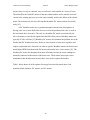
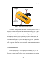
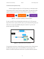
component, and an application. Figure 5 below shows a simple block diagram of the
desired UWash system.
Figure 5 – Block diagram of the desired UWash system 2.1a Washing Machine
One of the main goals of the UWash is to be able to wash at least 5 pounds of soiled
clothing. Therefore a washer device will be needed that is able to wash clothes. Members
of third world countries need a washer that they will be able carry to the nearest water
source, so the washer will need to weigh less than 5 pounds unfilled. The washer can’t be
too heavy because it would be ideal for a younger family member to also be able to lift the
washer.
The basic idea is that a person that needs to wash a load of laundry should be able
to carry the UWash to the location of the nearest water source to wash their laundry there,
or they can leave the UWash at home and bring the water from the nearest water source
back home to the UWash. Next, after both the soiled clothing and water has been placed in
the UWash along with some form of detergent, the person can use the UWash to clean their
14 Catherine Victoria Kennedy UWash Senior Design Project clothes. The dirty water in the UWash should also be able to be drained out of a spout in
the bottom if the water gets too dark. Afterwards, the UWash should be able to be refilled
with clean water in order to continue washing the laundry.
The washer must also use rotational motion in order to wash the clothes so that an
energy harvester can harvest the mechanical rotational motion. We also want to choose a
washer that could eventually be remade from cheaper materials in order to reduce the cost
of the overall system to make it more affordable for members of third world countries.
2.1b Energy Harvester Generator
The second component of the UWash is the energy harvester generator. The energy
harvester aspect of the UWash needs to be able to convert mechanical motion into
electrical energy. The energy harvester should be small enough to be able to attach to the
washer. The energy harvester must also be able to generate enough electricity in order to be
stored in a 5V USB charger/power bank. It is desired for the energy harvester to be able to
produce at least 0.5 Wh of energy after a one-hour use so that after 1 hour a small LED
flashlight could be fully charged and after a 6 hour use an iPhone can be 50% charged.
2.1c Energy Regulation
The third component of the energy harvesting system is energy regulation. Since we
would like to store energy in a 5V USB power bank, the voltage output of the generator
must be regulated. The energy regulator must be able to output DC voltage. Therefore if the
energy harvester outputs AC voltage the regulator should be able to convert it into DC
voltage. The voltage regulator must be able to step up or step down a voltage to 5 Volts for
the 5V USB power bank. The voltage regulator must also be able to easily connect to the
energy harvester. This component should also be small enough to fit easily onto the UWash
washer component.
15 Catherine Victoria Kennedy UWash Senior Design Project 2.1d Energy Storage
The fourth component of the energy harvesting system is the energy storage
component. The UWash should be able to store enough energy to charge a small
rechargeable USB LED flashlight (0.3Wh) and an iPhone battery (5.45 Wh). Therefore our
power bank needs to be able to both be charged by 5V and charge 5V devices. The energy
storage component should also be small enough to fit on the washer.
2.1e Application
The fifth component of the UWash is the application. Since a USB rechargeable
micro flashlight and Apple iPhone USB Data and Charge Cable are the two devices we
want to power with the UWash. The UWash must be able to charge a flashlight so people
in third world countries can have access to light when the sun goes down. These batteries
are typically rated at 0.3 Wh, so the UWash must at least generate this many watt-hours of
energy. The UWash must also be able to charge an iPhone because products similar to the
UWash, like the Sockket, are able to charge up these devices most commonly found in first
world countries. Therefore in order to charge these two devices we need exactly 5 V. A
typical iPhone battery can hold a charge of 5.45 watt-hours, so the UWash should also be
able generate 5.45 watt hours of energy.
2.2 PERFORMANCE OBJECTIVES
Ideally, we would like to have the electromagnetic energy harvester in the UWash
have a maximum power transfer to the electrical load close to 100%. The output of small
electromagnetic energy harvesters requires regulating in order to generate an output voltage
that falls within the allowable operating range of the load electronics. Even after
rectification and boosting, an electromagnetic energy harvester still only has a maximum
power transfer to the electrical load of about 50% of the power flowing into the device. In
order to achieve the maximum potential power of an energy harvester, the power
16 Catherine Victoria Kennedy UWash Senior Design Project conditioning system of the UWash must provide the optimum load for the generator for the
specific input and output conditions. [15]
The UWash must also be easy enough for an average person to rotate the handle.
Assuming the average person using the UWash spins the handle of the salad spinner 30
rotations per minute, and the iPhone draws about 5 Watts of power (charger rated 5V at
1A), using the equation Power = torque X rotational speed = current X voltage, we can see
the torque needed to charge the iPhone is about 1.2 foot pounds, which seems achievable
for an average person to generate.
We can model the voltage regulator, power bank, and application devices as a
variable resistor. If the devices are completely discharged this modeled variable resistor
will draw the most current from the generator meaning a person will have to spin the
handle with more force or faster to achieve the same power output. If the application
devices are 50% charged then they will draw less current and it will be easier to rotate the
generator and handle of the UWash. With this in mind, the UWash handle should never be
“too hard” to spin. So all of the chosen components of the UWash should ensure a user is
able to easily wash their clothes without too much resistance.
The UWash is a success if it can fully charge a rechargeable USB flashlight after a
1-hour use (about 1 wash) and if it can charge an iPhone to at least 50% over a 6-hour use
(about 6 washes). It is assumed the user would be washing and spinning the handle of the
UWash at about 30 RPM, which we will consider an average speed. We also assume one
wash will take about 1 hour of a persons time. This measure of success is discussed in more
detail in section 4.2 “System Analysis”. A chart of the overall goal of the UWash and the
design requirements of each component can be seen below in Figure 6.
17 Catherine Victoria Kennedy UWash Senior Design Project Figure 6 – Chart of the design requirements and UWash goal
At this point we will begin detailing design alternatives for the UWash by looking at the
individual alternatives for each component of the UWash system.
3. Design Alternatives
The UWash will consist of the following components: a washer, energy harvester,
interface circuit, storage component, and device applications. In this section we will discuss
the alternative design choices for each component in order to justify the final design choice
made for the UWash.
18 Catherine Victoria Kennedy UWash Senior Design Project 3.1 COMPONENT ALTERNATIVES
3.1a Washer Alternatives
There were a few choices for the washer component of the UWash. There are a
couple of commercially available washing components, including the Wonderwash, which
is a hand-powered portable washer that can clean clothes in 1 to 2 minutes. The cost of the
Wonderwash is $42.95 The Wonderwash weighs about 6 pounds and is compact in size
making it ideal for anyone who frequently washed small loads of laundry. [16] The
Wonderwash does not operate using a gear system.
Another design alternative for the washer component was a foot powered washing
machine called the GiraDora Washer. This washer requires no electricity and costs about
$40. The washer was created in mind for people in developing countries that lack
electricity and the funds to buy expensive machines. The product developed is a
combination washer and spin-dryer powered by a spring loaded foot pedal. While the
design of this washer is practical, it does not utilize a rotational motion to wash clothes. [3]
3.1b Energy Harvester Alternatives
There are important pros and cons to weigh in choosing an energy harvester for the
UWash. Solar energy has several advantages and disadvantages. Solar energy is renewable,
abundant, sustainable, environmentally friendly, widely available, and reduces electricity
costs. However solar energy harvesting can also be expensive, intermittent since access to
sunlight is limited at certain times during the day, energy storage is expensive, certain solar
cells require materials that are expensive and rare in nature, and it requires space to derive
power. [17]
3.1b-1 Bike Dynamos
Bike dynamos are electromagnetic energy harvesters because they convert
mechanical energy into electrical energy. There are two main types: hub and bottle. Both of
these bike generators are used to power bicycle lights. Unlike actual dynamos that output
19 Catherine Victoria Kennedy UWash Senior Design Project DC power, hub and bottle dynamos output AC power. Bottle dynamos are easy to add to an
existing bike wheel and are generally cost effective. However, bottle dynamos are prone to
slipping in wet conditions because the roller on the bottle dynamo can slip against the
surface of a tire, which will reduce the total amount of electricity generated. [18] Bike
dynamos also typically create more drag than hub dynamos, add wear to the side of the tire
and make a lot of noise when in operation. Hub dynamos are built into the hub of a bicycle
wheel, requiring more installation than bottle dynamos. Hub dynamos are generally about
70% efficient, compared to bottle dynamos with about a 40% efficiency rating. [19] Both
bottle and hub dynamos operate at 6 Volts at 3 Watts.
3.1b-2 AC Motors
Electric motors can be categorized into two types: alternating current (AC) electric
motors and direct current (DC) electric motors. The term motor refers to the energy flow,
electrical to mechanical. Motors can act as generators if used in reverse, meaning the
energy flows from mechanical to electrical. DC motors usually characterize a continual and
standard current flow. AC motors tend to work well for hard systems that need a lot of up
front power. DC motors do not perform that well at producing power over extended periods
of time.
AC electric motors are categorized into two types: synchronous AC motors and
induction AC motors. The synchronous AC motor starts rotating when a sub-multiple of
the supply frequency hits. The rotor magnetic field is the result of the slip ring current or
the result of a permanent magnet. Synchronous motors are divided into two major types
depending on how the rotor is magnetized: non-excited and direct current excited. Nonexcited motors fall into three types: reluctance motors, hysteresis motors, and permanent
magnet motors. [28] The permanent magnet synchronous generator (PMG) is one where
the excitation field is provided by a permanent magnet instead of a coil. Synchronous
corresponds to the fact that the rotor and magnetic field rotates at the same speed. PMG are
commonly used in wind turbine generators. They have several advantages such as being
small in size, low in cost, and have a quick response to varying speed. PMG generators are
also very efficient and simple in structure. The advantage of using permanent magnets are
20 Catherine Victoria Kennedy UWash Senior Design Project the following: they do not require an additional DC supply for the excitation circuit, PMG
avoid the use of slip rings making them simpler and maintenance free, and condensers are
not required for maintaining the power factor in synchronous generators as is required in
induction generators. [26] PWM generators are commonly used in hand crank flashlights
because they are capable of producing more current to charge the built in battery pack the
flashlights come with as well as powering the built in LED’s well. [27] These types of
generators are highly efficient (up to 97%) and reliable because there is no need for
external excitation and conductor losses are removed from the rotor. [29]
Induction motors work on the principle of induction where an electro-magnetic field
(emf) is induced in to the rotor conductors when the rotating magnetic field of the stator
cuts the stationary rotor conductors. There are two types of induction motors based on the
construction: squirrel cage induction motor and slip ring induction motors. Because
induction motors are simple and rugged in construction they are robust and can operate in
any environmental condition. These motors are also cheaper in cost and maintenance free
due to the absence of brushes, commutators, and slip rings. The induction asynchronous
AC motor turns a little slower than the standard supply frequency. The magnetic field on
the rotor works with the help of the induced current. AC induction motors have long life
expectancies compared to DC motors, making them desirable for use as generators. [12].
Induction motors vary in efficiency from 85% to 97%. [30]
3.1b-3 DC Motors
DC motors are categorized into brush motors and brushless motors. A brushed DC
motor is composed of a rotating set of wound wire coils, called an armature, which acts as
an electromagnet with two poles. A mechanical rotary switch called a commutator reverses
the direction of the electric current that flows through the armature so that the poles of the
electromagnet push and pull against the permanent magnets on the outside of the motor. As
the poles of the armature pass the poles of the permanent magnets, the commutator reverses
the polarity of the armature electromagnet. During the instant of switching polarity inertia
keeps the motor rotating in the correct direction [9]. Brushed DC motors are about 75%80% efficient. [10] The DC brush electric motor is the most common type of motor used
21 Catherine Victoria Kennedy UWash Senior Design Project because they are easy to construct, very cost effective, and available in a variety of sizes.
The tradeoff for the brush DC motors is that the carbon brushes used to transfer electrical
current to the rotating part wear over time and eventually result in the failure of the electric
motor. These motors are also less efficient than brushless DC motors and are electrically
noisy [10].
A DC brushless motor uses a permanent magnet external rotor, three phases of
driving coils, one or more Hall effect devices to sense the position of the rotor, as well as
the associated drive electronics. The coils in a brushless DC motor are activated by the
drive electronics as cued by the signals from the Hall effect sensors. Brushless motors are
typically 85-90% efficient. [23] Brushless DC motors also eliminate the problem due to the
brushes that DC brush motors have. However, these motors are also more expensive and
require complicated drive electronics in order to operate. Brushless motors can be driven to
much higher RPM limits than brush DC motors and usually have a lower inertia [11]. The
brushless DC motor also dissipates heat more efficiently because the stator windings are
thermally connected to the outside of the motor case. These motors also require lower
maintenance than brush motors because there is no need to replace the brushes.
Table 1 below shows all of the options for energy harvesters discussed above: hub
dynamos, bottle dynamos, DC motors, and AC motors.
22 Catherine Victoria Kennedy UWash Senior Design Project Table 1 – Electromagnetic energy harvester comparison
3.1c Interface Circuit Alternatives
In order to understand the type of interface circuit the UWash system needs it is
important to review the basics behind battery charging systems in order to see the interface
circuit’s role in the system. A battery charger system is the system used to draw energy
from a utility grid, store it in a battery, and release it to power a device. Designers of these
circuits try to maximize the energy efficiency of their devices in order to ensure long
operation times between charging. It is not possible to charge a battery by directly plugging
it into a standard wall outlet, therefore a series of power conversion steps needs to be
performed in order to change the high AC voltage from the power outlet into the
appropriate amount of low DC voltage that the battery can use. Battery charging circuits
work by first reducing the voltage form the utility level to the lower voltage at which the
23 Catherine Victoria Kennedy UWash Senior Design Project batteries can operate, second by rectifying the AC electricity into DC electricity, and
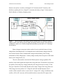
thirdly by regulating the low-voltage DC current into the battery. Figure 7 below shows a
block schematic of a battery charging system.
Figure 7 – Block schematic showing the general configuration of a multi-piece battery
charger system with a discrete power supply and charge control circuitry. The efficiency
calculation is made over a 24-hour charge and maintenance period and a 0.2 C discharge
for the battery.
Battery chargers can operate in three modes. In active mode the battery is being
charged from a discharged state. It is during this state in which battery chargers draw the
most current form the outlet. In maintenance charge mode the battery state is being
maintained at a fully charged state. A battery charger usually draws less power in this mode
than in active charge mode. [13]
The role of the interface circuit in the UWash system is energy regulation. The
interface circuit must regulate the output of the energy harvester. The interface circuit must
be capable of converting any voltage produced by the energy harvester to exactly 5 Volts.
The type of interface circuit needed depends on the output voltage of the energy harvester.
If the energy harvester produces AC voltage like the bottle and hub dynamos, then a
rectifier will be needed in order to convert the AC voltage to DC voltage. In addition to the
rectifier, a DC-to-DC converter will be needed in order to convert the DC output of the
24 Catherine Victoria Kennedy UWash Senior Design Project rectifier to exactly 5 V. If the output of the energy harvester is DC then only a DC-to-DC
converter will be needed. There are a few options for DC to DC converters including a
step up converter, step down converter, or both a step up and step down converter.
3.1d Energy Storage Alternatives
There are various types of rechargeable batteries that can store electrical energy.
Depending on the chemicals involved and the overall design, a battery behaves differently
when being used and charged.
Lithium ion batteries are low maintenance, can provide high current to applications,
are lightweight, and also have improved safety circuitry to prevent overcharge in turn
preventing electrolyte leakage. [14] Alkaline rechargeable batteries have a long shelf life
and are available in household sizes. They lose their charge gradually, giving the user
plenty of warning that it’s time to change or recharge. The downside of these batteries is
that they don’t fully recharge, so that battery capacity shrinks rapidly with each charge
cycle. Nickel cadmium batteries are rechargeable, however they are hazardous when
disposed of. These batteries also have low capacity and will not properly recharge if they
are not completely drained. [20]
3.1e Application Device Alternatives
Since the devices that need to be charged are a portable flashlight and an iPhone we
will look into flashlights an iPhone chargers that can be charged via a 5V USB port. The
Apple iPhone USB Data and Charge Cable is capable of plugging into an iPhone and
charging it through a standard USB port. Since 5 Volt USB cables to charge iPhones are
pretty standard there aren’t many alternatives besides choosing cables to charge specific
types of iPhones like the 5s or the iPhone 6. There are many brands of rechargeable USB
flashlights that can satisfy the application design requirement. One such option is a
rechargeable micro flashlight made by Minitorch that consists of a white LED rated from
8000 to 12000 microcandella. This USB flashlight is able to fully charge in 2 hours and is
capable of providing 2+ hours of light after a full charge. The battery used in this device is
25 Catherine Victoria Kennedy UWash Senior Design Project a lithium ion battery rated at 300mAh at 1V or (0.3Wh). Another option is a mini USB
rechargeable 20-Lumen LED flashlight by FASTTECH. This flashlight claims to have 150
minutes of working time after charging for 15-20 minutes. [22]
4. Preliminary Proposed Design
4.1 CHOSEN COMPONENTS
The project we have developed, the UWash, is a battery charging hand powered
washing machine. The components of the energy harvesting system we have chosen
specifically satisfy the design requirements listed in section 2.
4.1a Washer Choice
The mechanical energy source of the UWash will come from the rotational motion
of a salad spinner. We chose to use a five-gallon salad spinner purchased from KaTom
because it is light enough to carry, capable of washing a small load of laundry, has a built
in drainage system, operates based on rotational motion, and has a built in gear system.
The salad spinner lid size and ultimate capacity influenced the rest of the components we
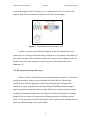
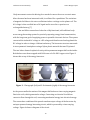
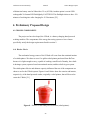
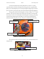
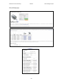
chose to use for the UWash system. Figures 8 and 9 below show the exterior and interior,
respectively, of the hand powered washer, originally a salad spinner, that will be used to
create the UWash. [21]
Figure 8 – Exterior of the hand-powered washer (salad spinner).
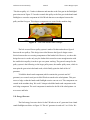
26 Catherine Victoria Kennedy UWash Senior Design Project Figure 9 – Interior of the hand-powered washer (salad spinner).
The salad spinner we ordered has a built in gear train that we will utilize to generate
electricity with our motor energy harvester. A picture of the gear train is seen below in
Figure 10.
Figure 10 – Salad Spinner with built in gear train.
The top 2 gears have a 2.5:1 gear ratio. We plan on 3D printing a gear to fit the energy
harvester we purchased to increase the ratio even more to obtain the maximum amount of
RPM’s. We will design our gear ratio based on the assumption that the average UWasher is
27 Catherine Victoria Kennedy UWash Senior Design Project going to spin the handle at about 30 RPM’s. It is ideal for final gear ratio, if we are utilizing
the 2 top gears that come with the salad spinner, to be at least 3:1.
4.1b Energy Harvester Choice
We purchased three types of energy harvesters with the intention of performing
tests on each to see if it would be the most suitable choice for the UWash. We purchased a
bottle dynamo, a DC motor, and a hand crank flashlight generator.
We purchased a Busch & Muller Dymotec 6 light travel dynamo for our bottle
dynamo. We chose this bottle dynamo because it was cost effective and operated based on
rotational motion. This specific bottle dynamo is 40% efficient and is rated 6V at 3W. This
bottle dynamo is also designed to withstand extreme weather conditions, which would be
useful for the third world country application of the UWash. This bottle dynamo is gentle
to the tire, self-cleaning and provides maximum traction paired with optimum contact
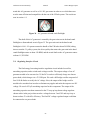
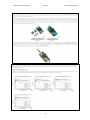
pressure. [32] Figure 11 below shows a picture of the bottle dynamo.
Figure 11 – Busch & Muller Dymotec 6 light travel dynamo
We purchased a 19:1 metal gear motor from Pololu Robotics & Electronics. We
purchased this motor because it was cheap, can operate as a generator, and contained a built
in gear system that we could utilize. This 2.05" × 1.45" × 1.45"gearmotor is a powerful
brushed DC motor with 18.75:1 metal gearbox intended for operation at 12 V. The units
have a 0.61"-long, 6 mm-diameter D-shaped output shaft. Some key specifications include
28 Catherine Victoria Kennedy UWash Senior Design Project that at 12 V: 500 RPM and 300 mA free-run, 84 oz-in (5 kg-cm) and 5 A stall. [33] Figure
12 below shows a picture of the DC motor.
Figure 12 – 19:1 DC Metal Gear Motor
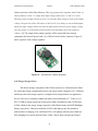
We purchased a Dorcy LED Dynamo Flashlight. The self-powered, renewable
energy technology requires no recharging of batteries. The fold out hand crank winds up
and charges the flashlight conveniently and quickly. The flashlight also dual functions as a
3-bulb LED flashlight and a 5-bulb LED blinking flashlight. One minute of cranking
results in about 3 to 6 minutes of light if the light is completely dead. The battery inside the
dynamo is a lithium ion 2032 3.6V coin cell that is charged by the crank. The generator
inside the flashlight is driven by a gear train discussed more in section 4.4 of this report.
The generator is a small permanent magnet brushless AC generator rated 8-9V. [34] Figure
13 below shows a picture of the hand crank flashlight.
29 Catherine Victoria Kennedy UWash Senior Design Project Figure 13 – Hand Crank Flashlight Generator
We ultimately ended up choosing both the DC motor and the permanent magnet AC
generator for the energy harvester for the UWash. After creating gears for both, in order to
mechanically connect the energy harvesters to the salad spinner, we will decide which one
produces the most watt-hours in one hour and is the most efficient. We chose to decide
between these two generators because they are both cost effective, highly efficient, and
proved to be able to generate 0.5 Watts of power after an hour or mechanical rotation,
which is the ultimate measure of success for the UWash energy harvester. We chose these
two generators after analyzing the data from a bottle dynamo, DC motor, and permanent
magnet AC generator. These results are seen in section 4.4 of this report titled “Preliminary
Experiments”.
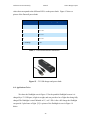
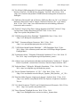
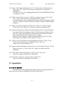
4.1c Energy Regulator Choice
In order to deliver exactly 5 Volts to the storage component we chose a 5V step
up/step down switch mode voltage regulator. We choose to use a switch mode voltage
regulator for our energy regulator because it is 80% efficient compared to linear regulators
30 Catherine Victoria Kennedy UWash Senior Design Project which can be have half of the efficiency. The step-up/step-down regulator from Pololu we
chose produces a fixed 5 V output from input voltages between 2.9 V and 30 V while
allowing a typical output current of up to 2 A when the input voltage is close to the output
voltage. The part also offers efficiencies of 80% to 90%. Its ability to convert both higher
and lower input voltages makes it useful for applications where the power supply voltage
can vary greatly, as with batteries that start above but discharge below the regulated
voltage. [24] The output of the voltage regulator will be connected to the storage
component, the Duracell power bank, via a USB A Female Solder Connector. Figure 14
shows a picture of the voltage regulator.
Figure 14 – Switch mode Voltage Regulator
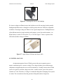
4.1d Energy Storage Choice
The chosen storage component of the UWash system was a Duracell power bank.
We chose this storage component because it can charge and be charged by a 5V USB port
and because the total storage capacity is enough to fully charge both of our application
devices. This device contains a lithium ion battery rated 2600mAh at 3.7 Volts, or 9.62
Wh. 9.62Wh of storage means our chosen power bank can hold more than 5.45Wh and
0.3Wh, which are the energy storage capacities of the iPhone battery and LED flashlight
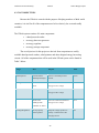
battery respectively. This power bank has 4 LED’s that light up one after another to
indicate that it is charging. The 4 different LED’s will light up after the power bank has
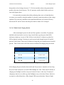
been charging for a certain amount of time. Table 2 below shows the percent charged
31 Catherine Victoria Kennedy UWash Senior Design Project values that correspond to the different LED’s on the power bank. Figure 15 shows a
picture of the Duracell power bank.
LED
Percent of Battery Charged (%)
4
80 – 100
3
60 – 80
2
40 - 60
1
20 - 40
1 (flashing)
< 20
0
0
Table 2 – Power bank indicator translation
Figure 15 – 5V USB charger and power bank
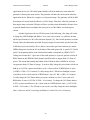
4.1e Application Choice
We chose the flashlight seen in Figure 13 for the portable flashlight because it is
charged by a 5V USB port, is light in weight, and can provide a lot of light after being fully
charged The flashlight is rated 300mAh at 1V, or 0.3 Wh. After a full charge the flashlight
can provide 2 plus hours of light. [25] A picture of the flashlight is seen in Figure 16
below.
32 Catherine Victoria Kennedy UWash Senior Design Project Figure 16 – Rechargeable micro LED flashlight
We chose to charge an iPhone because the Sockket soccer ball can charge both a portable
flashlight and iPhone and we thought it would be good to have the UWash be comparable
in abilities. Choosing to charge an iPhone is also a good comparison to a flashlight because
of the different needs of people in third world countries versus first world countries. An
iPhone battery is rated at 1140 mAh at 5V, or 5.45 Wh. Figure 17 shows a picture of the
USB cable needed to charge an iPhone.
Figure 17– Apple iPhone USB data and charge cable
4.2 SYSTEM ANALYSIS
An important equation for our UWash system is the power equation: power =
torque x rotational speed = current x voltage. The voltage regulator, power bank storage
component, and application devices can all be modeled as a variable resistor in the UWash
system. In a perfect world the voltage across this “variable resistor” part of the system is
constant at 5 Volts. Therefore, if voltage is constant the thing that is changing in our system
is current. The current drawn from the generator all depends on how charged our
33 Catherine Victoria Kennedy UWash Senior Design Project application devices are. The salad spinner handle will be the hardest to rotate when the
generator is drawing the most current. The generator will draw the most current when the
application device, iPhone for example, is at 0 percent charge. The generator will draw half
that amount of current when the iPhone is at 50% charge. Therefore, when the generator is
drawing the most current the UWasher will have to either rotate the handle with more force
or spin the handle faster to maintain the same power as if the iPhone was drawing less
current.
Another big question for our UWash system is the following: How long will it take
to charge the LED flashlight and iPhone? As a worst-case scenario, we will base our data
off the specifications of a 40% efficient bottle dynamo [31]. Since bottle dynamos are made
for bike riders the information provided for power output is based on the speed of the biker
in kilometers per hour (km/hr). We are able to convert the speed into rotations per minute
(RPM) taking into account the 8.5-inch radius of the salad spinner lid. A speed of 2.5 km/hr
and 8.5 inch spinning radius of the salad washer handle corresponds to a RPM of 30.72.
Taking into account the 3:1 gear ratio of the salad spinner we expect to generate at least 90
RPM. Based on this RPM the bottle dynamo should be able to output about 0.5 Watts of
power. This means that rotating the handle of the UWash at about 30 RPM for one hour
can generate about 0.5 Watts of energy. In order to fully charge the power bank, which can
hold up to 9.62 Wh, a person would have to do a 1 hour wash at 30 RPM about 19 times
(9.62Wh / 0.5Wh = 19.24 washes). To fully charge the 0.3 Wh micro flashlight a person
would have to do a 1 hour wash at 30 RPM about 1 time (0.3 Wh / 0.5Wh = 0.6 washes).
To fully charge the 5.45 iPhone battery a person would have to do a 1 hour wash at 30
RPM about 11 times (5.45 Wh / 0.5Wh = 10.9 washes). To charge the 5.45 iPhone battery
to 50% a person would have to do a 1 hour wash at 30 RPM about 6 times { (5.45/2) Wh /
0.5Wh = 5.45 washes }. The UWash is a success if it can fully charge the micro flashlight
after a 1-hour use and if it can charge an iPhone to at least 50% over a 6-hour use.
34 Catherine Victoria Kennedy UWash Senior Design Project 4.3 COST OBJECTIVES
Because the UWash is created with the purpose of helping members of third world
countries, it is vital for all of the components used to be relatively low cost and readily
available.
The UWash system consists of 4 main components:
•
a hand powered washer
•
an energy harvester generator
•
an energy regulator
•
an energy storage component.
The cost objectives for this project are derived from comparisons to readily
available hand-powered washers, salad spinners and other designed energy harvesting
circuits. All of the components that will be used in the UWash system can be found in
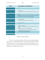
Table 3 below.
Stage
Part
Purpose
Price
Salad Spinner:
5 Gallon Plastic
Serves as the hand powered
$ 100
Salad Spinner/Dryer
washer
19:1 Metal Gear
Converts rotational mechanical
motor
energy into AC voltage.
Bottle Dynamo
Converts rotational mechanical
Energy Harvesters:
$ 25
$ 25
energy into DC voltage.
Hand Crank
Converts rotational mechanical
Flashlight with
energy into AC voltage.
$ 14
brushless AC motor
Voltage Regulation:
5V step up/step
Steps the voltage up/down to
down regulator
exactly 5 Volts for the USB
charging devices
35 $5
Catherine Victoria Kennedy Energy Storage:
UWash Senior Design Project Duracell Power
Charges and is charged through 5
Bank
V USB port.
Application
USB Rechargeable
Provide light to a UWash user
$5
Devices:
Micro Flashlight
Charge an Apple IPhone
-----
USB female solder
Connects output of voltage
$1
connecter
regulator to storage component
Apple IPhone USB
$ 30
Cable
Miscellaneous Parts:
Total Price:
$ 205
Table 3 – List of components for the UWash
4.4 PRELIMINARY EXPERIMENTS
An important component of the UWash is the energy harvester. The energy
harvester chosen must be able to output, at the minimum, 0.5 Wh of energy, assuming the
user is spinning the salad spinner handle at an average speed (30 RPM). It is important that
we pick an energy harvester that is efficient and can output enough power to able to be
stored in our power bank and later able to charge our flashlight and iPhone. The three types
of energy harvesters we considered include the following: a bottle dynamo, a brush DC
motor, and a permanent magnet brushless AC generator. For a preliminary test we decided
to use a prototype board to set up a circuit consisting of the energy harvester, the 5V
voltage regulator, and varying load resistances. We used the following load resistances for
the energy harvester tests: 10 Ω, 50 Ω, 100 Ω, 1 kΩ, 10 kΩ, 100 kΩ, and a 200 kΩ. We
chose these values for our load resistances because the UWash needs to deliver at least 0.5
Wh of energy to the load after one hour of use. Therefore, since P = V2/R, and the regulator
output is 5 V, to get 0.5 W we need at least a 50 Ω load resistance. We look at resistances
above and below 50 ohms to analyze the performance of the energy harvesters.
So, as stated previously the input to the energy harvester is a mechanical rotational
motion, which will induce a voltage output from each energy harvester. As part of each test
36 Catherine Victoria Kennedy UWash Senior Design Project we measured the following: the input voltage to the regulator, the output voltage of the
regulator, the input current to the regulator, and the current through the load resistor. From
these measurements we were able to calculate the input power to the regulator, the output
power across the load and the efficiency of the energy harvester for various loads. Figure
15 below shows a general flow chart of the circuit we used to test each energy
harvester
Figure 18 – Energy harvester circuit flowchart
In order to test the bottle dynamo, which outputs AC voltage, we needed to first
convert the output into DC voltage so that it could be regulated by our 5V step up/step
down voltage regulator. In order to do this we first made a rectifier consisting of four
n4148 diodes and a 470 µF smoothing capacitor. We then connected the output of the
rectifier to the voltage regulator. The output of the regulator was connected to various load
resistors. In order to generate voltage out of the bottle dynamo the cap was hand spun as
fast as possible. The circuit test for the bottle dynamo showed that the energy harvester
could only output 5.12 Volts at load resistances at or above 100 kΩ. At 200 kΩ the bottle
dynamo was able to output about 100 mW of power at 10.7% efficiency. The data obtained
from the bottle dynamo can be seen below in Table 4. The input voltage refers to the
voltage into the regulator. The output voltage refers to the voltage out of the regulator. The
input current is the current going into the regulator. The load current is the current through
the load.
37 Catherine Victoria Kennedy UWash Senior Design Project Table 4 – Preliminary bottle dynamo data
There was no need to use a rectifier for the brush DC motor because the motor
already outputs DC voltage. So for the DC motor test all we had to do was connect the
output of the motor to the voltage regulator, then to various load resistances. In order to
generate voltage from the motor we attached a handle that spins the shaft of the motor. The
DC motor we purchased already has a built in gear system with a ratio of 19:1. The circuit
test for the brushless DC motor showed that the energy harvester could only output 5.1
Volts at load resistances at or above 50 Ω. At 50 Ω the DC motor was able to output 510
mW of power at 89% efficiency. The data obtained from the DC motor can be seen below
in Table 4=5.
Table 5 – Preliminary DC motor data
The permanent magnet AC generator we used was from a hand crank flashlight.
The flashlight has its own gear train that drives the motor. After taking the flashlight a part
I was able to see that there are 3 sets of motors that make the gear train each with a gear
ratio of 40:12, making the total gear ratio about 37:1. Because the permanent magnet
brushless AC generator outputs AC voltage we used the same rectifier we used for the
38 Catherine Victoria Kennedy UWash Senior Design Project bottle dynamo test in this circuit. So, we connected the output of the AC generator to the
rectifier. Then the output of the rectifier was connected to the input of the voltage regulator.
The output of the voltage regulator was then connected to various load resistances. In order
to generate voltage from the AC generator we attached a handle that spins the shaft of the
motor. The circuit test for the permanent magnet brushless AC generator showed that the
energy harvester could only output 5.01 Volts at load resistances at or above 50 Ω. At 50
Ω the AC generator was able to output 501 mW of power at 70.4% efficiency. The data
obtained from the AC generator can be seen below in Table 6.
Table 6 – Preliminary AC generator data
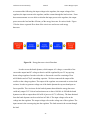
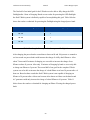
A summary of the data collected from the energy harvesters is seen below in Table
7. Table 7 identifies the load that produces an output voltage of 5 Volts and the highest
efficiency.
Energy
Bottle Dynamo
Brush DC Motor
Harvester:
Permanent Magnet
AC Generator
Load:
100 kΩ
50 Ω
50 Ω
Power across
100 mW
510 mW
501 mW
10.7 %
89.0 %
70.4 %
load:
Efficiency:
Table 7– Preliminary energy harvester data
39 Catherine Victoria Kennedy UWash Senior Design Project Based on the results the brush DC motor and permanent magnet AC generator were the
most efficient and produced similar power ratings across the load resistors. However, it is
important to remember that a different gear ratio was used to drive the two generators. The
gear ratio that drives the AC generator is 37:1 versus the gear ratio that drives the DC
motor, which is 19:1. We expect the power output and efficiency of the DC motor to
increase if we increased the gear ratio to 37:1.
Since both the DC motor and AC generator were more efficient than the bottle
dynamo, the choice of energy harvester must be between these two energy harvesters.
Because the UWash also must incorporate the salad spinner we will have to mechanically
connect the energy harvester to the salad spinner. Both the DC motor and AC generator
will require at least one gear to be made in order to allow the rotational motion of the salad
spinner to be converted into electrical energy by the energy harvester. Because the
mechanical gear will change the data we obtained for the DC motor and AC generator I
believe it will be worth it to make a gear for both the DC motor and the AC generator and
see which generator will perform better.
4.5 SCHEDULE BREAKDOWN
The weekly break down of how the UWash will be completed is seen below in
Table 8. Winter term we will assemble and test the final functioning UWash.
40 Catherine Victoria Kennedy WEEK
UWash Senior Design Project GOAL
1
Test salad spinner washing capabilities
2
Test the chosen motor with storage element.
3
Test the storage element with charging applications.
4
Design way to fit motor, charging circuit, and storage
component on salad spinner
5
Create and order any parts needed to mechanically fit
components on salad spinner
6
Work on altering washer to incorporate motor with gear
7
Connect motor generator storage element and test how
well the system works with the salad spinner
8
Test UWash and make changes as needed to design.
9
Test UWash while actually washing laundry
10
Make changes to ensure user safety
Collect final test data and construct user manual and final
report
Table 8 – Weekly breakdown of the completion of the UWash
5. Final Design and Implementation
5.1 GENERATOR EXPERIMENTS
In order to choose between the AC generator from the hand crank flashlight and the
19:1 DC gear motor we performed a series of tests in order to see which generator was the
most efficient and compatible with the rest of the UWash system.
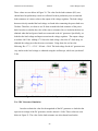
41 Catherine Victoria Kennedy UWash Senior Design Project 5.1a AC Generator Experiment Set Up
To test the AC generator in the hand crank we disassembled the flashlight, took out
the LED’s and the charging circuit inside, and replaced it with our own regulation circuit
seen below in Figure 19. A picture of the hand crank flashlight is also seen below in Figure
20. The crank of the AC generator was able to turn on average about 120 RPM, taking into
account the 94.6:1 gear ratio, the generator spun at about 11,352 RPM.
Figure 19 – AC Generator Regulating Circuit Block Diagram
Figure 20 – Hand crank flashlight
This circuit is composed of five parts. First there is an AC generator, outputting AC
voltage. Next, the full bridge rectifier converts the AC voltage to DC. The smoothing
capacitor gets rid of any ripple voltage present in the output of the bridge rectifier. The
voltage regulator then takes the DC output voltage of the capacitor and steps it up or down
to about 5 Volts to be stored in the final component, the power bank.
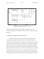
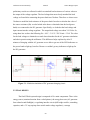
42 Catherine Victoria Kennedy UWash Senior Design Project 5.1b DC Generator Experiment Set Up
In order to regulate the output of our 19:1 DC gear motor we connected the output
of the generator to the 5V step up / step down voltage regulator. The output of the voltage
regulator was then connected to the power bank. This flow is seen below in Figure 21.
Figure 21 – DC generator regulating circuit block diagram
We used a second DC motor and spring shaft in order to drive our 19:1 DC gear motor.
Figure 22 below shows a picture of the DC motor set up. The shaft of the DC generator was
able to turn on average about 180 RPM, taking into account the 19:1 gear ratio, the
generator spun at about 3,420 RPM.
Figure XX – Method used to drive DC generator
Figure 22 – Method used to drive DC generator
It is noteworthy to notice there is a huge difference (greater than a factor of three) between
the RPM the DC generator spins at versus the RPM the AC generator spins at. This
difference will affect the performance results for the AC generator and the DC generator.
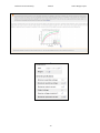
43 Catherine Victoria Kennedy UWash Senior Design Project 5.1c Generator Results
In order to test both the AC and DC motors we looked specifically at the power going into
the voltage regulator and the power going into the load (the power bank). In order to
calculate power we first found the voltage, with respect to ground, in the lead attached to
the input of voltage regulator (Vin) using the multimeter. Next we used a 0.08 Ω power
resistor and the multimeter to find the current going into the voltage regulator input (Iin).
Therefore, to find the power into (Pin) the regulator we multiplied the Vin x Iin. To find the
power into our power bank load we performed the same process as before, except the
measurements were taken from the output lead of our voltage regulator instead of the input
lead.
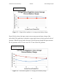
Figure 23 below is a graph of the voltage with reference to ground before the
regulator versus the average percent battery charge of the power bank for the AC generator
and DC generator tests. The average percent batter charge is based on the data sheet for the
power bank seen in Table 2. The table indicated that one lit LED corresponded to the
power bank being charged between 20 and 40 percent, indicating an average charge of 30
percent. The second LED lights up when the power bank is between 40 to 60 percent
charged, the third LED for 60 to 80 percent charged and the last LED will light up between
80 and 100 percent charged. The graph shows us that the average voltage before the
regulator is always greater for the DC generator. When the power bank is between 20 and
30 percent charged the voltage before the regulator for the AC generator is 2.85 V, versus
the DC motor which is 3.05 V.
44 Catherine Victoria Kennedy UWash Senior Design Project Figure 23 – Voltage before regulator vs. average percent battery charge
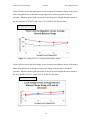
Figure 24 below shows the input current versus average percent battery charge of the
power bank. The graph shows us that the average input current is always greater for the AC
generator. When the power bank is between 20 and 40 percent charged the input current to
the AC generator is 449.375 mA versus 259.375 mA for the DC generator.
Figure 24 – Current into regulator vs. average percent battery charge
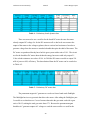
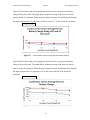
45 Catherine Victoria Kennedy UWash Senior Design Project Figure 25 below shows the input power versus average percent battery charge of the power
bank. The graph shows us that the average input power is always greater for the AC
generator. When the power bank is between 20 and 40 percent charged the input current to
the AC generator is 1278.472 mW versus 791.09 mW for the DC generator.
Figure 25 – Input power vs. average percent battery charge
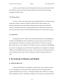
Figure 26 below shows the load voltage versus average percent battery charge of the power
bank. The graph shows us that the average load voltage is always greater for the AC
generator. When the power bank is between 20 and 40 percent charged the input current to
the AC generator is 4.06 V versus 3.895 V for the DC generator.
Figure 26 – Load voltage vs. average percent battery charge
46 Catherine Victoria Kennedy UWash Senior Design Project Figure 27 below shows the current going into the load versus average percent battery
charge of the power bank. The graph shows us that the average load current is always
greater for the AC generator. When the power bank is between 20 and 40 percent charged
the input current to the AC generator is 230 mA versus 151.75 mA for the DC generator.
Figure 27 – Load current versus average percent battery charge
Figure 28 below shows the current going into the load versus average percent battery
charge of the power bank. The graph shows us that the average load current is always
greater for the AC generator. When the power bank is between 20 and 40 percent charged
the input current to the AC generator is 933.8 mW versus 605.483 mW for the DC
generator.
Figure 28 – Load power versus average percent battery charge
47 Catherine Victoria Kennedy UWash Senior Design Project Figure 29 below shows the electrical efficiency versus average percent battery charge of
the power bank. Electrical efficiency is defined as power out (load power) divided by
power into the regulator. The graph shows us that the average electrical efficiency is
relatively similar for the AC and DC generators expect for when the power bank is almost
100% charged. When the power bank is between 20 and 40 percent charged the AC
generator efficiency is 73.04 percent, versus 76.54 percent for the DC generator. When the
power bank is between 80 and 100 percent charged the AC generator efficiency is 80.62
percent, versus 35.08 percent for the DC generator.
Figure 29 – Electrical efficiency versus average percent battery charge
After doing some preliminary charging with the AC generator for about 1 hour we were
able to get one of the LED indicators on the power bank to light up, however after two
hours of charging via the DC generator we were not able to get any indicator LED’s to light
up. Based on all of the results we found we chose to move forward with the AC generator
rather than the DC generator. We chose the AC generator because on average the power
delivered to the load was always greater than the power delivered to the load by the DC
generator. Because we are charging via a 5 V USB port we wanted to choose the generator
48 Catherine Victoria Kennedy UWash Senior Design Project that produces a load voltage closest to 5 V. We also needed to choose the generator that
produces the most electrical power. The AC generator satisfies both of these needs as is
seen in the figures above.
It is noteworthy to mention that while performing these teste we found that there
was some error caused by using the multitier to calculate current into and out of the voltage
regulator. This error may contribute to the significant difference in electrical efficiency
between the DC and AC motor when the power bank is almost 100 % charged.
5.1d AC Hand Crank Charging Results
After measuring the power in and out of the regulator we used the AC generator
attached to the hand crank to see how long it would take to get the power bank LED
indicators to light up. As seen in Table 9 below it took about 15 minutes to get the first
LED to light up, meaning 15 minutes to get the power bank charged between 20 and 40
percent. It takes about 7 hours and 45 minutes to charge the power bank between 80 and 90
percent. Table 9 below shows all of the results we obtained for charging the power bank
Power Bank Percent Charged (%)
AC Motor
20 – 40
15 min.
40 – 60
2 hours 15 min.
60 – 80
4 hours 35 min.
80 – 100
7 hours 45 min.
Table 9 – Time to charge power bank with AC generator using hand crank
After charging the power bank to between 80 and 100 percent we wanted to see how long
the power bank could power our small LED flashlight for. After 7 hours and 45 minutes of
charging our flashlight was able to stay on for about 16 hours. After only 15 minutes of
charging by hand we were able to get the flashlight to stay on for about 2 hours. Earlier in
our report we talked about how a fully charged LED can provide about 2 hours of light.
49 Catherine Victoria Kennedy UWash Senior Design Project The first half of our initial goal for the UWash was to be able to fully charge the LED
flashlight after 1 hour of charging. Based on our results for powering the LED flashlight
the final UWash system is definitely capable of accomplishing this goal. Table 10 below
shows the results we obtained for powering the flashlight using the charged power bank.
Power Bank Percent Charged (%)
Duration of time flashlight stays on for (hours)
20 – 40
2
40 – 60
5
60 – 80
10+
80 – 100
16+
Table 10 – Length of time power bank can power flashlight for
After charging the power bank a second time to between 80 and 100 percent we wanted to
see how much our power bank could increase the charge of a fully dead iPhone to. After
about 7 hours and 45 minutes of charging we were able to increase the charge of our
iPhone to about 41 percent. After only 15 minutes of charging by hand we were only able
to charge our iPhone to 5 percent. The second half of our goal for the complete UWash
system was to be able to increase the charge of a dead iPhone to at least 50 percent after a 6
hour use. Based on these results the final UWash system is not capable of charging an
iPhone to 50 percent after a 6 hour use because after almost an 8 hour use the hand crank
AC generator could only increase the charge of a dead iPhone to 41 percent. Table 11
below shows the results we obtained for charging an iPhone 5S using the charged power
bank.
50 Catherine Victoria Kennedy UWash Power Bank Percent Charged (%)
Senior Design Project Percent increase in iPhone Charge (%)
20 – 40
5
40 – 60
11
60 – 80
26
80 – 100
41
Table 11 – Percent charge power bank can increase a 0 percent initially charged
iPhone to
5.1e Simulated AC and DC Circuits
We used Multisim to simulate the AC and DC testing circuits. The regulator used in
both simulations seen in Figures 30 and 31 below is a linear voltage regulator which
contributes to errors in our simulation because we chose to implement a switch mode
voltage regulator in our actual system. In addition to this error, it is not accurate to simulate
a generator with a constant DC or AC source. The results verified that the AC generator
would produce the output that would most efficiently charge the USB based power bank.
5.1e-1 AC Generator Simulation
In order to obtain the value for the magnitude of the AC generator we looked at the
open circuit voltage of the AC generator, which is about 16 Volts, added 1.4 Volts to take
into account two diodes in the full bridge rectifier (now 17.4V), then converted to VRMS
making the final open circuit voltage 12.3 Vrms. To estimate the value of the frequency we
used the formula:
Frequency = { (# of Poles of AC Generator) * ( Speed of Shaft in RPM) } / 120
Frequency = ( 2 * 11,352 ) / 120 = 189.2 Hz
51 Catherine Victoria Kennedy UWash Senior Design Project These values are seen below in Figure 30. The value for the load resistance (RL) was
chosen based on preliminary results we collected. In these preliminary tests we attached
load resistances of various values to the output of the voltage regulator. The load voltage
that most closely matched the load voltage we found after connecting the power bank was
50 ohms. Therefore, we chose to use 50 ohms to model the load resistance of the power
bank. In order to calculate the value of the source resistance (Rs) we looked at the data we
obtained when the load (power bank) was connected to the AC generator. Specifically, we
looked at the load voltage and input current into the voltage regulator. The output voltage
was about 4.06 Volts. Adding 0.7 Volts to the load voltage, due to the 0.7 diode drop, we
obtained the voltage just after the source resistance. Using ohms law we have the
following: Rs= 17 V – 4.76 V / 450 mA = 28 Ω. The load voltage for the AC generator was
very similar to the load voltage we obtained using the oscilloscope, which was just about 5
Volts.
Figure 30 – Multisim simulation of AC generator charging circuit
5.1e-2 DC Generator Simulation
In order to obtain the value for the magnitude of the DC generator we looked at the
open circuit voltage of the DC generator, which is about 4.9 Volts. These values are seen
below in Figure 31. The value for the load resistance was also chosen based on the
52 Catherine Victoria Kennedy UWash Senior Design Project preliminary results we collected in which we attached load resistances of various values to
the output of the voltage regulator. The load voltage that most closely matched the load
voltage we found after connecting the power bank was 30 ohms. Therefore we chose to use
30 ohms to model the load resistance of the power bank. In order to calculate the value of
the source resistance (Rs) we also looked at the data we obtained when the load (power
bank) was connected to the DC generator. Specifically, we looked at the load voltage and
input current into the voltage regulator. The output load voltage was about 3.99 Volts. So,
using ohms law we have the following: Rs = 4.9V – 3.99 V / 259.38 mA= 3.5 Ω. The value
for the load voltage we obtained was much lower than that for the AC generator simulation
and also in practice using the millimeter. This difference helps explain why after 15
minutes of charging with the AC generator we are able to get one of the LED indicators on
the power bank to light up, but after 2 hours we couldn’t get any indicators to light up for
the DC generator.
Figure 31 – Multisim simulation of DC generator charging circuit
5.2 FINAL DESIGN
The final UWash system design is composed of five main components. There is the
energy source (rotational motion from a salad spinner), the energy harvester (AC generator
from a hand crank flashlight), a regulating interface circuit (full bridge rectifier, smoothing
capacitor, and a 5 V step up/step down switch mode voltage regulator), a storage
53 Catherine Victoria Kennedy UWash Senior Design Project component (rechargeable lithium ion batteries), and the application (a small LED micro
USB flashlight and an iPhone). Figure 32 below shows a picture of the final UWash system
design. The basic idea of the system is that as you turn the UWash handle you wash clothes
and create electrical energy via the energy harvester, which is then regulated, stored and
ready to be used for application.
Figure 31 – Final UWash System Design
5.2a Energy Source
The energy source of the UWash comes from the rotational motion of a 5 gallon
salad spinner. The salad spinner basically consists of a lid, an outer bucket, and an inner
bucket. The lid attaches to a 0.1m long handle that spins the inner bucket via a gear system.
The salad spinner can hold a maximum of 4 gallons of water to wash clothes with. Putting
too much water in the salad spinner causes water to splash from the inside and also makes
turning the handle too difficult. The rotational motion of the salad spinner is the mechanical
energy that is later converted to electrical energy via our chosen energy harvester.
54 Catherine Victoria Kennedy UWash Senior Design Project To utilize the rotational motion of the salad spinner we created a 5.2:1 pulley
system that attaches to both the salad spinner lid and energy harvester component. Both
pulleys were created using three pieces of wood glued together using poxy glue. The three
pieces of wood were cut precisely using a laser in the mechanical engineering department.
The large pulley attached to the salad spinner seen below in Figure 33 is 7.75 inches
in diameter. This is the driver pulley in the UWash system. This pulley was sliced in half
first in order to be able to fit onto the handle of the salad spinner. In order to get this pulley
to spin with the rotational motion of the handle we created a part in Solid Works that
attaches the handle to the pulley via screws. This part was created in the machine shop.
Solid Works part to connect handle to large driver pulley Hand crank flashlight exterior Steel ledge Solid Works component 5:1 pulley system Figure 33 – UWash pulley system
The smaller driven pulley seen below in Figure 34 is the component that drives the
energy harvester.
Solid Works adapter component Smaller driven pulley Figure 34 – Energy harvester pulley
55 Catherine Victoria Kennedy UWash Senior Design Project This driven pulley is 1.5 inches in diameter and attaches to the first gear in the flashlights’
gear train seen in Figure 35. In order to attach this pulley to the first gear in the hand crank
flashlight we created a component in Solid Works that acts as an adapter between the
pulley and the first gear. This adapter component was created in the machine shop.
Gear driven by small pulley Gear that drives AC generator Figure 35 – Gear train in hand crank flashlight
The belt we used for our pulley system is made of leather and makes a figure 8
between the two pulleys. This design is not ideal because the figure 8 design creates
friction between the two crossing components of the leather belt. However, we chose this
design because it was the only way the leather belt seemed to create enough traction with
the smaller driven pulley in order to get our system working. The general concept for the
pulley system is the following: as the larger pulley turns, the smaller pulley turns, which in
turn spins the gear train in the hand crank, which finally spins the shaft of the AC
generator.
To hold the hand crank component (which contains the gear train and AC
generator) we created a steel part in Solid Works to attach to the salad spinner. This part
acts as a ledge so that the hand crank flashlight exterior can rest on it. This component was
created in the machine shop. We used C-clamps to hold the hand crank component to the
steel ledge component. The steel component is attached to the lid of the salad spinner via
two screws and bolts.
5.2b Energy Harvester
The final energy harvester choice for the UWash was an AC generator from a hand
crank flashlight seen below in Figure 36. This AC generator is rated at 8.2 to 9 Volts. We
56 Catherine Victoria Kennedy UWash Senior Design Project tested this AC generator as well as a 19:1 DC gear motor in order to see which harvester
was the most efficient and compatible with the rest of the UWash system. The results are
seen in section. 6.1.
Figure 36 – AC generator in hand crank flashlight
The shaft of this AC generator is rotated by the gear train seen in the hand crank
flashlight we dismembered seen in Figure 35. The gear train ratio in the hand crank
flashlight is 94.6:1. If a person rotates the handle of the UWash at about 24 RPM, taking
into account the 5:1 pulley system, the driven pulley that rotates the gear train in the hand
crank flashlight rotates at about 120 RPM, and the actual shaft on the AC generator rotates
at about 11,352 RPM.
5.2c Regulating Interface Circuit
The final energy harvesting interface regulation circuit included a rectifier,
smoothing capacitor, and a switch mode voltage rectifier. The output voltage of our AC
generator needed to be converted to 5 Volts DC in order to efficiently charge our chosen
power bank, which charges via a 5V USB port. We used a full bridge rectifier composed of
four 1N4148 diodes to rectify the AC voltage. Next, the output of the bridge rectifier
needed to be smoothed out in order to eliminate any ripples and make the output a true DC
voltage. We used a 470 µF smoothing capacitor for this component. The output of the
smoothing capacitor was then connected to the 5V step up/step down voltage regulator
chosen earlier in the project that can take a voltage between 2 and 30V and step it up or
down to about 5V with 80% efficiency. The final DC voltage regulated output could then
be connected to our power bank.
57 Catherine Victoria Kennedy UWash Senior Design Project In order to conceal these electrical components from the water that is placed inside
the UWash we put the circuit board inside an enclosure that sits under the steel ledge
component discussed earlier.
5.2d Energy Storage
In order to connect the output energy of the regulating interface circuit to the energy
storing power bank we needed to purchase a USB A female solder connector. We
connected the output of our switch mode voltage regulator to the female USB solder
connector, which then allowed us to simply plug in the male USB connector that comes
with our power bank. The power bank can hold a maximum of 9.62 Watt hours of energy.
5.2e Application
The application of the UWash is the small LED rechargeable micro flashlight and
an iPhone. The flashlight can hold 0.3 Watt hours of energy and can provide about two
hours of light after a full charge. An iPhone can hold about 5.45 Watt hours of energy.
Both of these devices can be charged via a USB port. In order to charge the LED flashlight
you just have to unplug the power bank from the regulating circuit component and plug the
USB port of the flashlight into the power bank. In order to charge your iPhone all you have
to do is unplug the power bank as before and plug your iPhone charger into the power
bank.
6. Performance Estimates and Results
6.1 TESTING RESULTS
After the final UWash was assembled we performed two basic exhaustive tests to
see if the charging results measured up to the charging results we found using the AC
generator hand crank test in section 5.1. Rotating the handle of the UWash for 15 minutes
with four gallons of water, 5 soiled shirts, and soap to use as detergent, provides the LED
58 Catherine Victoria Kennedy UWash Senior Design Project flashlight with enough charge to stay on for about 1 hour. Rotating the handle of the
UWash for 15 minutes with nothing inside results in the LED flashlight staying charged for
about 1 and a half hours. These results are seen in Table 12 below.
Laundry & Water Inside UWash?
Duration of time flashlight stays on for
(hours) after 15 minute UWash use
YES
1
NO
1.5
Table 12 – Final testing results
There is a significant difference between how difficult it is to spin the handle of the
UWash with versus without clothes and water. It is much harder to spin the handle when
the UWash is filled with clothes, water, and detergent than it is when the UWash is empty.
This explains why with no clothes and water inside the UWash we were able to power the
flashlight for about half an hour longer. The number of RPM’s a person can easily spin the
handle at when there are clothes and water inside the UWash is smaller than the number of
RPM’s a person can spin the handle at with nothing inside.
6.2 MECHANICAL TO ELECTRICAL CONVERSION EFFICIENCY
In order to find the mechanical to electrical conversions efficiency of the UWash
we must multiply the mechanical efficiency by the electrical efficiency. The mechanical
efficiency is the mechanical power out of the generator divided by the mechanical power
into the generator. The electrical efficiency is the electrical power delivered to the load
(power bank) divided by the electrical power into the system (power coming out of the
generator). Because the mechanical power out of the generator is the same as the electrical
power into the system, the mechanical to electrical conversion efficiency becomes equal to
the power delivered to the load divided by the mechanical power into the system. The
mechanical power into the system is equal to the torque multiplied by angular speed.
59 Catherine Victoria Kennedy UWash Senior Design Project Torque is equal to force times distance. We estimate the force on the 0.1 m long salad
spinner handle to be about 5 Newtons. The angular speed of the AC motor is equal to 2 π x
RPM / 60. The AC generator handle rotates about 120 times, so the angular speed is about
12.6 radians/sec. After multiplying the torque times the angular speed we get a value of 6.3
Watts. We used the data we obtained for the electrical power out (power into the load) to
obtain the values seen below in Table 13.
Average (%) Battery Charge
Mechanical : Electrical Conversion Efficiency (%)
30
14.8
50
14.6
70
12.3
90
11.8
Table 13 – Mechanical to Electrical Conversion Efficiency
7. Production Schedule
I break the production schedule down into 8 week periods as seen in Table 14. The
first week was spent doing preliminary tests with the DC and AC generators to see how
different load sizes influenced the output of the AC and DC generators. The results found
in this week are seen in section 4.4.
Week two consisted of constructing the pulley system as well as designing the Solid
Works part to make the pulley attached to the handle of the salad spinner to spin with the
rotational motion of the salad spinner.
During week three we performed tests on the DC and AC generators in order to
decide which one to implement in the UWash system. After obtaining data we analyzed it
and created plots to better visualize it using Microsoft Excel. During this week we also
used Multisim to simulate our DC and AC generator charging circuits in order to see how
the results obtained compared the data we measured in testing.
Week four was spent using the AC generator charging circuit to charge the power
bank to see how long it takes to fully charge as well as how long the power bank can power
60 Catherine Victoria Kennedy UWash Senior Design Project the flashlight with that charge. During this week we also began designing the pulley system
that attaches to the Hand crank flashlight to spin the AC generator.
In week five we charged the power bank fully once more in order to see how much
a hand charged power bank could increase the charge of a completely dead iPhone to.
Week 6 consisted of constructing the actual pulley to attach to the hand crank
flashlight component as well as designing the Solid Works part to act as the adapter to hold
the pulley to the actual hand crank flashlight. During this week we also tested the AC
generator to see how clockwise and counter clockwise rotations affected the load voltage.
During week seven we designed the steel component to attach to the lid of the salad
spinner. It is during this week in which the final UWash system was also assembled which
consists of the pulley system and chosen AC generator.
Week eight consisted of testing the final UWash system to see how the performance
compared to earlier tests done with just the hand crank and AC generator.
61 Catherine Victoria Kennedy UWash Week
Senior Design Project Description of Production
1
•
Performed preliminary tests on DC and AC motor with varying load
sizes
2
•
Constructed half of UWash pulley system (pulley attached to handle
of salad spinner).
Designed one solid works part to be used to stabilize handle to pulley.
•
3
•
•
•
4
•
•
Performed tests on DC and AC motor using the power bank as the
load.
Analyzed DC and AC motor data and created scatter plots to visualize
data.
Simulated AC and DC testing circuits using Multisim.
Charged power bank to 100 % then drained it to see how long it can
power flashlight for.
Began to design pulley system to spin AC generator
5
•
Charged power bank to 100 then drained it to see how long it can
power an IPhone for.
6
•
Constructed half of UWash pulley system (pulley attached to hand
crank for AC generator).
Designed one solid works part to be used to stabilize pulley to hand
crank.
Tested AC generator with various RPM speeds.
•
•
7
8
•
•
Created solid works part to attach a hand crank AC generator
component to the side of the salad spinner.
Assembled final UWash pulley system.
•
Tested final UWash system using water, dirty laundry and detergent.
Table 14 – Production Schedule
There are several recommendations that could be made in scheduling and planning
of Project UWash. I would spend more time in 498 working on the mechanical side of the
UWash so that more time in 499 could be better spent with the electrical testing. I would
also spend at least two weeks doing final UWash testing, which means that the final project
should have been assembled earlier in the term.
62 Catherine Victoria Kennedy UWash Senior Design Project 8. Cost Analysis
Because the UWash was designed to be implemented in a third world country it was
necessary to purchase components that were cost effective compared to others in the
market. In our original estimations seen in Table 15 we calculated that the total cost of the
UWash system would be $ 205. The final cost of the UWash system seen in Table XX was
actually $ 181.89, a difference of about 23 dollars. The most expensive component of the
UWash taking up about 55 percent of the entire UWash cost was the salad spinner
component.
Component
Cost
Salad Spinner
Hand Crank Flashlight
DC Motor
Voltage Regulator
Female USB Solder Connecter
Power Bank
Total:
$ 100.93
$ 9.90
$ 24.95
$ 14.95
$ 1.17
$ 29.99
$ 181.89
Table 15 – Cost analysis [35] –[40]
9. User’s Manual
Project UWash was made for people who can lift at least up to 15 pounds in weight.
The user manual consists of five main steps summarized below in Figure 37. The first step
consists of filling your UWash with about half a pound of clothing and then taking it to the
nearest water source. The UWash is capable of holding 4 gallons of water to wash laundry
with safely. This step also consists of filling your UWash to the fill line inside with four
gallons of water and the appropriate amount of detergent.
Now on to Step number 2. After filling your UWash with water and laundry, firmly
grip your hands on the lid of the UWash and use your two feet grip the outside of the
UWash. Turn the handle of the UWash clockwise or counter clock wise for about 15
minutes.
63 Catherine Victoria Kennedy UWash Senior Design Project After 15 minutes continue on to step number three which consists of opening the lid
of the UWash to see how dirty the laundry inside is. If the laundry inside is soiled, proceed
to dump out the water inside and replace it with fresh water and detergent from the water
source.
Step four consists of repeating steps 1 through 3 until the clothes inside the UWash
are completely clean. Once your clothes are clean you can take them out to hang dry.
Step five occurs after all of your laundry has been cleaned. This step entails deplugging the power bank from the UWash, then using it to charge the LED flashlight or an
iPhone.
Figure 37 – UWash User Manual
10. Discussion, Conclusions, and Recommendations
Project UWash has greatly enhanced my personal views of issues faced by many
members of third world countries. Many people living on our planet do not have luxuries
like we have in America including electricity and access to fresh water supplies. The
64 Catherine Victoria Kennedy UWash Senior Design Project UWash was designed to utilize the mechanical efforts used by people in third world
countries to wash their laundry and harvest it into usable electricity.
The initial goal for the UWash was to be able to charge the small LED flashlight
fully after a one hour use and to be able to charge an iPhone to at least 50% after a 6 hour
use. The fully charged LED flashlight can proved about 2 hours of light. After final testing
the UWash is definitely capable of charging the flashlight fully after a one hour use since it
was able to charge the flashlight to about 50% after a 15 minute use, providing about 1
hour of light. After the charging tests seen in section 5.1d we knew that the UWash is not
capable of charging an iPhone to at least 60% after a 6 hour use because it took about 8
hours to get an iPhone charged to just 41%.
One important question we have considered for the UWash is how effective a salad
spinner is as a washing machine. For a prototype the salad spinner was effective enough to
get the soil out of the garments, however more testing should be done to test different types
and amount of garments to see what the limitations of using a salad spinner as a washer are.
We have also considered that the speed the UWash rotates the AC generator at may be too
great for the generator to handle. However, this question could only be answered over a
long period of UWash, but it is a pertinent question we have considered. In the future I
would like to replace the current pulley system with a chain and sprocket system to reduce
slippage that the pulley system comes with . I would also like to test other AC generators to
see if another yields better charging results and a higher overall electrical efficiency. To
make the UWash system more stable I would also replace the old hand crank flashlight
exterior with a personally designed one so that it can be screwed to the salad spinner rather
than held with C-clamps.
Overall this project has helped me learned how to take what once was just an idea,
and effectively research, design, construct, and test a working prototype. I have gained such
a variety of knowledge from completing this project. I have learned about third world
countries, washing machines, energy sources, energy harvesters, charging circuits, storage
elements, iPhones, USB charging, Solid Works, circuit simulations, and pulley designing.
In a way, my project was able to combine knowledge acquired from all three engineering
department courses: electrical, bioengineering, and mechanical engineering. I am
65 Catherine Victoria Kennedy UWash Senior Design Project extremely thankful for the opportunity I have received and the knowledge I have gained
through the completion of Project UWash.
11. References
[1] Technology Quarterly. “Power to the People.”
http://www.economist.com/node/16909923. (2 September 2010).
[2] Demand Media. "Home Guides." http://homeguides.sfgate.com/many-gallonswater-average-washing-machine-hold-full-80612.html.
[3] “Pedal-Powered GiraDora Washer Needs No Electricity and Costs Only
$40." Inhabitat Sustainable Design Innovation Eco Architecture Green Building
PedalPowered GiraDora Washer Needs No Electricity and Costs Only 40 Comments.
Web. 15 Nov. 2014. <http://inhabitat.com/human-powered-giradora-washer-needs-noelectricity-and-costs-only-40/>.
[4] “'Swirl' by Designaffairs Studio - Designboom | Architecture & Design
Magazine." Designboom Architecture Design Magazine Swirl by
Designaffairs Studio Comments. Web. 15 Nov. 2014.
<http://www.designboom.com/design/swirl-by-designaffairs-studio/>.
[5] Online Electrical Engineering Study Site. “Faraday Law of Electromagnetic
Induction.” http://www.electrical4u.com/faraday-law-of-electromagnetic-induction/.
[6] Impoverished Kids Love the Soccer Ball That Powers a Lamp - until It Breaks."Public
Radio International. Web. 15 Nov. 2014. <http://www.pri.org/stories/2014-0408/impoverished-kids-love-soccer-ball-powers-lamp-until-it-breaks>.
[7] Romero, Edwardo., Robert O. Warrington, Michael R. Neuman. Body Motion for
Powering Biomedical Devices. Minneapolis, Minnesota: 31st Annual International
Conference of the IEEE EMBS, 2009.
[8] Rao, Yuan., Kelly M. McEachern, David P. Arnold. A compact human-powered
energy harvesting system. Florida: Journal of Physics, 2013.
[9] "BRUSHLESS VS BRUSHED MOTORS."Brushless vs Brushed Motors. Web.
15 Nov. 2014. <http://www.dynetic.com/brushless vs brushed.htm#>.
[10] "Brushless Motors vs Brush Motors, What's the Difference?" Quantum Devices
INC. Web. 15 Nov. 2014.
<http://quantumdevices.wordpress.com/2010/08/27/brushless-motors-vs-brushmotors-whats-the-difference/>.
66 Catherine Victoria Kennedy UWash Senior Design Project [11] "About Servos." History about the AC and DC Servos for Fadal Machines. Web. 15
Nov. 2014. <http://www.fadalvmcparts.com/about_servos.html>.
[12] “What Is the Difference between an AC Motor and a DC Motor?" Ohio Electric
Motors RSS. Web. 15 Nov. 2014. <http://www.ohioelectricmotors.com/what-is-thedifference-between-an-ac-motor-and-a-dc-motor-673>.
[13] Geist, Tom. "Designing Battery Charger Systems for Improved Energy
Efficiency." Web. 15 Nov. 2014.
<http://www.efficientproducts.org/reports/bchargers/1270_batterycharge
rtechincalprimer_final_29sep2006.pdf>.
[14] "Is Lithium-ion the Ideal Battery?"Advantages & Limitations of the Lithium-ion
Battery. Web. 15 Nov. 2014.
<http://batteryuniversity.com/learn/article/is_lithium_ion_the_ideal_batt
ery>.
[15 ] Szarka, Gyorgy., Stephen G. Burrow, Plamen P. Pronov, Bernard H. Stark.
Maximum Power Transfer Tracking for Ultralow-Power Electromagnetic Energy
Harvesters. IEEE Transactions on Power Electronics, 2014
[16] "The WonderWash." The Laundry Alternative. Web. 15 Nov. 2014.
<http://www.laundry-alternative.com/product/The-Wonderwash?gclid=CPfx4qEy8ECFbRzMgodlEgAqQ>.
[17] "Solar Energy Pros and Cons - Energy Informative." Energy Informative. Web. 15
Nov. 2014. <http://energyinformative.org/solar-energy-pros-and-cons/>.
[18] "Bottle Dynamo." Wikipedia. Wikimedia Foundation, 27 Oct. 2014. Web. 15 Nov.
2014. <http://en.wikipedia.org/wiki/Bottle_dynamo>.
[19] "Hub Dynamo." Wikipedia. Wikimedia Foundation, 10 July 2014. Web. 15 No
v. 2014. <http://en.wikipedia.org/wiki/Hub_dynamo>.
[20] "How Do Rechargeable Batteries Work?"EBay. Web. 15 Nov. 2014.
<http://www.ebay.com/gds/How-Do-Rechargeable-Batteries-Work/10000000177628799/g.html>.
[21] "Dynamic SD92 Salad Spinner, Manual, Dries Up To 6-8 Heads Of
Lettuce." KaTom Restaurant Supply, Inc. Web. 21 Nov. 2014.
<http://www.katom.com/048SD92.html?zmam=29342707&zmas=1&zmac=32&zmap=048SD92&utm_source=google&utm_medium=adwords&utm_campaign=CS
E&gclid=CNW429TIjMICFU1k7AodUDEAPg>.
67 Catherine Victoria Kennedy UWash Senior Design Project [22] "$4.49 Mini USB Rechargeable 20-Lumen LED Flashlight - with Micro-SD Card
Reader at FastTech - Worldwide Free Shipping." FastTech. Web. 20 Nov. 2014.
<http://www.fasttech.com/product/1070000-mini-usb-rechargeable-20-lumen-ledflashlight>.
[23] "Difference Between DC and AC Motors | Difference Between | DC vs AC Motors."
Difference Between DC and AC Motors | Difference Between | DC vs AC Motors.
Web. 21 Nov. 2014. <http://www.differencebetween.net/technology/differencebetween-dc-and-ac-motors/>.
[24] "Pololu 5V Step-Up/Step-Down Voltage Regulator S18V20F5." Pololu 5V StepUp/Step-Down Voltage Regulator S18V20F5. Web. 21 Nov. 2014.
<http://www.pololu.com/product/2574>.
[25] "USB Rechargeable Micro Flashlight." THINKGEEK. Web. 25 Nov. 2014.
<http://www.thinkgeek.com/product/eb77/>.
[26] "PMG." -Permanent Magnet Generators. Web. 21 Nov. 2014.
<http://www.permanentmagnetgenerator.net/why.html>.
[27] "9 LED Super Bright Dynamo Flashlight." :: LED Flashlights. Web. 22 Nov.
2014. <https://www.edisastersystems.com/store/9-LED-Super-Bright-DynamoFlashlight.html>.
[28] "Synchronous Motor." Wikipedia. Wikimedia Foundation, 21 Nov. 2014. Web. 22
Nov. 2014. <http://en.wikipedia.org/wiki/Synchronous_motor>.
[29] A Short Course on Synchronous Machines and Synchronous Condensers. G. Heydt S.
Kalsi E. Kyriakides. Arizona State University. American Superconductor. 2003
[30] "Induction Motor." Wikipedia. Wikimedia Foundation, 17 Nov. 2014. Web. 22 Nov.
2014. <http://en.wikipedia.org/wiki/Induction_motor>.
[31] "Bicycle Dynamo With Bracket - 6V 3W." - Wiki. Web. 25 Nov. 2014.
<http://www.seeedstudio.com/wiki/Bicycle_Dynamo_With_Bracket_-_6V_3W>.
[32] "Busch & Muller Dymotec 6 light travel dynamo." Starbike. Web. 25 Nov. 2014.
<http://www.starbike.com/p/Busch-M%FCller-Dymotec-6-light-travel-dynamo728-en>.
[33] "19:1 Metal Gearmotor 37Dx52L mm" Pololu Robotics & Electronics. Web. 25 Nov.
2014. <http://www.pololu.com/product/1102>.
[34] "Dorcy Dynamo" Flashlight Reviews. Web. 25 Nov. 2014.
<http://www.flashlightreviews.com/reviews/dorcy_dynamo.htm>.
68 Catherine Victoria Kennedy UWash Senior Design Project [35] "Dorcy 5 LED Dynamo Flashlight-41-4272 - The Home Depot." The Home Depot.
Web. 8 Mar. 2015. <http://www.homedepot.com/p/Dorcy-5-LED-DynamoFlashlight-414272/202177492?cm_mmc=Shopping|Base&gclid=CI3854zx0MMCFRQQ7AodN
1oA7Q&gclsrc=aw.ds>.
[36] "USB A Female Solder Connector." USB Type A Female Connector. Web. 8 Mar.
2015. < http://www.showmecables.com/product/USB-A-FemaleConnector.aspx?utm_source=google&utm_medium=cse&utm_campaign=113&zm
am=49733141&zmac=5&zmas=1&zmap=113&gclid=CLuqg8eA_sMCFYsbgQod
mFQA4g>.
[37] "Pololu - 19:1 Metal Gearmotor 37Dx52L Mm." Pololu - 19:1 Metal Gearmotor
37Dx52L Mm. Web. 8 Mar. 2015. <https://www.pololu.com/product/1102>.
[38] "Duracell® Portable Power Bank With 2600mAh Battery, Black." Duracell Portable
Power Bank With 2600mAh Battery Black by Office Depot & OfficeMax. Web. 8
Mar. 2015. <http://www.officedepot.com/a/products/408067/Duracell-PortablePower-Bank-With-2600mAh/?cm_mmc=PLA-_-Google-_Batteries_Power_Protection-_-408067-VQ6-42102245276-VQ16c-VQ17-plaVQ18-online-VQ19-408067-VQ20-76860675716-VQ21->.
[39] "Pololu 5V Step-Up/Step-Down Voltage Regulator S18V20F5." Pololu 5V StepUp/Step-Down Voltage Regulator S18V20F5. Web. 8 Mar. 2015.
<https://www.pololu.com/product/2574>.
[40] "Dynamic SD92 Salad Spinner, Manual, Dries Up To 6-8 Heads Of Lettuce." KaTom
Restaurant Supply, Inc. Web. 8 Mar. 2015. <https://www.katom.com/048SD92.html>.
[41] "Small Signal Fast Switching Diodes." VISHAY. Web. 11 Mar. 2015.
<http://www.vishay.com/docs/81857/1n4148.pdf>.
[42] "Electrolytic Capacitors." multicomp. Web. 11 Mar. 2015.
<http://www.farnell.com/datasheets/1441585.pdf>.
12. Appendices
12.1 DATA SHEETS
The data sheets for the salad spinner, diodes, capacitor, voltage regulator, DC generator, power bank and flashlight are included in this section. 69 Catherine Victoria Kennedy UWash 12.1a Salad Spinner
70 Senior Design Project Catherine Victoria Kennedy UWash 12.1b Diodes
71 Senior Design Project Catherine Victoria Kennedy UWash 72 Senior Design Project Catherine Victoria Kennedy UWash 73 Senior Design Project Catherine Victoria Kennedy UWash 12.1c Capacitor
74 Senior Design Project Catherine Victoria Kennedy UWash 75 Senior Design Project Catherine Victoria Kennedy UWash 12.1d Voltage Regulator
76 Senior Design Project Catherine Victoria Kennedy UWash 77 Senior Design Project Catherine Victoria Kennedy UWash 78 Senior Design Project Catherine Victoria Kennedy UWash 79 Senior Design Project Catherine Victoria Kennedy UWash 12.1e DC Generator
80 Senior Design Project Catherine Victoria Kennedy UWash 12.1f Power bank
81 Senior Design Project Catherine Victoria Kennedy UWash 12.1g LED Flashlight
82 Senior Design Project