1
down the ‘P Spike’ button.
5.A P Spike resistance reading will be indicated on the analogue
display.
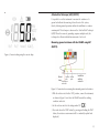
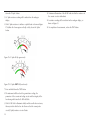
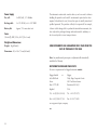
6.If the P Spike resistance is within acceptable limits as shown in Figure
17a (within the Green region on the Rp scale), release the ’Spike’
button.
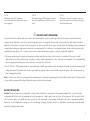
Figure 17a: P Spike OK (in green zone)
Figure 17b: P Spike NOT OK (in red zone)
7.Press and hold down the TEST button.
8.The instrument will then check for ground noise voltage, the
parameters of the current and voltage circuits and the integrity of the
fuse during which time the Rc LED will flash.
9.If the Rc LED fails to illuminate solidly and the needle does not move,
this may indicate that the fuse has blown or that the current probe
circuit (C Spike) resistance is out of limits.
18
10.Continuous illumination of the Rc LED indicates that the resistance of the current circuit is within limits.
11.A resistance reading will be indicated on the analogue display, as
shown in Figure 15.
12.On completion of measurement, release the TEST button.