1
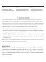
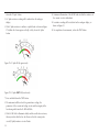
Connections for measuring four-terminal soil resistance
7.Press and hold the TEST button until a ‘100’ reading is obtained.
1.With the selector switch in the ‘OFF’ position, connect the instrument
as shown in Figure 7.
8.The instrument is now calibrated to the particular ICLAMP.
2.Set the selector switch to the 4 point resistance measurement setting
marked ‘4P’.
9.Switch the instrument to the OFF position.
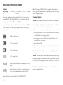
Measuring ground current with the ICLAMP (DET3TC)
3.Press and release the TEST button [by pressing and holding the TEST
button, the resistance measurement will be continually updated and
displayed].
4.The instrument will then check for ground noise, the parameters of the
current and voltage circuits and the integrity of the fuse
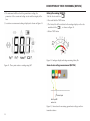
5.A resistance reading will be displayed on the LCD display, as shown in
Figure 6.
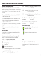
Calibrating the instrument to the ICLAMP (DET3TC)
Before proceeding with any measurement using the ICLAMP, it is
essential to calibrate the instrument to the particular ICLAMP using the
following procedure. This calibration should be repeated periodically.
1.With the selector switch in the ‘OFF’ position, connect ICLAMP to
instrument.
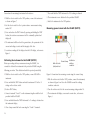
Earth electrode
(rod) under test
Current clamp
Installation
earthing
conductor
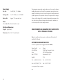
Figure 8: Connections for measuring current using the current clamp
2.Press and hold the TEST button and switch instrument ON to the ‘A’
setting on the selector switch.
1.With the selector switch in the ‘OFF’ position, connect the instrument,
as shown in Figure 8 and close the ICLAMP around the earthing
conductor under test.
3.Release TEST button,
2.Turn the selector switch to the current measuring setting marked ‘A’.
4.Connect terminals ‘X’ and ‘C’ on the instrument together with the lead
provided with the ICLAMP.
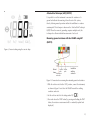
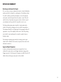
3.The instrument will display a measured current value, as shown in
Figure 9.
5.Press and hold down the TEST button until a ‘0’ reading is obtained on
the instrument display.
6.Close clamp around the lead connecting the ‘X’ and ‘C’ terminals.
14