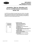
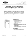
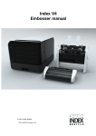
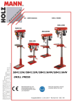
1
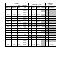
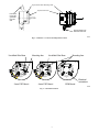
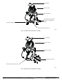
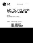
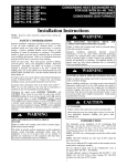
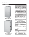
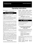
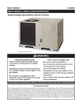
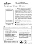
327752---401
327753---401
327754---401
Torsion---Flex Motor Mount for PSC Motors and
Rigid---Mount for ECM Motors Replacement Kit
Installation Instructions
NOTE: Read the entire instruction manual before starting the
installation.
!
SAFETY CONSIDERATIONS
FIRE, EXPLOSION, ELECTRICAL SHOCK
HAZARD
Improper
installation,
adjustment,
alteration,
service,
maintenance, or use can cause explosion, fire, electrical shock, or
other conditions which may cause death, personal injury, or
property damage. Consult a qualified installer, service agency, or
your distributor or branch for information or assistance. The
qualified installer or agency must use factory--authorized kits or
accessories when modifying this product. Refer to the individual
instructions packaged with the kits or accessories when installing.
Follow all safety codes. Wear safety glasses, protective clothing,
and work gloves. Have a fire extinguisher available. Read these
instructions thoroughly and follow all warnings or cautions
include in literature and attached to the unit. Consult local
building codes, the current editions of the National Fuel Gas
Code (NFGC) NFPA 54/ANSI Z223.1 and the National
Electrical Code (NEC) NFPA 70.
In Canada, refer to the current editions of the National Standards
of Canada CAN/CSA--B149.1 and .2 Natural Gas and Propane
Installation Codes, and Canadian Electrical Code CSA C22.1
Failure to follow this warning could result in personal
injury, death, or property damage.
The ability to properly perform service on this equipment
requires certain expertise, mechanical skills, tools, and
equipment. If you do not possess these, do not attempt to
perform any service on this equipment other than those
procedures recommended in the User’s Manual.
INTRODUCTION
This instruction covers the installation of replacement
torsion--flex motor mount or rigid motor mount on
non--condensing, 33.3--in. (868 mm) high, mid--efficiency hot
surface igniter furnaces.
DESCRIPTION AND USAGE
These kits can be utilized to replace a blower motor with an
approved service replacement motor instead of using the original
factory motor with the mounting arms directly attached to the
motor. This kit contains the following items (See Table 1).
Recognize safety information. This is the safety--alert symbol .
When you see this symbol on the unit and in instructions or
manuals, be alert to the potential for personal injury.
Understand the signal words DANGER, WARNING, and
CAUTION. These words are used with the safety--alert symbol.
DANGER identifies the most serious hazards which will result in
severe personal injury or death. WARNING signifies hazards
which could result in personal injury or death. CAUTION is
used to identify unsafe practices which may result in minor
personal injury or product and property damage. NOTE is used
to highlight suggestions which will result in enhanced
installation, reliability, or operation.
!
WARNING
Table 1 – Kit Contents
WARNING
FIRE, EXPLOSION, ELECTRICAL SHOCK
HAZARD
Failure to follow this warning could result in personal injury
or death.
Before installing or servicing unit, always turn off all gas and
electrical supplies to unit. There may be more than one
disconnect switch. Turn off accessory heater power, if
applicable.
Kit No. 327752-401
3 arm Torsion Flex Mount (PSC)
Self-locking ¼-20 hex nut
¼-20 x 1 ½” (38 mm) long hex bolt
Rubber grommets w/steel inserts
Instruction sheet
Qty.
1
1
1
3
1
Kit No. 327753-401
4 arm Torsion Flex Mount (PSC)
Self-locking ¼-20 hex nut
¼-20 x 1 ½” (38 mm) long hex bolt
Rubber grommets w/steel inserts
Instruction sheet
Qty.
1
1
1
4
1
Kit No. 327754-401
4 arm Rigid Mount (ECM)
Self-locking ¼-20 hex nut
¼-20 x 1 ½” (38 mm) long hex bolt
Rubber grommets
Instruction sheet
Qty.
1
1
1
4
1
A replacement motor, capacitor or ECM module is NOT included
in this kit and must be ordered separately if needed.
1
INSTALLATION
2. Loosen the setscrew that attaches the blower wheel to the
flat on the motor shaft.
3. Lay the blower assembly on its side and remove the 3 or 4
screws that secure the motor mounting arms to the blower
housing.
4. Remove the green ground lead from the side of the blower
housing. Note the location for re--assembly.
5. Slide the motor out of the blower wheel hub.
NOTE: If the motor will not slide out of the wheel, perform the
following steps:
6. Set the blower assembly, motor side down on a crate or
wooden box with a generous amount of padding inside.
7. Apply a small amount of lubricant between the shaft of the
motor and the hub of the blower wheel.
8. Tap the shaft of the motor using a block of wood, wooden
dowel pin or a 3/4--in. (19 mm) brass drift pin. DO NOT
HAMMER DIRECTLY ON THE SHAFT OF THE
MOTOR. The motor shaft may “mushroom” and prevent
the motor from being removed from the wheel.
You may also use a commercially available tool that
clamps on the blower wheel hub and pushes the motor
shaft out of the wheel.
When the motor drops into the box or crate, remove it
from the box and set it aside.
Step 1 — Remove the Existing Blower Assembly
1. Turn off electric supplies to unit and thermostat. More
than 1 disconnect may be required to disconnect power to
unit.
2. Remove exterior door by loosening knurled knob on door
and pulling forward.
3. Turn off gas at external supply shutoff and turn electric
switch on gas control “OFF”.
!
CAUTION
CUT HAZARD
Failure to follow this caution may result in personal injury.
Sheet metal parts may have sharp edges or burrs. Use care
and wear appropriate protective clothing, safety glasses and
gloves when handling parts and servicing furnaces.
4. On downflow or horizontal positions where the vent
connector passes in front of the blower access panel,
disconnect and remove vent connector from vent elbow.
NOTE: Support vent connector with temporary metal strap to
prevent damage to vent connector or vent connector elbows.
5. Remove the 2 screws that secure the blower access door
and set door aside.
6. Remove the screw that secures the blower door switch to
the front edge of the heat exchanger cell panel. Do not
disconnect blower door switch wires.
7. Remove the wiring harness from the recess in the blower
shelf.
8. Remove the blower leads that connect the motor to the
furnace control board and capacitor.
!
!
CAUTION
UNIT DAMAGE HAZARD
Failure to follow this caution may result improper unit
functioning.
The blower wheel should not be dropped, as balance will be
affected.
Step 3 — Assemble the Replacement Motor Mount
and Motor
CAUTION
1. Verify that the grommets and inserts (if used) are inserted
in the mounting legs correctly per Fig. 1.
2. Place the motor mount around the mid--section of the
motor. Position the motor around the mid--section of the
motor as shown in Fig. 1.
NOTE: Failure to correctly position the motor may result in
unwanted noise or vibration in the blower assembly.
3. Slightly tighten the hex nut and bolt to allow the motor
mount to slide up and down the shell of the motor.
4. Rotate the motor in the band for correct alignment--
UNIT DAMAGE HAZARD
Failure to follow this caution may result in improper unit
functioning.
Mark wires prior to disassembly to aid re--assembly. Wiring
errors could result in improper or dangerous operation
Note: Pull motor lead terminals straight out of control
connectors instead of pulling on wires to prevent damage to
the relay terminal on top of the control relays.
9. On some Variable Speed (ECM) furnace models,
disconnect the wires from the motor.
10. Remove the 2 screws that secure the control assembly to
the blower shelf inside the blower compartment. Do not
discard.
11. Move the control aside. Secure control assembly aside
with a scrap length of wire or tape.
12. Using a 5/16--nut driver remove the blower housing
mounting screws that secure the blower assembly to the
blower shelf.
13. Slide the blower assembly forward, out of the blower
compartment.
For 3--arm PSC Motors: With one mounting leg
positioned at 12 o’clock, rotate the motor so that the GE
logo (on the undrilled oiler boss) on the end of the motor
is positioned slightly to the left (5 degrees) of the
mounting leg (See Fig. 2).
For 4--arm PSC Motors: Position GE logo (on the
undrilled oiler boss) on the end of the motor centered
between two of the mounting arms (See Fig. 2).
For ECM Motors: Position control and power connectors
centered between two of the mounting arms (See Fig. 2).
Step 2 — Remove Blower Motor
Recheck alignment from Step 2 and torque mounting band
bolt and nut to a minimum of 80 in--lbs.
1. Clean blower wheel with a small paintbrush or flux brush.
Be careful not to dislodge balance clips attached to the
blower wheel blades.
Step 4 — Assemble the Blower
1. Insert blower motor shaft into hub of blower wheel.
2
Step 6 — System Check-- Out
2. Check to see the blower wheel is not jammed against the
blower housing before installing motor mounting screws.
3. Align the motor mounting arms as shown in Fig. 1. See
Table 1 for the correct Dimension “A”, as shown in Fig. 1
1. Set thermostat to “OFF”. Manually close blower door
switch. Initiate component test through circuit board by
referring to “Component Test” on status code label on
blower access door for complete test sequence
information.
2. If any status codes are flashed, refer to status code label on
unit blower door.
3. Release the blower door switch.
4. Install blower access panel on furnace and secure with the
2 existing screws.
5. Turn thermostat fan switch to “ON”, to initiate a call for
continuous fan operation.
6. Verify that the blower wheel does not rub against the
housing.
7. On Downflow or Horizontal models, install the vent
connector if the connector was removed. Verify that no
other connectors or joints were damaged during
disassembly.
8. Turn gas ON at external shut off and at electric switch on
gas valve.
9. Set thermostat to call for heat.
10. Allow unit to initiate a complete call for heat cycle.
NOTE: Blower motor failure may have been caused by one or
more of the following conditions. As part of the system
check--out, verify that the following conditions are not affecting
the operation of the furnace:
PSC motors are properly positioned if the undrilled oiler
boss is pointing toward the rear of the blower housing. See
Fig. 2
ECM motors are properly positioned if the connectors on
the motor modules are pointing away from the blower
discharge air opening. See Fig 2
NOTE: See Fig 3 and Fig 4 for additional blower assembly
information.
4. Install blower motor mounting screws in previously used
holes in blower housing. Torque to 30 to 50 in.-- lbs. Do
not over--tighten.
NOTE: Over tightening screws on mounting legs may result in
stripped out screw holes. If a screw hole is stripped, remove all
screws and rotate the mounting band to the next set of screw
holes provided in the blower assembly.
5. Attach the green ground wire from the motor to the sheet
metal of the blower housing on furnaces with PSC motors.
ECM motors are grounded through the 5--pin connector
harness in the same location.
!
WARNING
ELECTRICAL OPERATION HAZARD
S
High external static pressure: Dirty filter or high
pressure drop filter. Undersized filter grills. Restricted
or undersized duct systems. Dirty evaporator coil.
S
Noise: High air flow due to high external static
pressure. Incorrect speed tap selected for heating
temperature rise or cooling airflow. Improper motor
positioning in mounting band.
Failure to follow this warning could result in personal
injury or death.
The furnace must be grounded to minimize personal injury
if an electrical short should occur.
6. Center the blower wheel in the opening of the blower
housing. Align the set--screw on the flat portion of the
blower shaft. Torque set screw to a minimum of 140
in.--lbs to a maximum of 160 in.--lbs
Vibration: Unit not set flat or level. Blower wheel bent
or out of balance. Flexible duct connectors not used
with sheet metal ducts. Improper motor positioning in
mounting band.
For additional information, and a complete sequence of furnace
operation, refer to furnace Installation, Start--Up and Operating
Instructions.
11. After System Check--out is complete, set thermostat below
room temperature.
12. Verify that burner shuts down and blower completes
selected off delay furnace time delay. Verify furnace
operates properly and set thermostat to desired room
temperature.
13. Re--install outer door.
S
Step 5 — Install Blower Assembly in Furnace
1. Insert the flanges of the blower housing into the rail of the
furnace blower deck
2. Slide the blower assembly into the furnace until it is fully
seated in the blower compartment.
3. Install the 5/16” screws to blower deck in the furnace
through the opening in the flange on the blower housing.
4. Tighten the screws with a 5/16” nut driver.
5. Install the control assembly to the front of the blower shelf
of the furnace.
6. Connect the electrical leads to the terminals on the control
assembly. If wires were not marked during disassembly,
refer to the wiring label on the blower access door.
On ECM models, plug 5--pin and 16--pin connectors into
the motor module. Both connectors are indexed for correct
orientation.
7. Install the wiring harness in the recess of the front edge of
the heat exchanger cell panel.
8. Secure the wiring harness by installing the blower door
switch bracket to the front edge of the heat exchanger cell
panel. Use caution when installing the switch to prevent
wires from being pinched.
9. Spin blower wheel by hand to verify that wheel does not
rub against housing.
3
VARIABLE SPEED
(ECM Motor)
In. (mm)
PSC MOTOR
“A” Dimension --- In. (mm)
FURNACE
Model Size
Model Size
Casing
Width
In. (mm)
Wheel Dia x
Width
In. (mm)
HP
3-Speed
4-Speed
024045
045-08
14 (356)
10x6
(254x152)
1/5
0.94 (24)
1.18 (30)
036045
045-12
14 (356)
10x6
(254x152)
1/3
0.68 (17)
0.68 (17)
024070
070-08
14 (356)
10x6
(254x152)
1/5
0.94 (24)
1.18 (30)
036070
070-12
14 (356)
10x6
(254x152)
1/3
0.68 (17)
0.68 (17)
1.88 (48)
048070
070-16
17 (432)
11x8
(279x203)
1/2
1.00 (25)
1.00 (25)
1.65 (42)
042090
090-14
17 (432)
10x8
(254x203)
1/3
0.68 (17)
0.68 (17)
048090
090-16
17 (432)
10x8
(254x203)
048090
090-16
21 (533)
10x10
(254x254)
1/2
1.00 (25)
1.00 (25)
1.65 (42)
060090
090-20
21 (533)
11x11
(279x279)
3/4
1.00 (25)
1.00 (25)
1.75 (45)
036110
110-12
17 (432)
10x8
(254x203)
1/3
0.68 (17)
0.68 (17)
048110
110-16
21 (533)
10x10
(254x254)
1/2
1.00 (25)
1.00 (25)
060110
110-20
21 (533)
12x11
(305x279)
066110
110-66
21 (533)
11x11
(279x279)
3/4
1.00 (25)
1.00 (25)
048135
135-16
21 (533)
10x10
(254x254)
1/2
1.00 (25)
1.00 (25)
060135
135-20
24 (610)
11x11
(279x279)
3/4
1.00 (25)
060155
155-20
24 (610)
11x11
(279x279)
3/4
1.00 (25)
4
5-Speed
HP
“A” dimension
1/2
.97 (25)
1/2
.97 (25)
1
2.01 (51)
1
2.01 (51)
1.00 (25)
1
2.01 (51)
1.00 (25)
1
2.01 (51)
1.88 (48)
1.65 (42)
1.75
Replacement Motor Mounting Band
A
Replacement motor
Push steel
inserts into
grommets
from this
side.
Push grommets into
holes from this side.
A08567
Fig. 1 -- Dimension “A” Motor Mounting Band Location
Un-drilled Oiler Boss
Mounting Arm
Un-drilled Oiler Boss
Mounting Arm
Electrical
connectors
3-arm PSC Mount
4-arm PSC Mount
ECM Mount
A08568
Fig. 2 -- Orientation of Motor
5
Cut-off plate
Blower wheel
Blower housing
PSC Blower Motor (Some
models use 4 mounting
arms)
Capacitor and Strap
Attach green ground wire here
A08569
Fig. 3 -- Expanded View of PSC Blower Assembly
Cut-off plate
Blower wheel
Blower housing
ECM blower motor
Attach green ground wire here
A08570
Fig. 4 -- Expanded View of ECM Blower Assembly
Copyright 2008 CAC / BDP S 7310 W. Morris St. S Indianapolis, IN 46231
Printed in U.S.A.
Edition Date: 11/08
Manufacturer reserves the right to change, at any time, specifications and designs without notice and without obligations.
6
Catalog No: IIK---327752---01
Replaces: IIK--310A--45--11, 58ST--10SI