1
Step 6 — System Check-- Out
2. Check to see the blower wheel is not jammed against the
blower housing before installing motor mounting screws.
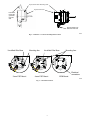
3. Align the motor mounting arms as shown in Fig. 1. See
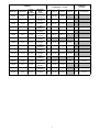
Table 1 for the correct Dimension “A”, as shown in Fig. 1
1. Set thermostat to “OFF”. Manually close blower door
switch. Initiate component test through circuit board by
referring to “Component Test” on status code label on
blower access door for complete test sequence
information.
2. If any status codes are flashed, refer to status code label on
unit blower door.
3. Release the blower door switch.
4. Install blower access panel on furnace and secure with the
2 existing screws.
5. Turn thermostat fan switch to “ON”, to initiate a call for
continuous fan operation.
6. Verify that the blower wheel does not rub against the
housing.
7. On Downflow or Horizontal models, install the vent
connector if the connector was removed. Verify that no
other connectors or joints were damaged during
disassembly.
8. Turn gas ON at external shut off and at electric switch on
gas valve.
9. Set thermostat to call for heat.
10. Allow unit to initiate a complete call for heat cycle.
NOTE: Blower motor failure may have been caused by one or
more of the following conditions. As part of the system
check--out, verify that the following conditions are not affecting
the operation of the furnace:
PSC motors are properly positioned if the undrilled oiler
boss is pointing toward the rear of the blower housing. See
Fig. 2
ECM motors are properly positioned if the connectors on
the motor modules are pointing away from the blower
discharge air opening. See Fig 2
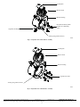
NOTE: See Fig 3 and Fig 4 for additional blower assembly
information.
4. Install blower motor mounting screws in previously used
holes in blower housing. Torque to 30 to 50 in.-- lbs. Do
not over--tighten.
NOTE: Over tightening screws on mounting legs may result in
stripped out screw holes. If a screw hole is stripped, remove all
screws and rotate the mounting band to the next set of screw
holes provided in the blower assembly.
5. Attach the green ground wire from the motor to the sheet
metal of the blower housing on furnaces with PSC motors.
ECM motors are grounded through the 5--pin connector
harness in the same location.
!
WARNING
ELECTRICAL OPERATION HAZARD
S
High external static pressure: Dirty filter or high
pressure drop filter. Undersized filter grills. Restricted
or undersized duct systems. Dirty evaporator coil.
S
Noise: High air flow due to high external static
pressure. Incorrect speed tap selected for heating
temperature rise or cooling airflow. Improper motor
positioning in mounting band.
Failure to follow this warning could result in personal
injury or death.
The furnace must be grounded to minimize personal injury
if an electrical short should occur.
6. Center the blower wheel in the opening of the blower
housing. Align the set--screw on the flat portion of the
blower shaft. Torque set screw to a minimum of 140
in.--lbs to a maximum of 160 in.--lbs
Vibration: Unit not set flat or level. Blower wheel bent
or out of balance. Flexible duct connectors not used
with sheet metal ducts. Improper motor positioning in
mounting band.
For additional information, and a complete sequence of furnace
operation, refer to furnace Installation, Start--Up and Operating
Instructions.
11. After System Check--out is complete, set thermostat below
room temperature.
12. Verify that burner shuts down and blower completes
selected off delay furnace time delay. Verify furnace
operates properly and set thermostat to desired room
temperature.
13. Re--install outer door.
S
Step 5 — Install Blower Assembly in Furnace
1. Insert the flanges of the blower housing into the rail of the
furnace blower deck
2. Slide the blower assembly into the furnace until it is fully
seated in the blower compartment.
3. Install the 5/16” screws to blower deck in the furnace
through the opening in the flange on the blower housing.
4. Tighten the screws with a 5/16” nut driver.
5. Install the control assembly to the front of the blower shelf
of the furnace.
6. Connect the electrical leads to the terminals on the control
assembly. If wires were not marked during disassembly,
refer to the wiring label on the blower access door.
On ECM models, plug 5--pin and 16--pin connectors into
the motor module. Both connectors are indexed for correct
orientation.
7. Install the wiring harness in the recess of the front edge of
the heat exchanger cell panel.
8. Secure the wiring harness by installing the blower door
switch bracket to the front edge of the heat exchanger cell
panel. Use caution when installing the switch to prevent
wires from being pinched.
9. Spin blower wheel by hand to verify that wheel does not
rub against housing.
3