1
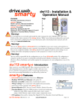
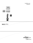
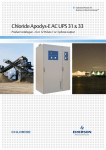
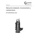
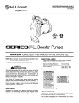
User guide
SRC 311 - Pumpdrive with SmartRun™
functionality, dedicated for waste water
pump station
Table of Contents
Table of Contents
Introduction and Safety.........................................................................................................................2
SRC 311................................................................................................................................................2
Electromagnetic Compatibility..........................................................................................................4
Important Safety Information.............................................................................................................4
Installation...............................................................................................................................................7
Mechanical Installation.......................................................................................................................7
Mechanical Dimensions and Mounting.........................................................................................7
Guidelines for Mounting..................................................................................................................8
Removing the Terminal Cover........................................................................................................9
Electrical Installation.........................................................................................................................10
Grounding the Drive......................................................................................................................10
Wiring Precautions.........................................................................................................................11
Incoming Power Connection........................................................................................................11
Drive and Motor Connection........................................................................................................12
Motor Terminal Box Connections................................................................................................12
Control Terminal Wiring................................................................................................................13
System Description..............................................................................................................................15
Managing the Keypad......................................................................................................................15
Serial Communications.....................................................................................................................15
Modbus RTU Communications.....................................................................................................16
Technical Reference............................................................................................................................19
Environmental....................................................................................................................................19
Input voltage......................................................................................................................................19
Maximum supply ratings for UL- compliance................................................................................19
Output power and current ratings..................................................................................................20
SRC 311 - Pumpdrive with SmartRun™ functionality, dedicated for waste water pump station User guide
1
Introduction and Safety
Introduction and Safety
SRC 311
Frame Sizes 2 and 3
1
2 SmartRun
A
STOP
15kW
9 400V
3
3ph
4
5
8
PE L1 L2 L3 7
M
6
1.
2.
3.
4.
Mechanical mounting, see Mechanical Installation (page 7).
Display (Status, Diagnostics, and Programming).
Keypad Operation see Managing the Keypad (page 15).
Control Terminal Configuration based on factory settitngs Safe Torque Off (STO) Link the terminals as
shown above through the emergency stop circuit contacts.
• Close the switch to run (enable)
• Open the switch to stop (disable)
5.
2
Motor Cable Sizes, see Output power and current ratings (page 20).
SRC 311 - Pumpdrive with SmartRun™ functionality, dedicated for waste water pump station User guide
Introduction and Safety
6.
Motor Connections, Check for Star or Delta connection according to the motor voltage rating.
Motor Nameplate Details:
• Motor Rated Voltage: P1-07
• Motor Rated Current: P1-08
• Motor Rated Frequency: P1-09
• Motor Rated Speed (Optional): P1-10
7.
8.
Fuses or MCB, see Output power and current ratings (page 20).
AC Supply Connection, see Output power and current ratings (page 20).
• 200 – 240 Volts + / - 10%: 1 / 3 Phase
• 380 – 380 Volts + / - 10%: 3 Phase
9.
Applies to Switched version only In-built Controls: Power On / Off
Frame Sizes 4 to 6
1
2
SmartRun
A
STOP
15kW
400V
3ph
3
4
Supply Voltage
5
8
PE
L1 L2 L3
7
M
6
SRC 311 - Pumpdrive with SmartRun™ functionality, dedicated for waste water pump station User guide
3
Introduction and Safety
Electromagnetic Compatibility
All SRC 311 are designed with high standards of EMC in mind. All versions suitable for
operation on Single Phase 230 volt and Three Phase 400 volt supplies and intended for
use within the European Union are fitted with an internal EMC filter. This EMC filter is
designed to reduce the conducted emissions back into the supply via the power cables for
compliance with harmonised European standards. It is the responsibility of the installer to
ensure that the equipment or system into which the product is incorporated complies with
the EMC legislation of the country of use. Within the European Union, equipment into
which this product is incorporated must comply with the EMC Directive 2004/108/EC.
When using an SRC 311 with an internal or optional external filter, compliance with the
following EMC Categories, as defined by EN61800-3:2004 can be achieved:
Drive Type / Rating
EMC Category
Cat C1
Cat C2
Cat C3
1 Phase, 230 Volt Input
SRC311-X-2-XXXXX-XX
No additional filtering required
Use shielded motor cable
3 Phase, 400 Volt Input
SRC311-X-4-XXXXX-XX
Use External Filter
Note
For motor cable lengths greater than 100 m, an output dv / dt filter must be used,
please refer to the local Sales Partner for further details
No additional filtering required
Use screened motor cable
Important Safety Information
DANGER: Indicates a risk of electric shock, which, if not avoided, could result in damage to
the equipment and possible injury or death.
DANGER: Indicates a potentially hazardous situation other than electrical, which if not
avoided, could result in damage to property.
4
SRC 311 - Pumpdrive with SmartRun™ functionality, dedicated for waste water pump station User guide
Introduction and Safety
This variable speed drive product is intended for professional incorporation into complete
equipment or systems as part of a fixed installation. If installed incorrectly it may present a
safety hazard. The SRC 311 uses high voltages and currents, carries a high level of stored
electrical energy, and is used to control mechanical plant that may cause injury. Close
attention is required to system design and electrical installation to avoid hazards in either
normal operation or in the event of equipment malfunction. Only qualified electricians are
allowed to install and maintain this product.
System design, installation, commissioning and maintenance must be carried out only by
personnel who have the necessary training and experience. They must carefully read this
safety information and the instructions in this Guide and follow all information regarding
transport, storage, installation and use of the SRC 311, including the specified
environmental limitations.
Do not perform any flash test or voltage withstand test on the SRC 311. Any electrical
measurements required should be carried out with the SRC 311 disconnected.
Electric shock hazard! Disconnect and ISOLATE the SRC 311 before attempting any work on it.
High voltages are present at the terminals and within the drive for up to 10 minutes after
disconnection of the electrical supply. Always ensure by using a suitable multimeter that no
voltage is present on any drive power terminals prior to commencing any work.
Where supply to the drive is through a plug and socket connector, do not disconnect until 10
minutes have elapsed after turning off the supply.
Ensure correct earthing connections. The earth cable must be sufficient to carry the maximum
supply fault current which normally will be limited by the fuses or MCB. Suitably rated fuses
or MCB should be fitted in the mains supply to the drive, according to any local legislation or
codes.
Do not carry out any work on the drive control cables whilst power is applied to the drive or to
the external control circuits.
SRC 311 - Pumpdrive with SmartRun™ functionality, dedicated for waste water pump station User guide
5
Introduction and Safety
Within the European Union, all machinery in which this product is used must comply with
Directive 98/37/EC, Safety of Machinery. In particular, the machine manufacturer is
responsible for providing a main switch and ensuring the electrical equipment complies with
EN60204-1.
The level of integrity offered by the SRC 311 control input functions (excluding the ‘Safe
Torque Free Input’) – for example stop/start, forward/reverse and maximum speed, is not
sufficient for use in safety-critical applications without independent channels of protection.
All applications where malfunction could cause injury or loss of life must be subject to a risk
assessment and further protection provided where needed.
The driven motor can start at power up if the enable input signal is present.
The STOP function does not remove potentially lethal high voltages. ISOLATE the drive and
wait 10 minutes before starting any work on it. Never carry out any work on the Drive, Motor
or Motor cable whilst the input power is still applied.
The SRC 311 can be programmed to operate the driven motor at speeds above or below the
speed achieved when connecting the motor directly to the mains supply. Obtain
confirmation from the manufacturers of the motor and the driven machine about suitability
for operation over the intended speed range prior to machine start up.
Do not activate the automatic fault reset function on any systems whereby this may cause a
potentially dangerous situation.
The SRC 311 has an Ingress Protection rating of IP55, and are intended for indoor use only
When mounting the drive, ensure that sufficient cooling is provided. Do not carry out drilling
operations with the drive in place, dust and swarf from drilling may lead to damage.
The entry of conductive or flammable foreign bodies should be prevented. Flammable
material should not be placed close to the drive
Relative humidity must be less than 95% (non-condensing).
Ensure that the supply voltage, frequency and no. of phases (1 or 3 phase) correspond to the
rating of the SRC 311 as delivered.
Never connect the mains power supply to the Output terminals U, V, W.
Do not install any type of automatic switchgear between the drive and the motor
Wherever control cabling is close to power cabling, maintain a minimum separation of 100
mm and arrange crossings at 90 degrees Ensure that all terminals are tightened to the
appropriate torque setting
Do not attempt to carry out any repair of the SRC 311. In the case of suspected fault or
malfunction, contact your local Sales Partner for further assistance.
6
SRC 311 - Pumpdrive with SmartRun™ functionality, dedicated for waste water pump station User guide
Installation
Installation
Mechanical Installation
General
• The SRC 311 should be mounted in a vertical position only on a flat, flame resistant
vibration free mounting using the integral holes.
• The SRC 311 must be installed in a pollution degree 1 or 2 environment only.
• Do not mount flammable material close to the SRC 311
• Ensure that the minimum cooling air gaps, as detailed in section 0 are left clear
• Ensure that the ambient temperature range does not exceed the permissible limits for
the SRC 311 given in Environmental (page 19).
• Provide suitable clean, moisture and contaminant free cooling air sufficient to fulfil the
cooling requirements of the SRC 311 according to Environmental (page 19).
Before Installation
• Carefully Unpack the SRC 311 and check for any signs of damage. Notify the shipper
immediately if any exist.
• Check the drive rating label to ensure it is of the correct type and power requirements
for the application.
• Store the SRC 311 in its box until required. Storage should be clean and dry and within
the temperature range –40°C to +60°C
UL-Compliant Installation
Note the following for UL-compliant installation:
• The drive can be operated within an ambient temperature range as stated in
Environmental (page 19).
• Installation in a pollution degree 2 environmant is permissible
• UL Listed ring terminals / lugs must be used for all bus bar and grounding connections
Mechanical Dimensions and Mounting
Frame Sizes 2 - 3
C
A
B
H
I
D
G
F
Driv A
e
Size mm in
2
257 10.
.0 12
E
B
C
D
E
F
G
H
I
mm in
mm in
mm in
mm in
mm in
mm in
mm in
mm in
220 8.6
.0 7
200 7.8
.0 7
28.
5
238 9.3
7
188 7.4
.0 0
176 6.9
.0 3
4.2
8.5
1.1
2
SRC 311 - Pumpdrive with SmartRun™ functionality, dedicated for waste water pump station User guide
0.1
7
0.3
3
7
Installation
Driv A
e
Size mm in
3
310 12.
.0 20
B
C
D
E
F
G
H
I
mm in
mm in
mm in
mm in
mm in
mm in
mm in
mm in
276 10.
.5 89
251 9.9
.5 0
33.
4
256 10.
08
210 8.2
.5 9
197 7.7
.5 8
4.2
8.5
1.3
1
0.1
7
0.3
3
Control Terminal Torque Settings: All Sizes: 0.8 Nm (7 lb-in)
Power Terminal Torque Settings: All Sizes: 1 Nm (8.85 lb-in)
Frame Size 4 - 6
H
I
A
C
B
D
F
G
E
Driv A
e
Size mm in
B
C
D
E
F
G
H
I
mm in
mm in
mm in
mm in
mm in
mm in
mm in
mm in
4
440 17.
32
418 16.
46
423 16.
65
8
0.3
15
230 9.0
6
173 6.8
1
110 4.3
3
4.2
5
0.1
67
7.5
0.2
95
5
540 21.
26
515 20.
28
520 20.
47
8
0.3
15
270 10.
63
235 9.2
5
175 6.8
9
4.2
5
0.1
67
7.5
0.2
95
6
865 34.
06
830 32.
68
840 33.
07
10
0.3
94
340 13.
39
290 11.
42
200 7.8
7
5.5
0.2
17
11
0.2
95
Control Terminal Torque Settings:
All Sizes
0.8 Nm (7 lb-in)
Power Terminal Torque Settings:
Frame Size 4:
1.2 – 1.5 Nm
Frame Size 5:
2.5 – 4.5 Nm
Frame Size 6:
8 Nm
Guidelines for Mounting
• Before mounting the drive, ensure that the chosen location meets the environmental
condition requirements for the drive shown in Environmental (page 19).
• The drive must be mounted vertically, on a suitable flat surface
8
SRC 311 - Pumpdrive with SmartRun™ functionality, dedicated for waste water pump station User guide
Installation
• The minimum mounting clearances as shown in the table below must be observed
• The mounting site and chosen mountings should be sufficient to support the weight of
the drives
Drive Size
X - Above and Below
Y - Either Side
mm
in
mm
in
4
200
7.87
10
0.394
5
200
7.87
10
0.394
6
200
7.87
10
0.394
Typical drive heat losses are 3% of operating load conditions.
Above are guidelines only and the operating ambient temperature of the drive MUST be
maintained at all times.
Removing the Terminal Cover
Frame Size 4
Frame Size 5
Using a suitable flat blade screwdriver, rotate the two
retaining screws indicated until the screw slot is vertical.
Using a suitable flat blade screwdriver, rotate the four
retaining screws indicated until the screw slot is vertical.
SRC 311 - Pumpdrive with SmartRun™ functionality, dedicated for waste water pump station User guide
9
Installation
Terminal Cover Release Screws
Frame Size 6
Remove the two screws indicated, lift the cover forwards and off. To refit the cover, slide the top locating lugs
upwards under the top cover, then re-fasten the lower cover screws
Electrical Installation
Grounding the Drive
DANGER: This manual is intended as a guide for proper installation. Xylem Water Solution
AB cannot assume responsibility for the compliance or the non-compliance to any code,
national, local or otherwise, for the proper installation of this drive or associated
equipment. A hazard of personal injury and/or equipment damage exists if codes are
ignored during installation.
DANGER: This SRC 311 contains high voltage capacitors that take time to discharge after
removal of the main supply. Before working on the drive, ensure isolation of the main
supply from line inputs. Wait ten (10) minutes for the capacitors to discharge to safe
voltage levels. Failure to observe this precaution could result in severe bodily injury or loss
of life.
DANGER: Only qualified electrical personnel familiar with the construction and operation
of this equipment and the hazards involved should install, adjust, operate, or service this
equipment. Read and understand this manual and other applicable manuals in their
entirety before proceeding. Failure to observe this precaution could result in severe bodily
injury or loss of life.
10
SRC 311 - Pumpdrive with SmartRun™ functionality, dedicated for waste water pump station User guide
Installation
Grounding Guidelines
The ground terminal of each SRC 311 should be individually connected DIRECTLY to the
site ground bus bar (through the filter if installed). SRC 311 ground connections should not
loop from one drive to another, or to, or from any other equipment. Ground loop
impedance must confirm to local industrial safety regulations. To meet UL regulations, UL
approved ring crimp terminals should be used for all ground wiring connections.
The drive Safety Ground must be connected to system ground. Ground impedance must
conform to the requirements of national and local industrial safety regulations and/or
electrical codes. The integrity of all ground connections should be checked periodically.
Protective Earth Conductor
The Cross sectional area of the PE Conductor must be at least equal to that of the
incoming supply conductor.
Safety Ground
This is the safety ground for the drive that is required by code. One of these points must be
connected to adjacent building steel (girder, joist), a floor ground rod, or bus bar.
Grounding points must comply with national and local industrial safety regulations and/or
electrical codes.
Motor Ground
The motor ground must be connected to one of the ground terminals on the drive.
Ground Fault Monitoring
As with all inverters, a leakage current to earth can exist. The SRC 311 is designed to
produce the minimum possible leakage current whilst complying with worldwide
standards. The level of current is affected by motor cable length and type, the effective
switching frequency, the earth connections used and the type of RFI filter installed. If an
ELCB (Earth Leakage Circuit Breaker) is to be used, the following conditions apply:
• A Type B Device must be used
• The device must be suitable for protecting equipment with a DC component in the
leakage current
• Individual ELCBs should be used for each SRC 311
Shield Termination (Cable Screen)
The safety ground terminal provides a grounding point for the motor cable shield. The
motor cable shield connected to this terminal (drive end) should also be connected to the
motor frame (motor end). Use a shield terminating or EMI clamp to connect the shield to
the safety ground terminal.
Wiring Precautions
Connect the SRC 311 according to Drive and Motor Connection (page 12) and Motor
Terminal Box Connections (page 12), ensuring that motor terminal box connections are
correct. There are two connections in general: Star and Delta. It is essential to ensure that
the motor is connected in accordance with the voltage at which it will be operated. For
more information, refer to Motor Terminal Box Connections (page 12).
It is recommended that the power cabling should be 4-core PVC-insulated screened cable,
laid in accordance with local industrial regulations and codes of practice.
Incoming Power Connection
• For a single phase supply, power should be connected to L1/L, L2/N.
• For 3 phase supplies power should be connected to L1, L2, and L3. Phase sequence is
not important.
• For compliance with CE and C Tick EMC requirements, a symmetrical shielded cable is
recommended.
SRC 311 - Pumpdrive with SmartRun™ functionality, dedicated for waste water pump station User guide
11
Installation
• A fixed installation is required according to IEC61800-5-1 with a suitable disconnecting
device installed between the SRC 311 and the AC Power Source. The disconnecting
device must conform to the local safety code / regulations (e.g. within Europe,
EN60204-1, Safety of machinery).
• The cables should be dimensions according to any local codes or regulations.
Guideline dimensions are given in Output power and current ratings (page 20).
• Suitable fuses to provide wiring protection of the input power cable should be
installed in the incoming supply line, according to the data in Output power and
current ratings (page 20). The fuses must comply with any local codes or regulations
in place. In general, type gG (IEC 60269) or UL type T fuses are suitable; however in
some cases type aR fuses may be required. The operating time of the fuses must be
below 0.5 seconds.
• Where allowed by local regulations, suitably dimensioned type B MCB circuit breakers
of equivalent rating may be utilized in place of fuses, providing that the clearing
capacity is sufficient for the installation.
• When the power supply is removed from the drive, a minimum of 30 seconds should
be allowed before re-applying the power. A minimum of 10 minutes should be
allowed before removing the terminal covers or connection.
• The maximum permissible short circuit current at the SRC 311 Power terminals as
defined in IEC60439-1 is 100kA.
• An optional Input Choke is recommended to be installed in the supply line for drives
where any of the following conditions occur:
• The incoming supply impedance is low or the fault level / short circuit current is high
• The supply is prone to dips or brown outs
• An imbalance exists on the supply (3 phase drives)
• The power supply to the drive is via a busbar and brush gear system (typically
overhead Cranes).
• In all other installations, an input choke is recommended to ensure protection of the
drive against power supply faults.
• SRC 311 models in frame sizes 4 to 6 are factory fitted with an Input choke as standard.
Drive and Motor Connection
• The motor should be connected to the SRC 311 U, V, and W terminals using a suitable
3 or 4 core cable. Where a 3 core cable is utilised, with the shield operating as an earth
conductor, the shield must have a cross sectional area at least equal to the phase
conductors when they are made from the same material. Where a 4 core cable is
utilized, the earth conductor must be of at least equal cross sectional area and
manufactured from the same material as the phase conductors.
• The motor earth must be connected to one of the SRC 311 earth terminals.
• For compliance with the European EMC directive, a suitable screened (shielded) cable
should be used. Braided or twisted type screened cable where the screen covers at
least 85% of the cable surface area, designed with low impedance to HF signals are
recommended as a minimum. Installation within a suitable steel or copper tube is
generally also acceptable.
• The cable screen should be terminated at the motor end using an EMC type gland
allowing connection to the motor body through the largest possible surface area
• Where drives are mounted in a steel control panel enclosure, the cable screen may be
terminated directly to the control panel using a suitable EMC clamp or gland, as close
to the drive as possible.
• For IP55 drives, connect the motor cable screen to the internal ground clamp
Motor Terminal Box Connections
Most general purpose motors are wound for operation on dual voltage supplies.
12
SRC 311 - Pumpdrive with SmartRun™ functionality, dedicated for waste water pump station User guide
Installation
This is indicated on the nameplate of the motor This operational voltage is normally
selected when installing the motor by selecting either STAR or DELTA connection. STAR
always gives the higher of the two voltage ratings.
230
230 / 400
400
400 / 690
400
230 / 400
Delta
Star
Control Terminal Wiring
• All analog signal cables should be suitably shielded. Twisted pair cables are
recommended.
• Power and Control Signal cables should be routed separately where possible, and
must not be routed parallel to each other
• Maximum control terminal tightening torque is 0.5Nm
Control Terminals Connection Diagram
Control Terminal Connections
Main Terminal Strip
SRC 311 - Pumpdrive with SmartRun™ functionality, dedicated for waste water pump station User guide
13
Installation
1
+24V
+ 24V User Output (Input)
100mA User Output or +24V
back up supply.
2
DI 1
Input 1
Digital 8 – 30 Volt DC
3
DI 2
Input 2
Digital 8 – 30 Volt DC
4
DI 3
Input 3
Digital 8 – 30 Volt DC
5
+10V
+ 10 Volt User Output
10mA
6
AI 1
Input 4
Analog Input 1, -10 to +10V, 0 /
4 to 20mA
7
0V
0 Volt Common
8
AO1
Output 1
9
0V
0 Volt Common
10
AI 2
Input 5
0 / 4 to 20mA
11
AO2
Output 2
Digital Output, 0 to 10V
12
STO+
Drive hardware inhibit
“Safe” 24V input - must be
linked to ext +24 Volt (18 – 30
Volt) DC to enable power stage
13
STO-
Inhibit 0V input
0V return for the 24V “Safe”
(STO)
1st Analog 4 to 20mA
Additional Terminal Strip
14
14
RL1-C
Relay Output 1 Common
Relay contacts, 250V AC, 30V
DC, 5A
15
RL1-NO
Relay Output 1 NO
Relay contacts, 250V AC, 30V
DC, 5A
16
RL1-NC
Relay Output 1 NC
Relay contacts, 250V AC, 30V
DC, 5A
17
RL2-A
Relay Output 2 Common
Relay contacts, 250V AC, 30V
DC, 5A
18
RL2-B
Relay Output 2 NO
Relay contacts, 250V AC, 30V
DC, 5A
SRC 311 - Pumpdrive with SmartRun™ functionality, dedicated for waste water pump station User guide
System Description
System Description
Managing the Keypad
The drive is configured and its operation monitored via the built in keypad and OLED
display.
Figure 1: Keypad Layout and Function
1
2
6
7
3
8
4
9
5
1.
2.
3.
4.
5.
6.
Sump level, unless drive is turned off, then it says "Stop"
Operating information, frequency and current
Start button, used to start the drive or to toggle between ON and Standby
Stop button, used to turn off or set the drive to Standby
Hand button, used to place the drive in Hand mode
Navigate Button Used to display real-time information, access and exit parameter
edit mode and to store parameter changes
7. Up Button Used to increase speed in Hand mode to increase parameter values in
parameter edit mode
8. Down Button Used to decrease speed Hand mode or to decrease parameter values
in parameter edit mode
9. Auto Button Used to place drive in Auto mode
Serial Communications
RS-485 Communications
SRC 311 has an RJ45 connector located within the wiring enclosure of the drive. This
connector allows the user to set up a drive network via a wired connection. The connector
contains two independent RS485 connections, one for the Optibus Protocol and one for
Modbus RTU / BACnet. Both connections can be used simultaneously.
The electrical signal arrangement of the RJ45 connector is shown as follows:
SRC 311 - Pumpdrive with SmartRun™ functionality, dedicated for waste water pump station User guide
15
System Description
1. Not Used
2. Not Used
3. 0 Volt
4. Optibus / Remote Keypad / PC Connection 5. Optibus / Remote Keypad / PC Connection +
6. +24 Volt Remote Keypad Power Supply
7. RS 485- Modbus RTU / BACnet
8. RS 485+ Modbus RTU / BACnet
WARNING: This is not an
Ethernet connection. Do not
connect directly to an Ethernet
port.
The Modbus interface allows connection to a Modbus RTU network as described below.
Modbus RTU Communications
Modbus Telegram Structure
The SRC 311 supports Master / Slave Modbus RTU communications, using the 03 Read
Holding Registers and 06 Write Single Holding Register commands. Many Master devices
treat the first Register address as Register 0; therefore it may be necessary to convert the
Register Numbers detail in section 0 by subtracting 1 to obtain the correct Register
address. The telegram structure is as follows
Table 1: Command 03 – Read Holding Registers
Master
Telegram
Length
Slave Response
Length
Slave Address
1
Byte
Slave Address
1
Byte
Function Code 1
(03)
Byte
Starting Address
1
Byte
1st Register
Address
2
Bytes
1st Register Value
2
Bytes
No. Of
Registers
2
Bytes
2nd Register Value 2
Bytes
CRC
Checksum
2
Bytes
Etc...
CRC Checksum
2
Bytes
Table 2: Command 06 – Write Single Holding Register
16
Master
Telegram
Length
Slave Response
Length
Slave Address
1
Byte
Slave Address
1
Byte
Function Code 1
(06)
Byte
Function Code (06) 1
Byte
Register
Address
2
Bytes
Register Address
2
Bytes
Value
2
Bytes
Register Value
2
Bytes
SRC 311 - Pumpdrive with SmartRun™ functionality, dedicated for waste water pump station User guide
System Description
Master
Telegram
Length
CRC
Checksum
2
Bytes
Slave Response
Length
CRC Checksum
2
Bytes
Modbus Control & Monitoring Registers
The following is a list of accessible Modbus Registers available in the SRC 311.
• Registers 1 and 2 can be used to control the drive providing that Modbus RTU is
selected as the primary command source (P1-12 = 4)
• Register 4 can be used to control the acceleration and deceleration rate of the drive
providing that Fieldbus Ramp Control is enabled (P5-07 = 1)
• Registers 6 to 24 can be read regardless of the setting of P1-12
Register
Number
Upper Byte
Lower Byte
1
Command Control Word
R/W
Command control word used to control the SRC
311 when operating with Modbus RTU. The
Control Word bit functions are as follows :
• Bit 0 : Run/Stop command. Set to 1 to
enable the drive. Set to 0 to stop the drive.
• Bit 1 : Fast stop request. Set to 1 to enable
drive to stop with 2nd deceleration ramp.
• Bit 2 : Reset request. Set to 1 in order to
reset any active faults or trips on the drive.
This bit must be reset to zero once the fault
has been cleared.
• Bit 3 : Coast stop request. Set to 1 to issue a
coast stop command.
2
Command Speed Reference
R/W
Set-point must be sent to the drive in Hz to one
decimal place, e.g. 500 = 50.0Hz
3
Command Torque Reference
R/W
Set-point must be sent to the drive in % to one
decimal place, e.g. 2000 = 200.0%
4
Command Ramp times
R/W
This register specifies the drive acceleration and
deceleration ramp times used when Fieldbus
Ramp Control is selected (P5-08 = 1) irrespective
of the setting of P1-12. The input data range is
from 0 to 60000 (0.00s to 600.00s)
6
Error code
R
This register contains 2 bytes. The Lower Byte
contains an 8 bit drive status word as follows:
• Bit 0 : 0 = Drive Disabled (Stopped), 1 =
Drive Enabled (Running)
• Bit 1 : 0 = Drive Healthy, 1 = Drive Tripped
The Upper Byte will contain the relevant fault
number in the event of a drive trip. Refer to
section 14.1 for a list of fault codes and
diagnostic information
7
Output Frequency
R
Output frequency of the drive to one decimal
place, e.g.123 = 12.3 Hz
8
Output Current
R
Output current of the drive to one decimal place,
e.g.105 = 10.5 Amps
9
Output Torque
R
Motor output torque level to one decimal place,
e.g. 474 = 47.4 %
10
Output Power
R
Output power of the drive to two decimal places,
e.g.1100 = 11.00 kW
Drive status
Read/Write Notes
SRC 311 - Pumpdrive with SmartRun™ functionality, dedicated for waste water pump station User guide
17
System Description
Register
Number
Upper Byte
Lower Byte
Read/Write Notes
11
Digital Input Status
R
Represents the status of the drive inputs where
Bit 0 = Digital Input 1 etc
20
Analog 1 Level
R
Analog Input 1 Applied Signal level in % to one
decimal place, e.g. 1000 = 100.0%
21
Analog 2 Level
R
Analog Input 2 Applied Signal level in % to one
decimal place, e.g. 1000 = 100.0%
22
Pre Ramp Speed Reference
R
Internal drive frequency set-point
23
DC bus voltages
R
Measured DC Bus Voltage in Volts
24
Drive temperature
R
Measured Heatsink Temperature in °C
Modbus Parameter Access
All User Adjustable parameters (Groups 1 to 5) are accessible by Modbus, except those
that would directly affect the Modbus communications, e.g.
• P5-01 Drive Fieldbus Address
• P5-03 Modbus RTU Baud Rate
• P5-04 Modbus RTU Data Format
All parameter values can be read from the drive and written to, depending on the
operating mode of the drive – some parameters cannot be changed whilst the drive is
enabled for example.
When accessing a drive parameter via Modbus, the Register number for the parameter is
the same as the parameter number, E.g. Parameter P1-01 = Modbus Register 101. Modbus
RTU supports sixteen bit integer values, hence where a decimal point is used in the drive
parameter, the register value will be multiplied by a factor of ten, E.g. Read Value of P1-01
= 500, therefore this is 50.0Hz.
For further details on communicating with SRC 311 using Modbus RTU, please refer to
your local Sales Partner.
18
SRC 311 - Pumpdrive with SmartRun™ functionality, dedicated for waste water pump station User guide
Technical Reference
Technical Reference
Environmental
Ambient temperature range, Operational
-10 … 40°C
Max 50°C with de-rating
Ambient temperature range, Storage
-40 °C … 60 °C
Max altitude for rated operation
1000 m
Derating above 1000 m
1% per 100 m above 1000 m
Maximum 2000 m with UL approval
Maximum 4000 m without UL approval
Relative Humidity
< 95% (non condensing)
Input voltage
Model Number
Supply Voltage
Phases
Frequency (Hz)
SRC311-X-X-XXXXX-XX
200 – 240 V +10/-15%
1
50, 60
3
380 – 480 V +10/-15%
3
Depending upon the model and power rating, the drives are designed for direct
connection to the following supplies
All SRC 311 monitor phase imbalance. A phase imbalance of > 3% result in SRC 311
tripping. For input supplies which have supply imbalance greater than 3% an input line
reactor is recommended. Alternatively, SRC 311 can be operated as a single phase supply
drive with 50% de-rating.
Maximum supply ratings for UL- compliance
The table describe the drivers suitable for a circuit capable of delivering specified
maximum specified short-circuit Amperes symmetrical with the specified maximum supply
voltage.
Table 3: Drive ratings
Voltage (V)
Ratings kW (HP)
Maximum supply voltage Vrms
(AC)
Maximum supply short-circuit
current Arms (AC)
230
0.37 – 18.5 (0.5 – 25.0)
240
5
22.0 – 90.0 (30.0 – 120.0)
400/460
0.75 – 37.0 (1.0 – 50.0)
10
500/600
5
45.0 – 132.0 (60.0 – 175.0)
10
160.0 (210.0)
18
SRC 311 - Pumpdrive with SmartRun™ functionality, dedicated for waste water pump station User guide
19
Technical Reference
Output power and current ratings
IP66
Table 4: 200 – 240 V (+ / -10%) 3–phase input, 3–phase output
kW
4.0
HP
5.0
Frame Size
3
Nominal
Input
Current (A)
Fuse/MCB,
type B) (A)
Supply
Nominal
cable (mm2) Output
Current (A)
110%
Output
Current 60
seconds (A)
Motor cable
mm2
AWG
17.3
32
6.0
19.80
2.5
12
18.0
Table 5: 380 – 480 V (+ / -10%) 3–phase input, 3–phase output
kW
HP
Frame Size
Nominal
Input
Current (A)
Fuse/MCB,
type B) (A)
Supply
Nominal
cable (mm2) Output
Current (A)
110%
Output
Current 60
seconds (A)
Motor cable
mm2
AWG
4.0
5.0
2
10.8
16
2.5
9.5
10.45
1.5
12
5.5
7.5
3
13.3
20
2.5
14.0
15.40
2.5
12
7.5
10.0
3
18.5
20
4.0
18.0
19.80
2.5
10
IP55
Table 6: 200 – 240 V (+ / -10%) 3–phase input, 3–phase output
kW
HP
Frame Size
Nominal
Input
Current (A)
Fuse/MCB,
type B) (A)
Supply
Nominal
cable (mm2) Output
Current (A)
110%
Output
Current 60
seconds (A)
Motor cable
mm2
AWG
5.5
7.5
4
25.0
40
6.0
24.0
26.40
4.0
10
7.5
10.0
4
46.6
50
10.0
39.0
42.9
6.0
8.0
15.0
20.0
5
69.6
80
25.0
61.0
67.1
16.0
4.0
22.0
30.0
6
92.3
100
35.0
90.0
99.0
25.0
2.0
37.0
50.0
6
150.2
160
70.0
150.0
165.0
35.0
2/0
Table 7: 380 – 480 V (+ / -10%) 3–phase input, 3–phase output
kW
HP
Frame Size
Nominal
Input
Current (A)
Fuse/MCB,
type B) (A)
Supply
Nominal
cable (mm2) Output
Current (A)
110%
Output
Current 60
seconds (A)
Motor cable
mm2
AWG
15.0
20
4
32.9
50
6.0
30.0
33.00
6.0
6
22.0
30
4
54.1
63
16.0
46.0
50.60
10.0
4
45.0
60
6
92.3
100
35.0
90.0
99.00
25.0
1
75.0
120
6
150.2
160
70.0
150.0
165.00
55.0
3/0
Cable length
The maximum cable length is 100 m (328 ft). Screened cables must be used.
The PWM output switching from any inverter using a long motor cable can cause an
increase in the voltage at the motor terminals, depending on the cable length and
inductance. The rise time and peak voltage can affect the service life of the motor. Flygt
recommend using an output choke for motor cable lengths of 50 m or more to ensure
good motor service life.
20
SRC 311 - Pumpdrive with SmartRun™ functionality, dedicated for waste water pump station User guide
Technical Reference
For UL-compliant installation, use copper wire with a minimum insulation temperature
rating of 75°C (167°F). When using fuses type must be Class CC or Class J
SRC 311 - Pumpdrive with SmartRun™ functionality, dedicated for waste water pump station User guide
21
Xylem |’zīləm|
1) The tissue in plants that brings water upward from the roots
2) A leading global water technology company
We're 12,000 people unified in a common purpose: creating
innovative solutions to meet our world's water needs. Developing new
technologies that will improve the way water is used, conserved, and
re-used in the future is central to our work. We move, treat, analyze,
and return water to the environment, and we help people use water
efficiently, in their homes, buildings, factories and farms. In more than
150 countries, we have strong, long-standing relationships with
customers who know us for our powerful combination of leading
product brands and applications expertise, backed by a legacy of
innovation.
For more information on how Xylem can help you, go to xyleminc.com
Xylem Water Solutions AB
Gesällvägen 33
174 87 Sundbyberg
Sweden
Tel. +46-8-475 60 00
Fax +46-8-475 69 00
http://tpi.xyleminc.com
Visit our Web site for the latest version of this document and
more information
The original instruction is in English. All non-English
instructions are translations of the original instruction.
©
2011 Xylem Inc
882879_1.0_en.US_2012-01_IOM_SRC311