1
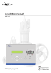
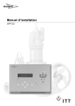
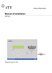
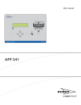
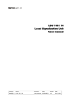
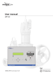
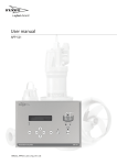
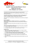
Installation manual
Esc
Autamatic Pump Pilot
APP 541
OK
Reset
APP 541
Table of Contents
Table of Contents
Read this first...........................................................................................................................................2
Introduction..........................................................................................................................................2
Product Overview................................................................................................................................2
Safety rules for the owner/operator.................................................................................................. 2
Guarantee.............................................................................................................................................2
This manual.......................................................................................................................................... 2
Safety Instruction................................................................................................................................. 3
Mechanical installation.......................................................................................................................... 4
Installing the Unit.................................................................................................................................4
Level sensor installation......................................................................................................................5
Electrical installation.............................................................................................................................. 7
Safety instruction................................................................................................................................. 7
Power supply........................................................................................................................................7
Emergency operation......................................................................................................................... 8
Connections......................................................................................................................................... 8
Communication................................................................................................................................... 9
Wiring diagram.................................................................................................................................... 11
Wiring diagram 100-240 V AC........................................................................................................ 11
Wiring diagram 24 V DC.................................................................................................................. 12
Troubleshooting...................................................................................................................................14
Troubleshooting................................................................................................................................14
Technical Specification........................................................................................................................15
Technical specification..................................................................................................................... 15
Options and Accessories................................................................................................................. 18
APP 541 Installation manual
1
Read this first
Read this first
Introduction
Before starting installation of the APP 541 read this chapter carefully. It contains general
information on documentation, safety and guarantee.
This manual is applicable to the following APP 541 versions:
Hardware:
• Operator panel: AFH1801 Rev 1.02 or later
• I/O-module: AHH1801 Rev 1.02 or later
• Com-module: TMX1801 Rev 1.00 or later
System Software: 2.73 or later
Application: 1.44 or later
Product Overview
APP 541 is a pump controller. It consists of two parts: a DIN rail-mounted I/O-module, and
an operator panel.
APP 541 can use a PSTN, GSM, GPRS or radio modem to communicate with a SCADA
system, for example AquaView. A special communication module is available for this
purpose.
Safety rules for the owner/operator
• All government regulations, local health and safety directives must be observed.
• All danger due to electricity must be avoided.
Guarantee
• Modifications or changes to the unit/installation should be done only after consulting
Xylem.
• Genuine spare parts and accessories authorized by the manufacturer are essential for
compliance with the terms of the guarantee. The use of other parts may invalidate the
guarantee.
This manual
In order to avoid repetition of information, this manual describes how one pump P1,
should be read or entered. If a second pump or more pumps, are included in the
installation, the corresponding steps must be repeated on those too.
Symbols used
WARNING:
Safety instruction
Risk of personal damage.
Electrical Hazard:
Safety instruction
Risk of personal damage - dangerous voltage.
2
APP 541 Installation manual
Read this first
NOTICE:
Special attention value
Risk of apparatus or component damage.
Safety Instruction
NOTICE:
Observe all precautions for handling electrostatically sensitive devices before opening the
unit.
The front surface of the APP 541 has a high degree of protection against moisture and dirt,
but should always be installed so that it will not be unnecessarily exposed to water or the
risk of external physical damage.
The APP 541 may be used only in the manner specified by the manufacturer.
The manufacturer does not allow any internal modifications to be made in the unit.
Always keep this manual in the vicinity of the installed unit.
APP 541 Installation manual
3
Mechanical installation
Mechanical installation
Installing the Unit
WARNING:
• The unit must never be installed in an explosive or flammable environment.
• If the pump is installed in an explosive environment, its thermal overload switch must be
connected
Equipment cubicle
Ensure that the operating temperature of the cubicle is between -4° F and +122° F.
Heating will normally be required in winter if the cubicle is located outdoors or in a
similarly cold environment.
The cubicle temperature may become too high in summer if ventilation is inadequate.
Heating of the cubicle is also recommended to avoid condensation.
Mounting instructions
The enclosure is designed for mounting into a rectangular hole in a larger cabinet door.
A rubber gasket will seal against the front surface of the cabinet door. Studs welded to the
rear of the front plate must enter into holes in the cabinet door.
1. Mark the positions of holes A and B on the cubicle door.
7.87 in
7.24 in
A
0.31 in
A
B
B
B
A
0.31 in
5.31 in
4.69 in
B
A
Figure 1
2. Drill small pilot holes, and then open up:
• Holes marked A to 3/16 in (5 mm) in diameter.
• Holes marked B to 5/16 in (8 mm) in diameter.
4
APP 541 Installation manual
Mechanical installation
3. Tape with masking tape between the outsides of holes marked B.
B
B
B
B
Figure 2
4. Use a jigsaw or some other suitable tool to make the opening for the operator panel
in the cubicle door.
5. Place the operator panel in the opening. Fit the washers and nuts, and tighten them
firmly.
Notice about mounting front seal according to IP 65
WARNING:
Be careful not to get any grease in your eyes and avoid prolonged skin contact. Wash your
hands afterwards.
To assure a front seal according to IP 65 the front unit has to be mounted on to a rigid and
smooth surface.
If otherwise mounted on to a textured surface and/or flexible steel plate cabinet, it is
normally necessary to apply a thick layer of grease on the sealing surfaces to obtain sealing
according to IP 65.
Suitable grease is "Gleitmo 1810v". After application wipe gently all overflowing grease
away.
NOTICE:
Do never use grease containing silicone since this might seriously damage sensitive
electric contact surfaces inside the cabinet!
I/O-module
The I/O-module has clamps at the rear.
1. Place the unit in a suitable location on a DIN rail.
2. Connect the cables supplied between the operator panel and the I/O-module.
Secure the cable so that they will not be nipped.
Note: The Ethernet cable is a crossover UTP RJ 45 cat 5e. The cable length is 6 ft (max
length 10 ft).
Level sensor installation
N.B. For details on installation in the pump sump, refer to the level sensor documentation.
APP 541 Installation manual
5
Mechanical installation
4-20 mA level sensor
WARNING:
The sensor may be installed in an explosive or flammable environment, provided that an
external Ex barrier is used.
The sensor shield must be connected to the earth (ground) terminal of the APP 541 as
shown in the diagram under Connections (page 8).
ENM-10 level regulator
WARNING:
ENM-10 level regulators may be installed in an explosive or flammable environment,
provided that an intrinsically safe Ex barrier is used.
The figure shows installation of ENM-10 level regulators in the pump sump.
High level switch
Low level switch
Figure 3
6
APP 541 Installation manual
Electrical installation
Electrical installation
Safety instruction
Electrical Hazard:
Do not open machine with the grounding wire disconnected.
More than one live circuit.
The electric wiring should be done only by an authorized electrician. All electrical
installation work must be carried out with the equipment disconnected from the power
supply, without any possibility of being made live, and in accordance with local
regulations.
An ON / OFF isolating switch must be provided adjacent to the installation to enable the
APP 541 to be isolated from the power supply. This isolating switch must be located close
to the APP 541 and must be easily accessible to the user.
The isolating switch should be marked to show that it belongs to the APP 541.
When installing electronic measuring and control systems, it is important that the cabling
be specified and run so as to minimize interference by electric and magnetic fields.
The many potential sources of such interference include relay coils, solenoid valves,
switches, thyristor units, earth (ground) currents and static electrical discharges.
Susceptibility to interference also varies with the electrical environment, i.e. due to factors
such as cable lengths, screening and whether or not interference suppression is provided.
Many problems can be prevented by good design.
Cables carrying signals of different types (for example, analogue and digital signals) must
be run separately. Power and signal cables must never be run in close proximity to one
another.
Power supply
A separate fuse must protect the APP 541 power supply. Xylem recommends the use of a
miniature circuit breaker that opens on all poles.
• One I/O module is designed to operate on 100 to 240 V AC power supply. The unit
can also operate on 24 V DC as backup power supply and can charge the backup
battery when the mains power supply is on.
• One model designed to operate at 24 v DC.
The I/O module also supplies power to the operator panel.
N:B. Max. current available to the modem:
24 VDC, 180 mA, 4.5 Watt
Earthing (grounding)
An equipment earthing (grounding) conductor must be connected to terminal 3 (see
Wiring diagram).
The earthing conductor should be connected to the best possible earth, such as an
earthed mounting plate or an earth rod. Remember that the earthing conductor must be as
short as possible.
The shields of all shielded cables must be earthed.
Overvoltage protection
Xylem recommends that the mains power supply unit be provided with overvoltage
protection (with lightning protection). Since this will make the APP 541 less sensitive to
overvoltage, it will enable it to be used in more severe environments.
APP 541 Installation manual
7
Electrical installation
The protection should be connected in series with the power supply, preferably to a
separate earth (ground), such as an earth rod, although connection to the earth busbar in
the distribution box may sometimes suffice.
A 10–7 AWG earthing wire should be used to connect the overvoltage protection to earth.
Emergency operation
When the control unit is in the normal running mode a relay will be activated. If the control
unit should fail, due to software, hardware or power supply fault, the relay will be
deactivated.
This relay can be connected between a high level switch, a timer and a power supply relay
controlling the pump. This function will provide an emergency function that will run the
station on the high-level switch even if the control unit is out of operation.
Connections
The terminal blocks on the APP 541 are described below and are shown in the Wiring
diagram 100-240 V AC (page 11).
Digital inputs
The digital inputs are connected to terminals 28 -59 (see the Wiring diagram 100-240 V AC
(page 11)). Each input has power supply, but the (+) terminals for all inputs are
connected internally.
Inversion of inputs
The digital input signals can be inverted to change the operating mode from closing to
opening, or vice versa.
0 indicates no inversion. This is the default state.
See the User manual.
Analogue input
Analogue terminals
Table 1
3
Shield
4
+ (24 VDC)
5
(input)
6
- (0 V)
7-8
Input for current transformer with 0-1 A AC output
9-10
Input for current transformer with 0-1 A AC output
Passive sensor
8
APP 541 Installation manual
Electrical installation
A passive sensor (4-20 mA) is connected to terminals 4–5 (see the Wiring diagram (page
11)) and is powered by the MIO 501 board. The input can carry a maximum total voltage
of 16 V.
L
N
1
2
4 5 6 7 8 9 10
3
+
-
Figure 4
Active sensor
An active sensor (4-20 mA) has its own power supply and is connected to terminals 5–6
(see the Wiring diagram (page 11)).
L
N
1
2
3
4 5 6 7 8 9 10
+
-
24
VDC
Figure 5
Digital outputs
The digital outputs are connected to terminals 11-22 (see the Wiring diagram (page 11)).
The outputs are potential-free, relays with a max. rating of 2 A at 230 V AC or 30 V DC.
Communication
To install the communication module in the operator panel, follow the instructions below:
N:B: Make sure that the power supply is disconnected!
APP 541 Installation manual
9
Electrical installation
1. Release the four screws (1) holding the rear cover to the front of the unit.
2. Lift off the rear cover (2).
1
2
Figure 6
3. Unpack the communication module (3).
4. Place module (3) in the position (4).
3
4
Figure 7
5. Make sure it is securely in position.
6. Refit the rear cover.
Connection to communication equipment
Connect the enclosed dedicated modem cable from the modem/radio to the RS232
connector on the COM1.
Connect the modem/radio to a power supply.
Connection to a PC using a fixed line
Connect a dedicated null-modem cable from the PC to the RS232 connector on the
COM1.
N.B. A common misunderstanding is to confuse the use of a modem cable and a nullmodem cable. Normally a modem cable has a male contact in one end and female contact
in the opposite end. The null-modem cable has normally female contacts in both ends.
Note that they are different connected internally to the contact pins. Be sure to use the
right cable for each purpose.
N.B. For configuration, see the User manual.
10
APP 541 Installation manual
Wiring diagram
Wiring diagram
Wiring diagram 100-240 V AC
Table 2
A
Power supply (See also Power supply
(page 7)):
Power supply (See also Power supply
(page 7)):
Power supply, phase, neutral and
M
ground: 100-240V AC, 50/60 Hz. (1, 2,
3)
Battery backup 24 V DC (Option) (26,
27)
Analogue inputs (See also Connections
(page 8)):
Digital inputs (See also Connections
(page 8)):
B
Level sensor input, 4-20 mA. (4, 5, 6)
N
Motor protector to pump 1. (28, 29).
C
Current transformer for pump 1/3, 0-1
A AC (7, 8)
O
Start-feedback from pump 1. (30, 31)
D
Current transformer for pump 2/4, 0-1
A AC (9, 10)
P
Motor protector to pump 2. (32, 33)
Digital outputs (See also Connections
(page 8)):
Q
Start feedback from pump 2. (34, 35)
E
Start pump 1 (11, 12)
R
Motor protector to pump 3. (36, 37)
F
Start pump 2 (13, 14)
S
Start feedback from pump 3. (38, 39)
G
Start pump 3 (15, 16)
T
Motor protector to pump 4. (40, 41)
H
Start pump 4 (17, 18)
U
Start feedback from pump 4. (42, 43)
I
Common alarm output (19, 20)
V
General purpose input 1. (44, 45)
J
Emergency operation (21, 22)
X
General purpose input 2. (46, 47)
Operator panel (See also Installing the
Unit (page 4)):
Y
General purpose input 3. (48, 49)
K
Operator panel 24 V DC (23, 24)
Z
General purpose input 4. (50, 51)
L
Communication to operator panel (25)
AA
General purpose input 5. (52, 53)
AB
General purpose input 6. (54, 55)
AC
General purpose input 7. (56, 57)
AD
General purpose input 8. (58, 59)
APP 541 Installation manual
11
Wiring diagram
N
M
O
R
Q
P
T
U
X
V
36 37 38 39 40 41 42 43
28 29 30 31 32 33 34 35
Y
AB
AA
Z
44 45 46 47 48 49 50 51
AC
AD
52 53 54 55 56 57 58 59
or
B
ba atte
ck ry
up
pr
ot
ec
to
St
rP
ar
1
tf
ee
db
M
ot
ac
or
k
P1
pr
ot
ec
to
St
rP
ar
2
tf
ee
db
ac
k
P2
M
ot
or
pr
ot
ec
to
St
rP
ar
tf
3
ee
db
M
ac
ot
or
k
P3
pr
ot
ec
to
St
rP
ar
tf
4
ee
db
ac
G
k
en
P4
er
al
pu
rp
G
os
en
e
er
in
al
pu
pu
t1
G
rp
en
os
er
e
al
in
pu
pu
t2
rp
G
en
os
er
e
in
al
pu
pu
t3
rp
os
e
in
G
pu
en
t4
er
al
pu
G
rp
en
os
er
e
al
in
pu
pu
t5
rp
G
en
os
e
er
in
al
pu
pu
t6
rp
os
e
in
pu
t7
26 27
S
l
M
ot
a
er
8
ut
e
os
p
in
rp
pu
en
G
APP 541
A
B
7
8
C
9
10
D
11
12
E
21
H
I
22
O
24
ar
ge
on
er
m
om
ar
19 20
St
18
nc
y
al
p
um
um
tp
tp
ar
St
G
17
at
io
n
V
D
pe C
ra to
to
rp
an
To
el
O
pa pe
ne ra
l tor
t
er
ou
F
15 16
op
m
13 14
4
3
p
2
p
um
tp
ar
6
Em
4
C
3
St
5
C
2
Le
ly
AC
/2
30
V
pp
Su
er
Po
w
11
5
1
Si
ve
lS
gn ens
o
al
ur
G r in
N
r
e
D p 40- n
1A t T
20
r
m
C AC ans
A
ur
fo
r
rm
0- ent
er
1A T
P1
AC ran
/
P3
sf
or
m
er
St
P2
ar
/P
tp
4
um
p
1
MIO 501
APP 541
23 24
J
K
25
L
Figure 8
N.B. Terminals 6, 8 and 10 are connected together internally.
N.B. Terminals 29, 31, 33.......59 are connected together internally.
N.B. I and J are activated at normal operation.
Wiring diagram 24 V DC
Table 3
A
Analogue inputs(See also Connections
(page 8)):
M
Power supply 24 V DC input or Battery
backup 24 V DC (Option) (26, 27)
Digital inputs (See also Connections
(page 8)):
B
Level sensor input, 4-20 mA. (4, 5, 6)
C
Current transformer for pump 1/3, 0-1
A AC (7, 8)
N
Motor protector to pump 1. (28, 29)
D
Current transformer for pump 2/4, 0-1
A AC (9, 10)
O
Start-feedback from pump 1 (30, 31)
Digital outputs (See also Connections
(page 8)):
P
Motor protector to pump 2. (32, 33)
E
Start pump 1 (11, 12)
Q
Start feedback from pump 2. (34, 35)
F
Start pump 2 (13, 14)
R
Motor protector to pump 3. (36, 37).
G
Start pump 3 (15, 16)
S
Start feedback from pump 3. (38, 39)
H
Start pump 4(17, 18)
T
Motor protector to pump 4 (40, 41)
I
Common alarm output (19, 20)
U
Start feedback from pump 4. (42, 43)
J
Emergency operation (21, 22)
V
General purpose input 1. (44, 45)
Operator panel (See also Installing the
Unit (page 4)):
X
General purpose input 2. (46, 47)
Operator panel 24 V DC (23, 24)
Y
General purpose input 3. (48, 49)
K
12
Power supply (See also Power supply
(page 7)):
Ground (3)
APP 541 Installation manual
Wiring diagram
Communication to operator panel (25)
N
M
T
U
Y
44 45 46 47 48 49 50 51
AA
General purpose input 5. (52, 53)
AB
General purpose input 6. (54, 55)
AC
General purpose input 7. (56, 57)
AD
General purpose input 8. (58, 59)
AB
AA
Z
General purpose input 4. (50, 51)
AC
ot
St
pr
or
ot
M
AD
52 53 54 55 56 57 58 59
rP
ar
tf
3
ee
db
ac
ot
or
k
P3
pr
ot
ec
to
St
rP
ar
tf
4
ee
db
ac
G
k
en
P4
er
al
pu
rp
G
os
en
e
er
in
al
pu
pu
t1
G
rp
en
os
er
e
al
in
pu
pu
t2
rp
G
en
os
er
e
in
al
pu
pu
t3
rp
os
e
in
G
pu
en
t4
er
al
pu
G
rp
en
os
er
e
al
in
pu
pu
t5
rp
G
en
os
e
er
in
al
pu
pu
t6
rp
os
e
in
pu
t7
P2
k
ac
X
V
36 37 38 39 40 41 42 43
db
ct
te
ee
pr
o
tf
ar
St
S
Z
ec
to
P1
P2
or
ck
or
ot
M
St
a
rt
fe
te
ed
ct
ba
or
w
er
D
C
Po
V
pr
o
M
ot
or
24
R
Q
P
28 29 30 31 32 33 34 35
P1
26 27
O
M
L
en
al
er
r
pu
pu
se
t8
in
po
G
APP 541
A
B
7
8
C
9
10
D
11
12
E
H
ar
al
on
m
19 20
21
I
er
at
io
24
n
V
O DC
pe
ra to
to
rp
an
To
el
O
pa pe
ne ra
l tor
ou
t
18
om
ar
St
17
ge
nc
y
p
um
um
G
tp
tp
ar
15 16
op
m
F
4
3
p
2
p
13 14
St
um
tp
ar
6
St
5
Em
er
4
C
3
Si
2
1
Le
ve
l
Se
gn ns
o
al
C
ur
G r in
N
D p 40- ren
1A t T
20
r
m
C AC ans
A
ur
fo
r
rm
0- ent
er
1A T
P1
AC ran
/
P3
sf
or
m
er
St
P2
ar
/P
tp
4
um
p
1
MIO 501
APP 541
22
J
23 24
K
25
L
Figure 9
N.B. Terminals 6, 8 and 10 are connected together internally.
N.B. Terminals 29, 31, 33.......59 are connected together internally.
N.B. I and J are activated at normal operation.
APP 541 Installation manual
13
Troubleshooting
Troubleshooting
Troubleshooting
Power on LED does not
light up.
Alarm status LED red.
Is power supply off?
No
Alarm status LED
Red
Yes Check the external
mains switch and
mains fuse or
miniature circuit
breaker.
Check Alarm log menu
Alarm:
High temperature,
P1 - P4
Contact FLYGT service
agent
No
Yes
Yes
Thermal overload switch in
motor winding has
tripped due to
high temperature.
No
Pump fails to start
No
Contact FLYGT service
agent
Yes
Check that Manual
0-Auto selector is
set to Auto.
If not Manual-0Auto is used,
jumper the auto
input.
Alarm:
Tripped, P1 - P4
Check that Auto is
selected in from P1
Status to P4 Status
menu as
appropriate. Alter if
necessary
External motor
protection has tripped
Check configuration of
general purpose inputs and
wiring for thermal
overload switch
Pump is damaged (e.g.
bearing failure, winding
fault); pump impeller is
jammed
Contact FLYGT service
agent
Blocked, displays steady
light (Pump status
indicator, red LED)
Go to next Alarm.
No
Go to next Alarm.
Yes
Yes
No
Contact FLYGT service
agent
Alarm:
Max run, P1 - P4
No
Contact FLYGT service
agent
Yes
Check external motor
protector .
Pump is running on
two phases
Pump is damaged
(e.g. bearing failure,
winding fault); pump
impeller is jammed
Check start and stoplevels from Start level 1,
Stop level 1 to Start level
4 and Stop level 4 menus
as appropriate.
Check time setting in Max
run time menu and adjust
if necessary.
Pump impeller is
damaged and delivering
insufficient flow.
Level sensor is faulty.
High-level switch or start/
stop switch is faulty.
Figure 10
14
APP 541 Installation manual
Technical Specification
Technical Specification
Technical specification
Approved Standards
EMC emission Standard
EN61000-6-3
EMC immunity standard
EN61000-6-2
LVD electrical safety
EN61010-1
CSA
C22.2 No. 14-95
UL
UL 61010-1
Power Supply
AC version
Rated Voltage
100-240 V AC 50-60 Hz
Rated Power
25 W
Current Consumption
< 200 mA at 230 V AC
Fuse
3,15 A
DC version
Rated Voltage
24 V DC (18-36 V DC)
Rated Power
20 W
Current Consumption
<1 A at 24 V DC
Fuse
1,1 A
Operational temperature
-4º F to +122º F1
Storage Temperature
+14º F to +158º F
Humidity (non-condensing)
90% RH
Enclosure, Operator panel, front side:
IP 65
Enclosure, I/O unit, Operator panel, back side:
IP 20
Environment
1
LCD display will respond more slowly at temperatures below 32° F.
Material
I/O Unit
Weight
2.0 lb
Enclosure
Aluminum
Side gable
Painted steel
Upper side
Polycarbonate
Mounting
Cabinet
Dimensions (LxWxH)
8.27 x 5.87 x 1.85 in
APP 541 Installation manual
15
Technical Specification
Operator Panel
Weight
2.2 lb
Enclosure
Galvanized steel
Gasket
EPDM
Overlay
Polyester
Mounting
Cabinet
Dimensions (LxWxH)
8.66 x 5.91 x 0.98 in
Data Processing Power
Processor
Freescale HCS12
Executed word length
16 bits
Clock frequency
29,5 MHz
Application Memory (Flash)
256 kB
System Memory (Flash)
256 kB
Parameter Memory (EEPROM)
8 kB
Battery backup
Yes, Real-time clock
Watchdog
Yes
Display
LCD 2x20 character
Push buttons
8 pcs
LED indications
12 pcs
User Interface
Digital Inputs
Note! APP 541 only supports analog level sensor, and not digital start and stop level
switches.
16
APP 541 Installation manual
Technical Specification
Motor protector (thermal) 3:
• Pump 1, Pump 2, Pump 3, Pump 4
Start relay feedback:
• Pump 1, Pump 2, Pump 3, Pump 4
General input 1, 2, 3 and 4: 4
• Blocking of pumps
• External alarm
• High level switch
• Low level switch
• Manual mode pump 1 (input 1 only) 5
• Manual mode pump 2 (input 2 only) 5
• Manual mode pump 3 (input 3 only) 5
• Manual mode pump 4 (input 4 only) 5
• Overflow sensor
• Personnel alarm
• Power failure
• Pump 1 fault (thermal, leakage) 3
• Pump 2 fault (thermal, leakage) 3
• Pump 3 fault (thermal, leakage) 3
• Pump 4 fault (thermal, leakage) 3
• Rain meter 2
General input 5, 6, 7 and 8: 4
• Auto mode pump 1 (input 5 only)
• Auto mode pump 2 (input 6 only)
• Auto mode pump 3 (input 7 only)
• Auto mode pump 4 (input 8 only)
• Blocking of pumps
• External alarm
• High level switch
• Low level switch
• Overflow sensor
• Personnel alarm
• Power failure
• Rain meter 2
2 Counter input.
3 Input when using thermal contact or supervision relay.
4 Monitoring up to eight external circuits, the general inputs can be assigned in all
combinations that make logical sense.
5 Mandatory in ATEX mode.
Analogue Inputs
Level sensor input
Analogue level
4-20 mA
Inaccuracy
0,5% FS
Resolution
10 bits
APP 541 Installation manual
17
Technical Specification
Current transformer inputs
Analogue current CT6 0-1 A AC
Pump 1 and 3, Pump 2 and 4 7
Inaccuracy
2% FS
Resolution
10 bits
6 CT=external
7 Pump
current transformer with 0-1 A on secondary side.
currents are measured in pairs.
Digital Outputs
Start pump
Pump 1, Pump 2, Pump 3, Pump 4
Common alarm
Emergency operation
Rated load
2 A by 240 V AC or 30 V DC
Type of Sensors to be Used
• 4-20 mA level sensor
• ENM-10 level regulator
Terminals
Signal
16 AWG
Power
13 AWG
Connects
I/O unit and operator panel
Cable type
Crossover UTP RJ 45 cat 5e
Cable length
6 ft (max length 10 ft)
Ethernet Cable
Communication
Protocol:
• AquaCom
• Comli
• Modbus
• SMS text
Approved Modems
Contact your local Xylem supplier for valid modems in your area.
Options and Accessories
Table 4: Power supply and Battery backup unit
18
Part No
Description
40 501483
Power supply with batteries 2.2Ah
40 501517
Power supply with batteries 7.2Ah
40 501216
Power supply DR-75-24 => 230 or 115VAC/24 VDC 3.2A
APP 541 Installation manual
Technical Specification
Part No
Description
40 501190
APP battery backup unit (2Ah) to be used with (40 501216)
Table 5: Level sensor 4-20 mA (pressure transmitter)
Part No
Description
40 501200
LTU501, Range 0-5,0 m, 15 m cable
40 501201
LTU501, Range 0-10,0 m, 15 m cable
40 501202
LTU501, Range 0-2,0 m, 10 m cable
40 501203
LTU501, Range 0-5,0 m, 10 m cable
40 501204
LTU501, Range 0-5,0 m, 20 m cable
40 501205
LTU501, Range 0-5,0 m, 30 m cable
40 501206
LTU501, Range 0-10,0 m, 10 m cable
40 501207
LTU501, Range 0-10,0 m, 20 m cable
40 501208
LTU501, Range 0-10,0 m, 30 m cable
843061
LS100, Range 0-3,5 m, 20 m cable
843058
LS100, Range 0-5,0 m, 15 m cable
843062
LS100, Range 0-5,0 m, 25 m cable
843059
LS100, Range 0-10 m, 15 m cable
Table 6: Ultrasonic level sensors 4-20mA
Part No
Description
839422
LSU100, Range 0-5 m, 15 m cable
839424
LSU100, Range 0-10 m, 10 m cable
Table 7: Overflow sensor
Part No
Description
843053
S003, Overflow sensor, 15 m cable
843054
S003, Overflow sensor, 25 m cable
Table 8: Level regulator (Can only be used for High/Low level)
APP 541 Installation manual
Part No
Description
582 88 02
ENM-10 Blue, 1,2 kg / 0,95-1,10 / 6m
582 88 03
ENM-10 Blue, 1,7 kg / 0,95-1,10 / 13m
19
Technical Specification
Part No
Description
582 88 04
ENM-10 Blue, 2,2 kg / 0,95-1,10 / 20m
Table 9: Over voltage protection (Zener barrier)
Part No
Description
843052
Single channel safety barrier for transmitters 4-20 mA (Active)
840107
Two channel safety barrier for ENM-10 (Digital Switch)
Table 10: Current transformer
Part No
Description
40 501210
Current transformer 50/1A
40 501481
Current transformer 100/1A
Table 11: Communication equipment
20
Part No
Description
40 501152
Communication module including modem cable
40 501529
Modem, TDW-33 12-36 VDC, (V90) Europe
40 501530
Modem, TDW-33 12-36 VDC, (V23), Europe
40 501300
Modem, GDW-11 GSM modem, 24 VDC
40 501465
Modem, EDW-100 serial ethernet adapter, 24 VDC
40 501275
Antenna, Low-Profile Roof Mounted GSM antenna
40 500956
Power supply, PS-12 12 V 10W for TDW-33, GDW-11, EDW-100
Installation
date
........................................................................................................................................................
Name
........................................................................................................................................................
APP 541 Installation manual
Xylem |’zīləm|
1) The tissue in plants that brings water upward from the roots
2) A leading global water technology company
We're 12,000 people unified in a common purpose: creating
innovative solutions to meet our world's water needs. Developing new
technologies that will improve the way water is used, conserved, and
re-used in the future is central to our work. We move, treat, analyze,
and return water to the environment, and we help people use water
efficiently, in their homes, buildings, factories and farms. In more than
150 countries, we have strong, long-standing relationships with
customers who know us for our powerful combination of leading
product brands and applications expertise, backed by a legacy of
innovation.
For more information on how Xylem can help you, go to xyleminc.com
Xylem Water Solutions AB
Gesällvägen 33
174 87 Sundbyberg
Sweden
Tel. +46-8-475 60 00
Fax +46-8-475 69 00
http://tpi.xyleminc.com
Visit our Web site for the latest version of this document and
more information
The original instruction is in English. All non-English
instructions are translations of the original instruction.
©
2011 Xylem Inc
896810_2.2_en.US_2012-10_IOM_ APP541