1
Sarasota 200
Ultrasonic Multipath Flowmeter
User Guide
P/N HB-S200
Revision A
Part of Thermo Fisher Scientific
Sarasota 200
Ultrasonic Multipath Flowmeter
User Guide
P/N HB-S200
Revision A
©2007 Thermo Fisher Scientific Inc. All rights reserved.
All trademarks are the property of Thermo Fisher Scientific Inc. and its subsidiaries.
Thermo Fisher Scientific (Thermo Fisher) makes every effort to ensure the accuracy and completeness of
this manual. However, we cannot be responsible for errors, omissions, or any loss of data as the result of
errors or omissions. Thermo Fisher reserves the right to make changes to the manual or improvements to
the product at any time without notice.
The material in this manual is proprietary and cannot be reproduced in any form without expressed
written consent from Thermo Fisher.
Thermo Fisher Scientific
1410 Gillingham Lane
Sugar Land, TX 77478
USA
Phone: 713-272-0404
Fax: 713-272-2272
Web: www.thermofisher.com
Thermo Fisher Scientific
14 Gormley Industrial Avenue
Gormley, Ontario L0H 1G0
Canada
Phone: 905-888-8808
Fax: 905-888-8828
This page intentionally left blank.
Sarasota 200 Ultrasonic Multipath Flowmeter
INDEX
SECTION 1
INTRODUCTION
1.1 Applications
1.2 Principle of operation
1.2.1 The Standard
1.2.2 Velocity x area method
1.2.3 Water level
1.2.4 Water velocity
1.2.5 Flow determination
1.2.5.1 Mid section method
1.2.5.2 Mean section method
1.2.6 Path configurations
1.2.7 Transducer frequency
1.2.8 Minimum depth of water
1.2.9 Performance estimates
1.3 Implementation of principles in Sarasota 200
SECTION 2
SYSTEM COMPONENTS
2.1 Flowmeter system overview
2.2 Family tree
2.3 Flowmeter contents and options
2.3.1
Flowmeter layout
2.3.2
Internal components
2.3.2.1 Mother board
2.3.2.1.1 Power supply & internal battery
2.3.2.1.2 Transducer connections
2.3.2.1.3 Depth input signals
2.3.2.1.4 Output signal connections
2.3.2.1.5 Relay connections
2.3.2.1.6 Digital signal connections
2.3.2.1.7 Serial communications
2.3.2.2 Central processor (CPU)
2.3.2.3 LCD display
2.3.2.4 Transducer interface card (TIF)
2.3.2.5 AC power adapter
2.4 Ultrasonic transducers
2.4.1
1 MHz transducers
2.4.2
1 MHz I.S. transducers
2.4.3 500 kHz transducers
2.4.4 Lower frequency transducers
2.4.5 Maximum cable lengths
2.5 Controls and displays
2.6 Software & firmware
2.6.1 Operating firmware
2.6.2 “GAFA” PC software
2.7 Documentation
INDEX Page 1
Thermo Fisher Scientific
Sarasota 200 Ultrasonic Multipath Flowmeter
INDEX
SECTION 3
PERIPHERAL EQUIPMENT
3.1 Additional items
3.2 Transducer mounting hardware
SECTION 4
INSTALLATION
4.1 Safety
4.2 General
4.3 Unpacking and laying out
4.4 Installing transducer assemblies
4.5 Connecting transducers to flowmeter
4.6 Transducer alignment
4.7 Output connections
4.8 Power connection
SECTION 5
COMMISSIONING
5.1
5.2
5.3
5.4
5.5
Site dimensions
Powering up
Programming
Setting up
Outputs
SECTION 6
CALIBRATION/
VERIFICATION
6 Calibration/verification
SECTION 7
MAINTENANCE
7.1 Channel maintenance
7.1.1 Weed
7.1.2 Profile
7.1.3 Debris
7.2 Flowmeter maintenance
7.3 Routine checks
7.3.1
7.3.2
Remote
On site
APPENDIX 1
GAFA PC SOFTWARE
A2 GAFA PC software
INDEX Page 2
Thermo Fisher Scientific
Sarasota 200 Ultrasonic Multipath Flowmeter
INDEX
APPENDIX 2
SPECIFICATION
A2.1 Enclosure
A2.2 Power supply
A2.2.1 DC supply
A2.2.2 AC power adapter module
A2.3.3 Internal battery option
A2.3 Electronics
A2.4 Transducers
A2.4.1 1 MHz
A2.4.2 500 kHz
A2.4.3 Other frequencies
A2.4.4 Transducer cable
A2.5 GAFA software
APPENDIX 3
REFERENCES
A3 References
APPENDIX 4
SITE DATA BOOK
A4.1
A4.2
A4.3
A4.4
A4.5
A4.6
A4.7
A4.8
APPENDIX 5
I.S. INTERFACE AND
TRANSDUCER
INDEX Page 3
Model and serial number
Site and customer
General description
Software issue
Card layout in rack
Programmed data
Schedule of drawings
Test certificates
A5.1 Introduction
A5.2 Installation Guidelines
A5.3 Marking
A5.4 Maintenance
Thermo Fisher Scientific
Sarasota 200 Ultrasonic Multipath Flowmeter
INDEX
This page is blank
INDEX Page 4
Thermo Fisher Scientific
Sarasota 200 Ultrasonic Multipath
Flowmeter
1
INTRODUCTION
1.1
Applications
INTRODUCTION
The Thermo Scientific Sarasota 200 is a velocity x area open channel flowmeter which uses
the ultrasonic “time of flight”, also known as the “transit time” method. It is similar to the larger
Sarasota 2000 but with fewer ultrasonic velocity paths (up to 4) and just one water channel.
Unlike traditional methods of open channel flow measurement which use weirs or flumes, the
transit time method creates no obstruction and assumes no relation between level and flow. It
will correctly determine flow throughout its designed range by measuring water velocity and
cross section area (see Section 1.2).
The method is tolerant of backwater effects caused by tides, downstream confluence or
blockages. Unlike a weir or flume it does not drown out at high flow conditions.
The method employs the transmission of ultrasonic “beams” which can be affected by factors
which impede or deflect them. For this reason the method should not be used in situations of:
•
•
•
•
•
Aerated water
Weed growth between the transducers (unless it is regularly cut)
High levels of suspended solids (greater than 2000 mg/l) *
Gradients of salinity (the actual value of salinity is, however, unimportant**)
Gradients of temperature (the actual temperature is, however, unimportant**)
*
In relatively small channels (up to 5 metres) the method is more tolerant of
suspended solids and therefore is often used in sewage applications.
**
Provided the velocity of sound in water (VOS) remains within the range 1350 to 1650
m/s
Though described as an open channel method, the flowmeter may be used in closed
conduits, including those which run full. In the latter case, the cross section area is defined by
the conduit geometry without the need to measure water level.
Suitable applications include water flow measurement of:
•
•
•
•
•
•
•
•
Rivers
Canals
Aqueducts
Irrigation conduits
Sewage discharges
Sewage works
Industrial discharges
Power generation
Note that although the flowmeter is most often used for open channels or part filled conduits,
it is often used for conduits which always run full. Under these circumstances it is not
necessary to have a depth input but steps need to be taken to ensure that the flowmeter
always takes the conduit as full. This is done via the fixed level input PC screen. The conduit
shape must still be entered.
Section 1 INTRODUCTION Page 1-1
Thermo Fisher Scientific
Sarasota 200 Ultrasonic Multipath
Flowmeter
1.2
INTRODUCTION
Principle of operation
1.2.1 The Standard
The Thermo Scientific Sarasota 200 is an ultrasonic “transit time” flowmeter which complies
with the International Standard ISO 6416. The UK standard BS 3680 part 3E is identical. The
transit time method belongs to the general category of velocity x area methods. A full
description of the method and its applications is to be found in the Standard. A brief summary
is given below.
1.2.2 Velocity x area method
Velocity x area methods require a means of determining the water velocity and the cross
section area. The product of the two determines the flow rate in a manner which is not
dependent on factors influencing the level, for example downstream constrictions, tidally
affected water level etc.
Assuming the shape of the channel cross section is stable, determination of the area
becomes a matter of measuring water level. This may be done by a variety of methods.
1.2.3 Water level
Water level is required in order to determine the cross section area in an open channel.
Though a single level measurement may be used, it is common to use more than one and to
average them. This has the advantage of a more representative level, particularly if the
measurements are made at different positions, for example on either side of the channel.
Another advantage is that flow may still be computed even if a level sensor fails.
Level may be determined by using one or more ultrasonic transducers in the water facing
upwards. The time taken for a pulse of sound to return to the transducer after being reflected
from the surface is converted into level using the velocity of sound in water as measured by
the water velocity paths (see Section 1.2.4). There is a minimum depth of water required
above the transducer for it to carry out a measurement. This is given in Appendix 2:
Specification.
Water level may also be provided by external auxiliary depth gauges via 4-20 mA signals, for
example pressure transmitters, downward facing ultrasonic devices and float systems with
shaft encoders.
1.2.4 Water velocity
In the transit time method, water velocity is determined at a number of heights within the body
of water by measurement of time taken for pulses of ultrasound to travel across the channel
at an angle to the flow direction.
Transducers are mounted in the water at or near the sides of the channel with each pair
usually at the same height and aligned so that each one can transmit a “beam” of ultrasound
towards its partner. The ultrasonic “path” between the transducer pairs must be at an angle
(usually about 45o) to the flow direction.
Each transducer acts as a transmitter and receiver and is connected to a processing unit,
which measures the transit time and the time difference.
Section 1 INTRODUCTION Page 1-2
Thermo Fisher Scientific
Sarasota 200 Ultrasonic Multipath
Flowmeter
INTRODUCTION
The mean water velocity at the height of each path is determined from these timing
measurements, based on pre-determined geometrical measurements (length of the path and
the angle to the flow direction).
Transducer A
θ
V
Direction of the Flow
Ultrasonic Path
Transducer B
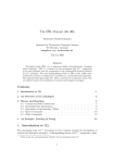
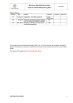
It may be shown that the water velocity at the height of the path AB is:
v = L x (TAB – TBA) / (TAB x TBA x 2 cosθ)
Where
TAB
TBA
L
θ
= Transit time from transducer A to B
= Transit time from transducer B to A
= Path length (distance between transducer A and transducer B)
= the angle between the “path” and the direction of flow.
1.2.5 Flow determination
The flow is determined by combining the water velocity measurements at the height of each
path with the cross section area defined by the water level and the shape of the channel. The
channel shape need not be the same as the projected width between the transducers. For
example if the transducers are mounted on piles inset from the channel sides. For the
purposes of flow determination the cross section area is divided into horizontal slices
determined by the channel bed, the heights of the paths themselves and the water surface
level.
The channel flow is the sum of the flows in each slice determined by the path velocity or
velocities and the area of the slice. The bottom slice is defined by the bed (which is assumed
not to move) and the top slice by the water surface (the level of which is measured by the
flowmeter). The slice widths may be determined by the projected width between the
transducers or by a separate table defining the cross section shape. The latter method is
used by the Sarasota 200.
There are 2 methods, mid section and mean section.
Section 1 INTRODUCTION Page 1-3
Thermo Fisher Scientific
Sarasota 200 Ultrasonic Multipath
Flowmeter
INTRODUCTION
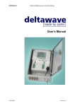
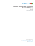
1.2.5.1 Mid section method
In the mid section method, the slice boundaries are defined by lines mid way between the
paths. The slice velocity is taken as that determined by the ultrasonic path within the slice and
the slice area as the product of the slice height and the (average) width. The upper boundary
of the top slice is the water surface. At the bottom, an additional slice is defined between the
bed and a line half way between the bed and the bottom path. This bottom slice has a
weighting factor, K, normally between 0.4 and 0.8 to allow for the slow moving water near the
bed. To reduce the uncertainty of this factor, the bottom path should be positioned as close to
the bed as practical.
Water Surface
Height HS
QS = V4 {HS − ½(H4 + H3)}W4
Top panel
Width W4
Path 4 Height H4
½(H4 + H3)
QS = ½V3 (H4 – H2)W3
Width W3
Path 3 Height H3
½(H3 + H2)
QS = ½V2 (H3 – H1)W2
Width W2
Path 2 Height H2
½(H2 + H1)
QS = ½V1 (H2 – H0)W1
½(H1+ H0)
Bottom panel
Height H0
Width W1
Path 1 Height H1
QS = ½kV1 (H1 – H0)WBed
Width WBed
Bed Height H0
Illustration of the mid section method for 4 paths
Section 1 INTRODUCTION Page 1-4
Thermo Fisher Scientific
Sarasota 200 Ultrasonic Multipath
Flowmeter
INTRODUCTION
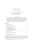
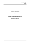
1.2.5.2 Mean section method
In the mean section method, the slice boundaries are defined by the path heights themselves.
The slice velocity is taken as the mean of the upper and lower paths which define the slice
boundaries. The upper boundary of the top slice is the water surface.
The velocity of the water surface, Vs, is given by:Vs = V4 + (V4-V3) x Ks(Hs-H4)/(H4-H3)
Where Ks is a multiplying factor normally between 0 and 1 to allow for the projection
of velocity to the water surface
Vs is limited to a value of V4 + (V4-V3) in the event of (Hs-H4) being greater than (H4-H3)
The lower boundary of the bottom slice is the bed. This bottom slice has a weighting factor,
KB, normally between 0.4 and 0.8 to allow for the slow moving water near the bed.
The mean section method is superior in cases where the paths are not near the slice centres,
but the mid section method handles the top slice better. The more paths that are deployed,
the less the differences matter.
The mean section method is illustrated in the following diagram:
Water Surface
Width WS
Surface Height HS
Qs = ½(VS + V4) x (HS – H4) x ½(WS+ W4)
W4
Path 4. Height H4
Qs = ½ (V4+ V3) x (H4 – H3) x ½(W4 + W3)
W3
Path 3. Height H3
Qs = ½ (V3 + V2) x (H3 – H2) x ½(W3 + W2)
W2
Path 2. Height H2
Qs = ½ (V2 + V1) x (H2 – H1) x ½(W2 + W1)
W1
Path 1 Height H1
Qs = ½V1(1 + kB) x (H1 – H0) x ½(W1 + WBed)
Wbed
Bed, Height H0
Illustration of the mean section method for 4 paths
Section 1 INTRODUCTION Page 1-5
Thermo Fisher Scientific
Sarasota 200 Ultrasonic Multipath
Flowmeter
INTRODUCTION
1.2.6 Path configurations
The simplest arrangement is to have a number of paths “in line” above each other. This
would be suitable for a channel of regular cross section shape, which is straight for a long
distance compared with its width (5 to 10 times).
Other configurations are often used in other circumstances. For example:
•
•
•
•
Crossed paths where there is uncertainty about the flow direction
Sloping paths where the depth is greater on one side compared with the other
Transducers inset from the banks
Reflected paths where transducers are on one side only and reflectors “bounce” the
sound pulses back from the far side. This method saves cable but increases path lengths
and is very sensitive to misalignment.
The Sarasota 200 flowmeter is capable of being configured for these and other situations.
For more complex configurations requiring more than 4 paths or compound channels, the
Sarasota 2000 offers more flexibility. Examples are:
•
•
•
Multiple sets of paths for compound channel shapes
V configuration used to divide the width because of size or uneven profile
Multiple channels
Please consult Thermo Fisher Scientific for examples and advice.
1.2.7 Transducer frequency
Transducers are manufactured with characteristic frequencies. These are in the range 1 MHz
to 250 kHz. For propagation reasons, the greater the path lengths the lower the frequency
and the larger the transducer. As a guide, path lengths below 10 metres would use 1MHz
transducers, 5 to 80 metres 500 kHz, 50 to 200 metres 250 kHz. These figures are for
guidance and the selection may be influenced by other factors relating to the application.
Where there is overlap, lower frequency transducers may be used to improve penetration in
conditions of high suspended solids provided there is sufficient depth and velocity.
Please consult Thermo Fisher Scientific for advice.
1.2.8 Minimum depth of water
In order to avoid reflections from the bed or surface causing distortion of the ultrasonic
signals, a minimum height of water is necessary above each path. This depends on the
transducer frequency and the path length.
Hmin
= 27 √ ( L / ƒ )
Where:
Hmin
L
ƒ
is the minimum height of water above the path, in metres
is the path length, in metres
is the transducer frequency, in Hertz
A similar restriction applies to the channel bed, particularly if it is smooth and reflects rather
than absorbs an acoustic signal. The minimum depth of water is therefore usually 2 x Hmin
Section 1 INTRODUCTION Page 1-6
Thermo Fisher Scientific
Sarasota 200 Ultrasonic Multipath
Flowmeter
INTRODUCTION
1.2.9 Performance estimates
ISO 6416 describes how to estimate the uncertainty of measurement in any particular
installation. Please consult Thermo Fisher Scientific for advice on this.
1.3 Implementation of the principles of operation in the Sarasota 200
The principles described in Section 1.2 are used by the Sarasota 200 subject to certain rules
as listed below. See also Appendix 1: GAFA Screens that describe in detail how the
flowmeter is programmed via a PC.
Flow
• There is a choice of mean or mid section method of flow calculation.
• The channel cross section shape is entered as a height/width table independent from the
path lengths and angles. (For rectangular or trapezoidal channels it is only necessary to
enter 2 points to define the channel.) The separate table allows the path velocities to be
applied to more accurate slice areas since the defined shape is used rather than a fixed
width for each slice as specified in the Standard.
• Where no path velocity is available, for example at low water height, flow may be inferred
from water level. This is done via a flow estimation table, which may be derived
empirically or by calculation.
Velocity
• The upstream velocity transducers are connected as shown in section 2.
• Path numbering is from the bottom.
• Paths are automatically brought into operation according to the water level and the
programmed minimum water cover.
• Paths entered as being at the same height are taken as crossed, otherwise they are
separate.
• Separate paths may be “normal” with transducers on each side or “reflected” with
transducers on one side only. The latter method saves cable but is not recommended
because of the increased path lengths and sensitivity to alignment.
• The velocities calculated by a pair of paths comprising a crossed path are averaged and
the average velocity used for the slice. The velocity calculated by a separate path is used
alone for the slice.
• When a velocity path fails, the slice boundaries automatically adjust to use only the
working paths.
• A failed path will show on the status indicated. The path status is a percentage of the
“instantaneous” transducer firings which result in successful reception. If this figure drops
below 12% the path is considered to have failed during the corresponding instantaneous
cycle time and is discarded for that cycle. This could be the result of a fault, misalignment
or obstruction.
• Only valid velocity paths which are in the water and covered by sufficient water to be
operating are used for the status indication.
• Each path may have a multiplying factor (“X Factor”) assigned to it. This will normally be 1
but may be different in exceptional circumstances for calibration purposes. An example of
when this might be is when the transducers are not exactly at the channel edges.
• Transducers in each velocity path may be set to operate simultaneously (the norm) or
sequentially. Simultaneous operation allows more measurements in a given time but
there is a small possibility of confusing a signal reflected back to the firing transducer with
one received from the opposite transducer.
Section 1 INTRODUCTION Page 1-7
Thermo Fisher Scientific
Sarasota 200 Ultrasonic Multipath
Flowmeter
INTRODUCTION
Water level
• Levels are combined in the following algorithm:
Only non-faulty measurements are used.
Highest and/or lowest are discarded until 3 remain.
The one furthest from the others is discarded leaving 2.
The remaining 2 measurements are averaged for arbitrated level if within an
acceptable band defined via the PC GAFA software.
If they are not within the acceptable band, level determination fails and flow cannot
be calculated.
If only 1 level measurement is installed or only 1 remains after arbitration, it is used
as the arbitrated level.
If not OK, level fails and flow cannot be calculated.
• Levels defined as valid but rejected by the algorithm will be indicated on the level status.
• Where the flowmeter is installed in a closed conduit which always runs full, the channel
shape is entered in the usual way but there is no need for a level measurement. The
flowmeter is programmed with a fixed level input corresponding to the top of the conduit.
Transducer and bed levels
All heights may be set to a fixed datum (local or national) or relative to mean bed level. The
former requires a height for the bed and avoids re-entering all path and level transducer
heights in the event of a change to the bed.
General
• “Instantaneous” means the average over the cycle time scale. This defaults to 10
seconds for fast response suitable for small channels. It may be set to 1 minute for
smoother averaging where the rate of change of flow conditions is slower.
• The average period is the time over which measurements are averaged for the purpose
of output or logged data. The average period cannot be shorter than the cycle time.
• At the data logging intervals, the averaged values of the selected data are stored.
• Analogue inputs will normally be linear. However, non linear characteristics may be
entered via the PC, see Appendix 1
• When operating on a 12 volt source, for example from a solar panel, power saving is
possible by using intermittent operation. Power consumption in normal and intermittent
modes is quoted in the Appendix 2: Specification.
Section 1 INTRODUCTION Page 1-8
Thermo Fisher Scientific
Sarasota 200 Ultrasonic Multipath
Flowmeter
2
SYSTEM COMPONENTS
2.1
Flowmeter system overview
SYSTEM COMPONENTS
•
The Thermo Scientific Sarasota 200 is an ultrasonic multi-path flowmeter, which complies
with ISO6416.
•
It employs state of the art technology to achieve excellent performance in conditions
which have previously been outside the scope of this type of instrument.
•
Smart transducer technology incorporating drive and receiver circuits optimises signal to
noise ratio and minimises losses. The smart circuits are located inside the transducer
housings except for the 1 MHz transducers. In that case they are in sealed in-line
housings known as Tboxes.
•
Automatic adjustment of receiver gain and transducer drive voltage (HT).
•
Low power consumption and intermittent modes make mains free operation feasible.
•
Multi-path operation, (up to 4) with multi-drop facility made possible by smart transducer
addressing to save cable.
•
Multiple water level inputs, subject to a maximum of 4 overall:
- up to 4 ultrasonic level transducers
- up to 2 auxiliary level gauges (via 4-20 mA inputs.)
•
Up to 2 analogue 4-20 mA outputs
•
System fault relay (volt free contacts)
•
2 programmable relays, 1 volt free contact, 1 high speed solid state. Programmable, for
example for alarms, status, totaliser pulses.
•
Two serial ports. RS232 for PC, RS232 for modem.
•
Internal data logger, 1 Mbyte capacity, programmable.
•
Water temperature measurement at each smart transducer (except 1 MHz transducers)
Section 2, SYSTEM COMPONENTS, Page 2-1
Thermo Fisher Scientific
Sarasota 200 Ultrasonic Multipath
Flowmeter
2.2
SYSTEM COMPONENTS
Family tree
The schematic diagram below is an illustration of a four path system.
Internal
Battery
option
External
power
source
11 to 30 V DC
External equipment
Auxiliary
depths
Power
control
Display
Transducer
interface
Central
Processor
inc.
2 x serial I/O
Inputs
2x
4-20 mA,
Outputs
2x
4-20 mA,
Relays
2 x VFC
u/s
d/s
Star
J box
Flow
Star
J box
Level
Trans. 1 u/s
Trans. 1 d/s
Trans. 2 u/s
Trans. 2 d/s
Trans. 3 u/s
Trans. 3 d/s
Trans. 4 u/s
Trans. 4 d/s
Level
Transducer
Option
Section 2, SYSTEM COMPONENTS, Page 2-2
Thermo Fisher Scientific
Sarasota 200 Ultrasonic Multipath
Flowmeter
SYSTEM COMPONENTS
2.3 Flowmeter contents and options
2.3.1 Flowmeter layout
s„˜„™•š„@RPP
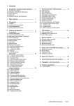
Fig 1 Sarasota 200 Flowmeter. Front panel view
This view of the Sarasota 200 shows:
• the LCD display (see section 2.3.2.3)
• the cable entry glands at the bottom
• the wall mounting brackets (see Appendix 2 for mounting dimensions)
Section 2, SYSTEM COMPONENTS, Page 2-3
Thermo Fisher Scientific
Sarasota 200 Ultrasonic Multipath
Flowmeter
SYSTEM COMPONENTS
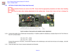
Fig 2 Sarasota 200 with lid open showing internal components
This view shows the connection panel protruding from the protective cover and the internal
battery in the bottom left corner.
The connection panel is part of the mother board which contains the input, output and power
management functions. It supports the main processor (CPU) card and the transducer
interface (TIF) card which plug in beneath the protective cover. The connection panel is
shown on a larger scale in Fig 3.
The internal battery allows operation to continue when the external power source has failed.
This is an optional facility which may only be fitted for certain external power sources. See
section 2.3.2.1.1
Section 2, SYSTEM COMPONENTS, Page 2-4
Thermo Fisher Scientific
Sarasota 200 Ultrasonic Multipath
Flowmeter
SYSTEM COMPONENTS
Fig 3. Connection panel - enlarged view.
This panel is where all the connections are made and where the power fuses are located.
Before making any connections the external power source and the internal battery (if fitted)
should be unplugged. The connections are in groups from left to right:
Power connections. See section 2.3.2.1.1
• PL15 – BATT. 2 pin plug for connection to the internal 12volt battery if one is to be fitted.
• PL16 – DC IN. 3 pin plug for connection to the external dc supply.
• Fuses FS1 and FS2
Relay connections. See Specification, Appendix 2
• PL9 – RELAY 2 - VFC, 3 pins, NC, Common and NO
• PL13 – RELAY 1 - SOLID STATE, 3 pins. See Appendix 2
• PL17 – FAULT RLY, 3 pins, NC, Common and NO
Status LED
Inputs See section 2.3.2.1.3
• PL10 – INP 1. 3 pin plug, 4-20 mA
• PL11- INP 2. 3 pin plug, 4-20 mA
Outputs See section 2.3.2.1.4
• PL18 – OUT 1. 4 pin plug, 4-20 mA
• PL19 – OUT2. 4 pin plug, 4-20 mA
Ultrasonic transducer connections. See section 2.3.2.1.2
• SK2 – LEVEL (L). BNC coaxial socket for ultrasonic water level transducer(s) if fitted.
• SK3 – UPSTREAM (A). BNC coaxial socket for upstream velocity transducer(s)
• SK6 – DOWNSTREAM (A). BNC coaxial socket for downstream velocity transducer(s)
• SK4 – UPSTREAM (B). BNC coaxial socket for upstream crossed path velocity
transducer(s) if fitted.
• SK7 – DOWNSTREAM (B). BNC coaxial socket for downstream crossed path velocity
transducer(s) if fitted.
Communications See section 2.3.2.1.7
SK5 – PC. 9 way D socket for RS232 serial link to PC
PL14 – MODEM. 9 way D plug for RS232 serial link to modem.
Digital See section 2.3.2.1.6
PL12, External connection W to 0V to wake up if in intermittent (external control) mode.
PL12 1 to 4 and PL20 – not used.
Section 2, SYSTEM COMPONENTS, Page 2-5
Thermo Fisher Scientific
Sarasota 200 Ultrasonic Multipath
Flowmeter
SYSTEM COMPONENTS
2.3.2 Internal components
The enclosure houses the following components
•
•
•
•
•
Mother board with power connections, connectors for transducers and peripheral devices.
Internal battery option.
Transducer interface card
Central processor card, with data storage, input/output and communications circuits
LCD display
2.3.2.1
Mother board
2.3.2.1.1 Power supply and internal battery option
The power supply input is 11 to 30 Volts DC (see specification in Appendix 2)
For operation from an AC source, an external adapter is required.
If the DC input is 15 Volts or more, the internal battery option may be fitted to allow operation
to continue in the event of power failure. The internal battery is automatically charged by the
power supply when external power is being supplied.
Power consumption and the period of operation from the internal battery option depend on the
mode of operation and are given in the specification.
The fuse values are both T1A.
2.3.2.1.2. Transducer connections
For an in-line configuration of velocity paths there will be 2 star junction boxes, 1 for each
transducer array. The coaxial cable from the upstream star box terminates at SK3. The
coaxial cable from the downstream star box terminates at SK6.
For a crossed configuration of velocity paths there will be 4 star junction boxes, 1 for each
transducer array. The coaxial cable from the upstream left star box terminates at SK3 and the
downstream right at SK6. The coaxial cable from the upstream right star box terminates at
SK4 and the downstream left at SK7.
If an upward facing depth transducer is being used, the coaxial cable from it terminates at
SK2.
Section 2, SYSTEM COMPONENTS, Page 2-6
Thermo Fisher Scientific
Sarasota 200 Ultrasonic Multipath
Flowmeter
SYSTEM COMPONENTS
2.3.2.1.3. Depth input signals
These will normally be from auxiliary depth gauges via 4-20 mA. Common examples are
pressure transmitters and downward facing ultrasonic devices. The Sarasota 200 can accept
up to 2 inputs of this type via PL10 and PL11. The power for the 4-20 mA loop can come from
the Sarasota 200 or from the external device.
Pin
1
2
3
Signal
name
0V
IN
+V
Connect for internal
loop power
N/C
4-20mA 4-20mA +
Connect for external
loop power
4-20mA 4-20mA +
N/C
Comment
Applies to
INP 1 on PL10 and
INP2 on PL11
2.3.2.1.4. Output signal connections (Analogue)
There are 2 analogue output connectors, OUT1 PL18 and OUT2 PL19. The functions to be
output and their ranges are programmable. The power for the 4-20 mA loop can be internal,
from the Sarasota 200 in which case the outputs are not isolated, or from the external device
in which case they are isolated.
Pin
1
2
3
4
Signal
name
0V
+
+V
Connect for internal
loop power
4-20mA 4-20mA +
Link 3 – 4
Connect for external
loop power
4-20mA 4-20mA +
Comment
Applies to
OUT1 PL18 and
OUT2 PL19
2.3.2.1.5. Relay connections
There are 3 relay connections
PL17 System fault relay. This relay has Normally Open (NO), Normally Closed
(NC) and Common (C) contacts. It operates when there is a fault which prevents flow
being calculated. This will occur when no velocity path is functioning or when no
depth is functioning.
PL13 Relay 1. Solid state relay, see Appendix 1, Screens. Although relay 1 may be
programmed for any of the available functions, its faster switching rate makes it
particularly suited for a pulsed output to an external totaliser. See appendix 2
Specification.
PL9
Relay 2. Programmable, see Appendix 1, Screens. This relay has Normally
Open (NO), Normally Closed (NC) and Common (C) contacts.
For example, relay 2 could be programmed as a high flow alarm to switch on at a high flow
and off again at a lower value (hysteresis).
Section 2, SYSTEM COMPONENTS, Page 2-7
Thermo Fisher Scientific
Sarasota 200 Ultrasonic Multipath
Flowmeter
SYSTEM COMPONENTS
2.3.2.1.6. Digital signal connections
When in intermittent mode under external control (see Appendix 1, screens), the external
controlling device must apply a connection between W and OV of PL12 to switch the
Sarasota 200 on.
PL12 - 1 to 4 and PL20 – not used at present.
2.3.2.1.7 Serial communications connections
Serial communications are controlled by the CPU (see 2.3.2.2). It has 2 ports and
connections are made via SK5 and PL14 on the mother board as follows:
•
•
SK5 - RS232 via 9 way D connector (female). See Fig 3. This port is used for connection
to a PC for setting up, diagnostics and downloading logged data.
PL14 - RS232 via 9 way D connector (male). See Fig 3. This port is used for connection
to a modem for remote access for programme alterations, diagnostics and downloading
logged data.
Pin (F)
2
3
5
Signal
TxD
RxD
0V
Comment
SK5 – RS232, PC connection
9 way female D connector
Pin (M)
1
2
3
4
5
7
8
9
Signal
CD
RxD
TxD
DTR
0V
RTS
CTS
RI
Comment
PL14 RS232, Modem connection
9 way male D connector
2.3.2.2
Central processor (CPU)
The central processor carries out the control and timing functions, stores and runs the
operating program and stores the data logs.
It controls the two serial i/o ports, see 2.3.2.1.7.
The CPU card plugs into the mother board by removing the cover.
There are no operator settable links on the CPU.
2.3.2.3
LCD display
The LCD has 2 lines of 20 characters to display measurements, computed results and
diagnostic information. (see Section 2.5).
The LCD card is located on the opening lid of the enclosure.
Section 2, SYSTEM COMPONENTS, Page 2-8
Thermo Fisher Scientific
Sarasota 200 Ultrasonic Multipath
Flowmeter
2.3.2.4
SYSTEM COMPONENTS
Transducer interface card (TIF)
The flowmeter has a single TIF which plugs into the mother board by removing the cover. The
transducer connections are made via internal cables to the mother board.
The jumper links on the card should not be altered. When a TIF is changed during service,
the replacement must have the same links set.
2.3.2.5
AC Power adapter module
The adapter is an external module. It allows the Sarasota 200 to be operated from AC mains
electricity between 90 and 264 Volts and between 47 and 63 Hz.
Section 2, SYSTEM COMPONENTS, Page 2-9
Thermo Fisher Scientific
Sarasota 200 Ultrasonic Multipath
Flowmeter
2.4
SYSTEM COMPONENTS
Ultrasonic transducers
Each velocity path requires two transducers and each ultrasonic depth requires one.
The transducers are available in a number of frequencies. See Section 1.2.7 for frequency
selection. The frequency of the ultrasonic depth transducer, if used, is not normally critical.
1 MHz is usually used if the velocity transducer frequency is 1 MHz or 500 kHz otherwise.
The diameter of the transducer is different for different frequencies. This is to maintain the
angular spread of the beam, which is a function of frequency and diameter.
The transducers for the Sarasota 200 are “smart”, with local circuits for the drive voltage (HT)
generation and the receiver amplifier built in to minimise losses and optimise signal-to-noise
ratio. In the case of the 1 MHz transducers the size of the transducer is limited and the local
circuit is separated from the transducer in a potted in-line housing called a “Tbox”,
Transducers are wired to the flowmeter using the multi-drop method, via “star” junction boxes
in each transducer array. Up to 4 transducers may be joined together in this way.
The maximum capacity with multi-drop is 4 paths and 4 ultrasonic depths. (Auxiliary depths
may also be used via 4-20 mA inputs).
The transducers connected to each star box must be pre-programmed with different
addresses from 1 to 4 to enable each one to be operated separately by the flowmeter.
Specialist equipment is necessary to programme the transducers and it is usual for them to
be supplied with specified addresses.
2.4.3 1 MHz transducers
For use with path lengths up to 10 metres. In cases where serious attenuation is anticipated
(for example, sewage) it is recommended that the use be restricted to 5 metres and a lower
frequency be used above that. Of course the lower frequency requires a greater depth of
water in which to operate and this must be taken into account (see Section 1).
An in-line Tbox is fitted in line with each transducer.
The co-axial cable from the T box must be connected to a star box or extended to run directly
to the flowmeter. Coaxial cables to the flowmeter enclosure are usually made up on site.
Cables may be supplied to length with made up ends if specified with the order. However this
often makes the installation more difficult where there is the need to pull cables through ducts.
2.4.3 1 MHz intrinsically safe (IS) transducers
1 MHz transducers are available for use in hazardous areas which have atmospheres with a
risk of explosion. The IS specification is given in Appendix 2, specification. The transducer is
internally different from the standard one and a special barrier is wired between it and its
Tbox. The transducer and connecting cable can be used in the hazardous area but the barrier
and all other electronic parts must be located in safe areas.
Section 2, SYSTEM COMPONENTS, Page 2-10
Thermo Fisher Scientific
Sarasota 200 Ultrasonic Multipath
Flowmeter
SYSTEM COMPONENTS
2.4.3 500 kHz transducers
For use with path lengths above 10 metres. In cases where serious attenuation is anticipated
(for example, sewage) it is recommended that 500 kHz transducer be used above 5 metres.
At the upper end, they may normally be used up to 80 metres. For cases where serious
attenuation is anticipated, lower frequency transducers should be used for paths above 50
metres.
The 500 kHz transducers have the HT and signal amplifiers built in. They are connected
directly to the flowmeter or via star boxes. If ultrasonic depth transducer(s) are being used, it
is usual to use 500 kHz frequency when that frequency is being used for water velocity
measurement.
The transducers are supplied with 5 metres of cable which is connected to a star box or
extended to run directly to the flowmeter. Coaxial cables to the flowmeter enclosure are
usually made up on site. Cables may be supplied to length if so ordered with made-up ends.
However, this often makes the installation more difficult where there is the need to pull cables
through ducts.
The 500 kHz transducer also has a temperature sensor built in allowing water temperature at
each transducer to be recorded by the Sarasota 200.
2.4.4 Lower frequency transducers
Consult Thermo Fisher Scientific about low frequency transducers for path lengths above 80
metres or where conditions might attenuate higher frequency signals.
If ultrasonic depth transducer(s) are being used, it is usual to use 500 kHz frequency when
lower frequency transducers are being used for water velocity measurement.
2.4.5 Maximum cable lengths
Item
From
To
Flowmeter
Max
length
300 m
1
3
500 kHz transducer
(velocity or depth)
1 MHz TBox
(velocity or depth)
Star box
Direct connection
Flowmeter
300 m
Direct connection
Flowmeter
300 m
500 kHz transducer
Star box
5m
5
1 MHz
Tbox
1.5 m std.
6
Tbox
Star box
5m
7
500 kHz depth transducer
Star box
50 m
8
1 MHz depth TBox
Star box
50 m
9
10
1 MHz IS
Barrier
Barrier
Tbox
Multi-drop
(but see depth options items 6 & 7)
Multi-drop
(but see depth option item 6)
Longer separations may be supplied.
Consult factory.
Multi-drop
(but see depth option item 7)
Multi-drop depth option
(star box max 5 m from flowmeter)
Multi-drop depth option
(star box max 5 m from flowmeter)
Consult factory
4
1m
2
Section 2, SYSTEM COMPONENTS, Page 2-11
Comment
Thermo Fisher Scientific
Sarasota 200 Ultrasonic Multipath
Flowmeter
2.5
SYSTEM COMPONENTS
Controls and displays
Fig 1 shows the layout of the front panel. It contains the liquid crystal display (LCD).
Electronic access to the flowmeter is by means of a (laptop) PC via the serial connector
locally or remotely via a modem. This allows the operator to:•
•
•
•
•
•
•
•
programme the flowmeter with site data. For example. path lengths, angles, heights
set up the inputs and outputs (including simulation for test purposes)
set up the relay functions and values on which they switch
set up the information to be displayed cyclically on the flowmeter LCD
display ultrasonic waveforms
display measurements and results
display diagnostic data
download stored data
The information being displayed cycles through items selected from a menu on a PC screen.
2.6
Software & firmware
There are 2 types of software:
•
•
The internal pre-loaded operating software, normally called “firmware”
The PC software for communicating with the flowmeter, called “GAFA”
2.6.1 Operating firmware
The flowmeter is supplied with the operating firmware already loaded. It would not normally
be necessary to re-load the firmware. In the event that new firmware is to be loaded, Thermo
Fisher Scientific will provide the procedure or carry out the operation. Alternatively upgrades
may be loaded remotely by Thermo Fisher Scientific via a modem.
2.6.2 “GAFA” PC software
GAFA software runs on a PC under Windows. This allows communication with the flowmeter:•
•
Via the RS232 PC port on the mother board
Remotely via a modem connected to the RS232 MODEM port on the mother board
See Appendix 1: GAFA Screens.
2.7
Documentation
In addition to the hardware described above, and possible peripheral equipment, the following
documentation may also be supplied:
•
•
•
•
•
•
A copy of this manual (additional paper or electronic copies may be supplied)
Site specific data (Appendix A4: Site Data). Configuration and program data completed
by installation and commissioning engineers.
Site specific drawings – transducer mounts, site layout, civil details (if part of contract)
Certificate of conformity (specific test sheets available on request)
Certificate of approval for Quality Management System
On site calibration certificate (if included in the installation contract)
Section 2, SYSTEM COMPONENTS, Page 2-12
Thermo Fisher Scientific
Sarasota 200 Ultrasonic Multipath
Flowmeter
PERIPHERAL EQUIPMENT
3 PERIPHERAL EQUIPMENT
3.1
Additional items
A number of additional items will be required to complete a flowmeter system. These may
include:•
•
•
•
•
Hardware to be installed in the channel on which to mount the transducers.
Auxiliary depth gauge(s)
Kiosk to house the flowmeter
Communications equipment – for example modems, telemetry outstations, GSM
modems.
Power supplies, for example solar power systems.
plus, often, some civil work for cable ducts, supporting piles etc.
The additional items are often supplied and installed by Thermo Fisher Scientific as part of
the contract, in which case details will be included in Appendix 4: Site Data Book.
3.2
Transducer mounting hardware
Thermo Fisher Scientific has extensive experience of transducer mounting system design and
maintains a comprehensive computerised library. Please consult Thermo Fisher Scientific for
a quotation to design and supply a suitable system.
Section 3, PERIPHERAL EQUIPMENT, Page 3-1
Thermo Fisher Scientific
Sarasota 200 Ultrasonic Multipath
Flowmeter
PERIPHERAL EQUIPMENT
This page is blank
Section 3, PERIPHERAL EQUIPMENT, Page 3-2
Thermo Fisher Scientific
Sarasota 200 Ultrasonic Multipath
Flowmeter
4
INSTALLATION
4.1
Safety
INSTALLATION
SAFETY NOTICE
The installation of the Thermo Scientific Sarasota 200
flowmeter may involve a number of steps which require
special skills, training and special equipment. Examples
include:
•
•
•
•
•
•
•
Electrical installation
Working on construction sites
Working near water (may be deep or fast flowing)
Lifting equipment
Working at height
Working from boats
Confined space working
It is recommended that prior to the installation the installer
should write a method statement detailing:
•
•
•
•
•
•
•
•
The scope and purpose of the work,
The steps in the operation,
Interaction with others,
The personnel to be involved,
Their qualifications for the work,
Protective clothing and equipment,
Machinery, tools etc.
Emergency contacts and procedures.
A risk assessment should be carried out and both the
method statement and risk assessment should be
approved by the person responsible for Health and Safety
on the site.
Thermo Fisher Scientific accepts no responsibility for the
safety of personnel other than its own employees in the
installation and commissioning of the Thermo Scientific
Sarasota 200 flowmeter and accessories supplied.
Section 4 INSTALLATION Page 4-1
Thermo Fisher Scientific
Sarasota 200 Ultrasonic Multipath
Flowmeter
4.2
INSTALLATION
General
It is usually necessary for some preparatory work to be carried out prior to installation of the
flowmeter system. This work is often performed under a separate contract and typically
includes:•
•
•
•
•
Installation of supporting structures for transducer mounts, for example, piles in a river,
brackets on concrete channel walls.
Installation of ducts or cable tray for the interconnecting cables.
Installation of a suitable housing for the flowmeter and peripheral equipment. This could
be an existing building or a kiosk.
Provision of a power supply.
Provision of a PSTN connection.
The installation of the equipment on site follows the above. It is normal practice to carry out a
risk assessment and to write a method statement to be agreed by the client before starting
work. The installation work is often restricted to times when suitable site conditions apply.
It is recommended that the installer of the flowmeter should inspect the preparatory work prior
to mobilising resources for the installation.
4.3
Unpacking and laying out
If site and general assembly drawings were specified as part of the supply contract they will
normally have been supplied and accepted prior to delivery of the equipment. The drawings
will be a useful guide to checking the inventory of equipment delivered.
The equipment supplied should be carefully unpacked and checked for content and damage.
The transducers may have been supplied in rack assemblies ready to be fixed to the
supporting structure. There will normally be two or four racks (for in-line or crossed paths). In
large channels or those with complex shapes, there may be more than two racks, for
example, in a stepped channel with a low level channel and a wider high one.
If the racks have not been assembled, this may be carried out on site according to the
assembly drawings.
It is important to check that sufficient cable has been supplied for connecting transducers and
that suitable fixings for all the items have been supplied or separately procured.
4.4
Installing transducer assemblies
WARNING – Installing transducer racks may involve working near deep or
contaminated water and/or in confined spaces. Appropriate precautions and suitably
qualified personnel should be used.
The transducer rack assemblies should be installed in their prepared positions according to
the drawings and method statements.
Care must be taken not to damage the coaxial cables during this operation.
See Section 2.4 for transducer and junction box configuration.
Depth gauge transducers or transmitters may be fitted to one or more of the transducer racks
or have a separate fitting.
Section 4 INSTALLATION Page 4-2
Thermo Fisher Scientific
Sarasota 200 Ultrasonic Multipath
Flowmeter
4.5
INSTALLATION
Connecting transducers to flowmeter
Cables for the ultrasonic transducers should be labelled for identification, cut and pulled
through the ducts or attached to trays and run back to the flowmeter. Connectors should be
fitted to each end according to the instructions supplied with the connectors.
Where 1 MHz transducers are being installed, the connections are via the transducer boxes
(see Section 2.4.1) which are fitted at the rack assemblies.
Cables for depth gauges other than Sarasota ultrasonic transducers should also be pulled
back to the flowmeter. Generally, if the depth gauge is a pressure transmitter, the attached
cable will be supplied long enough for this purpose without joining. Care must be taken to
ensure that the transducer vent, which is part of the cable, is open to the atmosphere and in
no danger of becoming blocked or submerged in water.
The transducer cables are to be terminated at the flowmeter end and plugged in to the
flowmeter connection panel as shown in Section 2.3.1.
Ultrasonic path numbers are as shown, numbered from the lowest path. If 2 paths are at the
same height the firmware will take them as crossed for the purposes of slice allocation and
flow calculation (see 1.2.5).
4.6
Transducer alignment
At this stage it is usual practice to align the transducers. Each transducer should point at its
partner to within ±1o. The method used will vary according to the conditions.
• Pre-set alignment derived from construction drawings.
• Visual methods involving pointers and sighting arrangements.
• Low power laser methods.
If the transducers are in the water, only the first of these may be possible and final adjustment
should then be carried out by adjustments to maximise signals during commissioning.
4.7
Output connections
Output signals should be wired to the peripheral devices according to the connection tables
given in section 2.3. In some cases standard cables will have been provided, eg RS232, or
pre-made cables will have been ordered as part of the contract.
Note For compliance with EMC emissions control, I/O cables should be screened and the
screen connected to a 0V pin. Where the connector is a ‘D’ type connector, the screen may
alternatively be connected to the connector body if metal.
4.8
Power Connection
Connection should be made to the external power source according to local or national
regulations. The flowmeter is supplied with a standard 11 to 30 volt DC input with an optional
external mains convertor for connection to an AC source in the range 90 to 264 volt AC, 47 to
63 Hertz. This may be connected to the power outlet via a plug or, more usually via a
switched spur. This work should be carried out by a person with the appropriate qualifications.
Section 4 INSTALLATION Page 4-3
Thermo Fisher Scientific
Sarasota 200 Ultrasonic Multipath
Flowmeter
INSTALLATION
This page is blank
Section 4 INSTALLATION Page 4-4
Thermo Fisher Scientific
Sarasota 200 Ultrasonic Multipath
Flowmeter
5
COMMISSIONING
5.1
Site dimensions
COMMISSIONING
If this information is not already available, it will be necessary to carry out a dimensional
survey of the installed transducers and the channel in order to programme the flowmeter. It
will be necessary to determine the following:•
•
•
•
•
length, angle and the heights of each path,
average cross section profile, if different from that defined by the paths,
mean bed level (MBL),
height offset of the level transducers and,
relationship between the local heights and a fixed datum if not working with respect to
MBL.
This manual does not cover surveying techniques. However, for small sites physical
measurements are easily carried out by means of a tape measure. Angles may be
determined by triangulation.
5.2
Powering up
Check that the flowmeter has been connected up correctly and the cards are plugged in
securely.
Load the GAFA software into a PC and plug in to the PC serial port.
Switch on the power source.
The LCD will be activated though the display may be meaningless at this stage.
5.3
Programming
The flowmeter should be programmed via the PC as described in Appendix 1: GAFA
Screens. The programme details should be recorded to become part of Appendix 4: Site
Data.
Appendix 4: Site Data is a useful checklist covering all programmed data, some of which may
not be required for any particular site.
5.4
Setting up
5.4.1 Velocity paths
Select “Manual” and set the gain and voltage for each path to obtain a clean waveform and
detection point.
5.4.2 Ultrasonic levels
Select “Manual” and set the gain and voltage for each level to obtain a clean waveform and
detection point.
Section 5, COMMISSIONING Page 5-1
Thermo Fisher Scientific
Sarasota 200 Ultrasonic Multipath
Flowmeter
COMMISSIONING
5.4.3 Auxiliary levels – analogue input
Set the input range. This allows the input to be linearised, but most level devices will be
sufficiently linear and only need 2 points to define the input. On the table, define 4 mA as the
minimum, 20 mA as the maximum and enter the depth offset (level above datum).
5.5
Outputs
The outputs are selected from analogue and relays.
Analogue outputs may be forced to a value of mA which may be entered via the PC. See
“Loop Test”, Appendix 1, A1.4.1.2. This is a valuable tool for setting up the link to peripheral
equipment. The forced values may be confirmed by a calibrated multi-meter.
Correspondence between the displayed selected parameter value and the output should be
checked. It is possible to force the outputs by temporarily changing the set-up, for example
changing the level datum will affect not only the apparent level measurement but also the
flow.
Alarm thresholds may be altered to check relay operation.
Alarm outputs may be checked by a calibrated multi-meter and verified as being received by
the destination device.
Section 5, COMMISSIONING Page 5-2
Thermo Fisher Scientific
Sarasota 200 Ultrasonic Multipath
Flowmeter
6
CALIBRATION/
VERIFICATION
CALIBRATION/VERIFICATION
Flowmeters of this type do not normally require calibration. Exceptions are where there are
significant unmeasured areas, for example, behind transducers, or where local conditions
might create atypical velocity profiles and a small number of velocity paths are deployed. See
Section 1: Introduction and Appendix 3: References.
However, it is normal to carry out periodic checks to verify the overall performance of the flow
determination.
Whether for calibration or verification purposes, the comparison method to be used will be the
same and will depend on the site.
Reference is made to ISO 748 for details of methods. See Appendix 3: References.
The most common method used is by current metering using a calibrated rotating element or
electromagnetic current meter. Recently the use of an acoustic Doppler profiler (ADP) has
become more common for this purpose. This has enabled the checking process to become
much quicker and, where high flows in rivers are concerned, safer too.
Care should be taken to use repeated checks and to minimise the experimental uncertainties
which could otherwise be greater than the uncertainty of the ultrasonic flowmeter.
Section 6 CALIBRATION/VERIFICATION Page 6-1
Thermo Fisher Scientific
Sarasota 200 Ultrasonic Multipath
Flowmeter
CALIBRATION/
VERIFICATION
This page is blank
Section 6 CALIBRATION/VERIFICATION Page 6-2
Thermo Fisher Scientific
Sarasota 200 Ultrasonic Multipath
Flowmeter
7
MAINTENANCE
MAINTENANCE
There is little maintenance as such relating to the flowmeter itself. However, the river or
channel must be kept free of weed, silt and other obstructions to avoid interruption of the
ultrasonic paths or changing the cross section area which would affect the accuracy of flow
determination.
Periodic checks on the functioning of the flowmeter and verification of the flow as calculated
are recommended.
7.1
Channel maintenance
7.1.1 Weed
•
•
•
If weed tends to grow in the channel, it must be kept cut.
Weed must be kept clear from between the transducer arrays where it may stop the
passage of sound between the transducers.
Weed should also be controlled on the approach to the gauged section and immediately
downstream of it where its presence could distort the velocity profile.
The user must decide on the seasonal cutting regime to suit the channel.
7.1.2 Profile
Periodically the channel shape should be checked to determine whether it has changed since
the flowmeter was programmed. It is particularly important to check the bed where silt might
have been deposited or scouring could have occurred.
Changes may be required to the programmed channel shape or mean bed level.
In serious cases, it may be necessary to dredge the channel, taking care not to damage the
transducers.
The user must decide on the checking regime to suit the channel.
7.1.3 Debris
Under high flow conditions it is not uncommon for debris to be washed along the channel.
Whilst the design of the transducer supports should be such as to minimise the risk of
snagging this debris, separate deflectors or devices intended to capture it may be employed.
If the channel is prone to this phenomenon, the user must instigate an appropriate debrisclearing regime.
7.2
Flowmeter maintenance
There are no parts requiring maintenance except that the transducers should be checked
occasionally for a build-up of surface coating, for example by grease, and for misalignment
caused by physical shocks. These checks may be carried out along with the channel
maintenance.
Normally it is possible to obtain advance warning of problems by checking the signal quality.
This may be done on site or remotely via GAFA (Appendix 1: GAFA Screens).
Section 7, MAINTENANCE Page 7-1
Thermo Fisher Scientific
Sarasota 200 Ultrasonic Multipath
Flowmeter
7.3
MAINTENANCE
Routine checks
7.3.1 Remote
Remote checks of operation of all velocity paths and depths are easily carried out via GAFA.
It is recommended that a monthly routine should be set up to handle this.
If the flowmeter is fitted with the relay option, one of the relays may be programmed to initiate
an early warning call via a telemetry outstation.
7.3.2 On site
It is recommended that regular checks be made on site. These should include:
• A visual observation of the equipment in the channel and the flowmeter.
• A functional check of the operation of the paths, levels and outputs.
• A check on the operation of the internal battery.
• A verification of calculated flow by a comparison method, see Section 6: Calibration
Any corrective work should be taken at the time if possible or reported for subsequent action.
Section 7, MAINTENANCE Page 7-2
Thermo Fisher Scientific
Sarasota 200 Ultrasonic Multipath
Flowmeter
APPENDIX 1 GAFA PC SOFTWARE
APPENDIX 1 “GAFA” PC SOFTWARE
A1.1 Screen organisation chart
A1.2 Main Screen
File
A1.3 View
A1.3.1
Flow & Level
A1.4 Config
A1.5 Log
A1.4.1
Station Config
A1.6 Waveform
A1.5.1
Logging
A1.3.2
A1.4.1.1
A1.5.1.1
Velocity Paths
System
Log Config
A1.7 Password
A1.6.1
Waveform
Capture
Help
Enter Password
A1.4.1.2
A1.3.3
I/O Allocation
Flow Meter Status
A1.4.1.3
Relays
A1.4.1.4
Comms
A1.4.2
Channel Config
A1.4.2.1
Channel
A1.4.2.2
Velocity Path
A1.4.2.3
Level
A1.4.2.4
Profile
A1.4.2.5
Flow Est
A1.4.3
Read Gauge Config
A1.4.4
Write Gauge Config
Appendix 1 GAFA PC Software Page A1-1
Thermo Fisher Scientific
Sarasota 200 Ultrasonic Multipath
Flowmeter
APPENDIX 1 GAFA PC SOFTWARE
A1.2 Main Screen
Notes
•
This is the main screen showing current measurements and status.
•
Measurements displayed on this screen are subject to averaging as set up on the
“Station Configuration - System” screen A1.4.1.1.
•
Cumulative volume is the total volume passed since last reset via the “Station
Configuration – System” screen A1.4.1.1.
•
If more than 1 level input is used, the Level displayed on this screen is the combination
subject to the arbitration rules given in section 1 of this manual.
•
Average temperature is taken from all sensors with transducers that are in the water.
Transducers above the water are not included. Temperature is measured by sensors in
the transducer smart electronic circuits. For 1 MHz transducers this will often not be
water temperature since the circuits are in Tboxes which may be out of the water.
Individual temperatures may be viewed on the “Velocity Paths” screen A1.3.2.
•
Data presented on the screen is automatically refreshed every 30 seconds.
•
Click on “Refresh” to update immediately.
•
Click on menu bar across the top of the screen to obtain drop down menus for other
screens.
•
Pressing Escape on the PC keyboard when in other screens causes a return to the
previous screen.
Appendix 1 GAFA PC Software Page A1-2
Thermo Fisher Scientific
Sarasota 200 Ultrasonic Multipath
Flowmeter
APPENDIX 1 GAFA PC SOFTWARE
A1.3 “View” Screens
A1.3.1 (View) Flow and Level
Notes
•
“Instantaneous” data is based on the measurement cycle of 10 seconds or 1 minute as
set on the “Station Configuration – System” screen A1.4.1.1.
•
“Average” is based on the period set on the “Station Configuration – System” screen
A1.4.1.1.
•
“Daily Mean” is the flow for the previous 24 hour period to the DMD time as set on the
“Station Configuration – System” screen A1.4.1.1. The Daily Mean value will only change
at the set time.
•
“Cumulative Total” volume is from the date indicated as set via the “Station Configuration
– System” screen A1.4.1.1.
•
“Cumulative, Today” is from the DMD time to the present time.
•
“Level Inputs” are the instantaneous separate inputs used to calculate the average level.
•
Click on “Refresh” to update the display.
•
Click on X or Cancel or press the escape key to return to the Main screen.
Appendix 1 GAFA PC Software Page A1-3
Thermo Fisher Scientific
Sarasota 200 Ultrasonic Multipath
Flowmeter
APPENDIX 1 GAFA PC SOFTWARE
A1.3.2 (View) Velocity Paths
Notes
•
“Success” indicates the proportion of “flights” of sound pulses resulting in acceptable
signals received.
•
“VOS” is the velocity of sound measured by each path. It is the path length divided by
the transit time.
•
“Velocity” is the water velocity calculated for each path. (see Section 1 of the manual)
•
“TOF” is the ultrasonic time of flight or transit time
•
“Diff” is the difference in transit times between the upstream and downstream
directions.
•
“Temp” is the temperature measured by sensors in the transducer smart electronics.
This will be water temperature for transducers other than 1 MHz immersed in water.
•
Click on “Refresh” to update the displayed data.
•
Click on X or Cancel or press the escape key to return to the Main screen.
Appendix 1 GAFA PC Software Page A1-4
Thermo Fisher Scientific
Sarasota 200 Ultrasonic Multipath
Flowmeter
APPENDIX 1 GAFA PC SOFTWARE
A1.3.3 (View) Flow Meter Status
Notes
•
“Software IDs” are the issue numbers of the software loaded on the system cards
•
“CPU Power Rails” show the values of the internal supply voltages.
•
“Status” conditions are red for a fault and green for OK.
•
For “Channel” status, “Level” is red if all the levels are faulty and “Path” if all the paths
are faulty. These are “fatal” conditions that could prevent flow being calculated. Under
these conditions, a flow figure could still be estimated using the flow estimation table,
See A1.4.2.5
•
“Relay Status” indications depend on conditions as set on the “Station Configuration –
Relay” screen.
•
Click on “Refresh” to update displayed data.
•
Relays may be reset on this screen or alternatively on the “Station Configuration Relays” screen A1.4.1.3.
•
Click on X or Cancel or press the escape key to return to the Main screen.
Appendix 1 GAFA PC Software Page A1-5
Thermo Fisher Scientific
Sarasota 200 Ultrasonic Multipath
Flowmeter
APPENDIX 1 GAFA PC SOFTWARE
A1.4 Configuration screens
A1.4.1 Station Configuration
A1.4.1.1 System
Notes
This screen is used to
•
Set the site name or number if used (ID)
•
Select the flow calculation method (See section 1 of the manual.)
•
Select the measuring cycle time (default 10 seconds)
•
Set the averaging period. This is a rolling average, updated at each measuring cycle.
•
Set the time of day for the Daily Mean Discharge (daily mean flow) calculation.
•
Set the date and time
•
Select the power source (used by the power supply alarm threshold circuits).
•
Select low power control (if required) via external interrupt or internal timer.
•
Select the units of measurement.
•
Select the items to be displayed
on the LCD by clicking on “Edit
Display List” (see picture, right)
•
“Reset Totals” clears the
cumulative flow total.
•
Write selection to Sarasota 200
by clicking “Write to Gauge”.
•
Additional data is for changing
the password (See A1.7) and
altering the date format.
•
Click on X or press the escape
key to return to the Main screen.
Appendix 1 GAFA PC Software Page A1-6
Thermo Fisher Scientific
Sarasota 200 Ultrasonic Multipath
Flowmeter
APPENDIX 1 GAFA PC SOFTWARE
A1.4.1.2 (Station configuration) I/O Allocation
Notes - Level Inputs
•
Click on “Allocate” to get pop up screen (right)
•
Up to 4 levels in total may be selected
•
For each one, select a type :
Not Used if none allocated to that level input
USL for an ultrasonic upward facing
transducer. For this selection, a multi-drop
address between 1 and 4 must be specified
via the Input drop down. If there is only 1 USL,
use Input 1 on the drop down.
Analogue for 4-20 mA auxiliary depth inputs.
For this selection, input 1 or 2 must be
selected on the drop down.
Fixed for a channel where the depth does not
change, e.g a full pipe.
•
•
•
Click on “Write” to confirm selected levels to the Sarasota 200.
Click on “Exit” to abandon selection.
See “Channel Configuration – Level” A1.4.2.3 to set up the selected levels.
Appendix 1 GAFA PC Software Page A1-7
Thermo Fisher Scientific
Sarasota 200 Ultrasonic Multipath
Flowmeter
APPENDIX 1 GAFA PC SOFTWARE
Notes – U/S Path Inputs
•
•
Click on “Allocate” to get pop up screens (right)
Up to 4 velocity paths in total may be selected
•
If the “200 Cross Path Application” is not ticked,
the paths will be allocated to an in-line
configuration using connectors A only.
Paths, numbering from the bottom, shall be
allocated to A connectors (upstream and
downstream) via addresses 1 to 4
•
•
•
•
•
•
If the “200 Cross Path Application” is checked
(right), the allowable configurations are:
- up to 2 paths allocated to A and 2 to B
- up to 3 paths allocated to A and 1 to B
A relay may be selected for any path or paths.
The relay will then operate in the event of a fault
on any of the paths for which the relay is selected
Click on “Write” to confirm selected levels to the
Sarasota 200.
Click on “Exit” to abandon selection.
See “Channel Configuration – Velocity Paths”
(A1.4.2.2) to set up the selected paths.
Notes – Analogue Outputs
• There are 2 analogue (4-20 mA) outputs.
• Click on each one to get the drop down and allocate to functions:
Flow
Level
Velocity
DMD
• Ranges are set up on this screen for the
functions selected by entering numbers for
“Zero” and “Full Scale”
•
Click on “Write” to confirm selected analogue
outputs to the Sarasota 200.
•
•
Click on “Loop Test” to obtain pop up (right).
Select output 1 or 2 and the value of mA to be
applied to the output for test purposes. Before
using loop test, the analogue output must be
set to “None” on the drop down menu.
Appendix 1 GAFA PC Software Page A1-8
Thermo Fisher Scientific
Sarasota 200 Ultrasonic Multipath
Flowmeter
APPENDIX 1 GAFA PC SOFTWARE
A1.4.1.3 (Station configuration) – Relays
Notes
Relay 1 or 2.
• Select and allocate an “Action”. For each action, certain parts of the “Configuration” box
are enabled and should be set up.
Totaliser. When this is selected, the “Totaliser Scaling” box is enabled to allow the
totaliser pulses to be scaled. Note that relay 1 is a solid state relay and is more
suitable for this action than relay 2. See the Specification in Appendix 2 of the
manual.
Flow Estimate Alarm. If selected, this is actioned when the flow estimation table is
being used in place of the normal transit time measurements.
Path Failed. If selected, this is actioned for failure of any of the paths which have
been selected via the I/O Allocation screen A1.4.1.2.
Level Failed. If selected, this is actioned when all the levels fail.
Level Low Alarm. Define the low level threshold to operate the relay selected.
Level High Alarm. Define the high level threshold to operate the relay selected.
Flow Low Alarm. Define the low flow threshold to operate the relay selected.
Flow High Alarm. Define the high flow threshold to operate the relay selected.
Fault Relay.
• Set the conditions, any one of which will cause the fault relay to operate.
•
•
Click on “Reset Relays” to clear all the relays which have been set to “Latching”.
Click on “Write To Gauge” to confirm selections to the Sarasota 200 or “Cancel” to
abandon.
Appendix 1 GAFA PC Software Page A1-9
Thermo Fisher Scientific
Sarasota 200 Ultrasonic Multipath
Flowmeter
APPENDIX 1 GAFA PC SOFTWARE
A1.4.1.4 (Station Configuration) - Comms
Notes
• Use this screen to set up the serial ports.
• Click on “Write To Gauge” to confirm selections to the Sarasota 200 or “Cancel” to
abandon.
• When the modem comms configuration is changed, the dial-up connection will be lost and
it will be necessary to re-dial to re-establish comms.
Appendix 1 GAFA PC Software Page A1-10
Thermo Fisher Scientific
Sarasota 200 Ultrasonic Multipath
Flowmeter
APPENDIX 1 GAFA PC SOFTWARE
A1.4.2 Channel Configuration
A1.4.2.1 (Channel Configuration) Channel
Notes
• If a “Fixed Datum” is used, the height of the bed of the channel must be specified relative
to the fixed datum via this screen. Also all path heights and depth offsets must be
specified relative to the fixed datum via the “Channel Configuration – Velocity Path” and
“Channel Configuration – Level” screens A1.4.2.2 and A1.4.2.3.
• If the “Mean Bed Level” datum is used, the Sarasota 200 sets the “Bed Level” to zero. All
path heights and depth offsets must be specified relative to the Mean Bed Level via
“Channel Configuration – Velocity Path” and “Channel Configuration – Level” screens
A1.4.2.2 and A1.4.2.3.
• “Level Arbitration” is the allowable difference between individual level measurements.
• “Fire Sequence” is normally Simultaneous. “Alternate” should only be used if there is a
risk of reflections from a transducer being confused with signals being transmitted by its
partner. “Alternate” will slow the operation.
• The top and bottom slice factors are entered via this screen. Refer to Section 1 of this
manual.
• The maximum and minimum water velocities are entered via this screen. If any path
measures a velocity outside the specified range it is considered faulty and excluded from
the flow calculation.
• Click on “Write To Gauge” to confirm selections to the Sarasota 200 or “Cancel” to
abandon.
Appendix 1 GAFA PC Software Page A1-11
Thermo Fisher Scientific
Sarasota 200 Ultrasonic Multipath
Flowmeter
APPENDIX 1 GAFA PC SOFTWARE
A1.4.2.2 (Channel Configuration) – Velocity Path
Notes
• Enter the “Path Number” to be configured.
• The “BNC Connection” will be as entered on
“Station Configuration – I/O Allocation”
A1.4.1.2.
• By clicking on “ReAllocate”, the transducers
may be re-allocated to paths for diagnostic
purposes. See the pop-up screen, right. For
example, transducer 1 upstream may be
paired with transducer 2 downstream. This
may help diagnose whether a transducer is
faulty or obstructed.
• A path may be “Disabled” if an intermittent fault
is causing confusion.
• A “Normal” path operates directly between a
pair of transducers. Alternatively, select
“Reflected” if the ultrasonic path goes via a
reflector on the far side of the channel.
• Path Length and Height must be entered on this screen.
• The X factor is a multiplier, normally 1 but may be different for special calibration reasons.
• Angle to flow is for “Normal” paths only.
• The “Distance” along the channel between the upstream and downstream transducer is
used only for reflected paths. In this case, no Angle is required.
• Minimum submersion is the water height above a path required to allow it to operate. A
value will be offered by the Sarasota 200 according to calculations as defined in Section 1,
but may be changed, for example if the water surface is likely to be rough.
Appendix 1 GAFA PC Software Page A1-12
Thermo Fisher Scientific
Sarasota 200 Ultrasonic Multipath
Flowmeter
•
•
•
•
•
•
APPENDIX 1 GAFA PC SOFTWARE
The “Transducer Type” is identified by the Sarasota 200 and is for information only.
The normal transducer “Charge Mode” is “Single Shot” which consumes minimum power.
“Continuous” may be used for single path operation for convenience during setting-up.
The “HT Drive” is usually set to “Manual” for setting up in which case the “Drive Voltage”
and “Gain” are set manually. The effect of changing them is observed via the Waveform
Capture Screen. Once set up, “Auto Gain” may be selected.
“Shape Recognition” is used to reject distorted signals. It may be switched off for
diagnostic purposes.
Click on “Read Path Stats” to view the autogain statistics. This is for diagnostic purposes.
Click on “Write To Gauge” to confirm selections to the Sarasota 200 or “Cancel” to
abandon.
Appendix 1 GAFA PC Software Page A1-13
Thermo Fisher Scientific
Sarasota 200 Ultrasonic Multipath
Flowmeter
APPENDIX 1 GAFA PC SOFTWARE
A1.4.2.3 (Channel Configuration) – Level
Notes
• Enter the “Level” number to be configured. This will be as entered on “Station
Configuration – I/O Allocation” A1.4.1.2.
• “Elevation above Datum” is the offset to be applied to this level, e.g. the height of a
pressure transmitter.
• If the Level is Ultrasonic (upward facing) the “Ultrasonic” panel on the screen is enabled
and must be completed in the same way as for the Velocity paths on the previous screen.
• If the channel is closed and full, the channel height is entered as “Fixed Level”.
• If the Level is via an analogue input, the mA/Depth table may be entered. If the
relationship is linear, it is only necessary to enter 2 values. If it is non linear, intermediate
values may be entered.
• For Ultrasonic Levels, “Read Level Stats” is similar to that for velocity paths on the
previous screen.
•
Click on “Write To Gauge” to confirm selections to the Sarasota 200 or “Cancel” to
abandon.
Appendix 1 GAFA PC Software Page A1-14
Thermo Fisher Scientific
Sarasota 200 Ultrasonic Multipath
Flowmeter
APPENDIX 1 GAFA PC SOFTWARE
A1.4.2.4 (Channel Configuration) – Profile
Notes
• This table defines the cross section shape of the channel.
• It is entered as a series of widths against heights above datum.
• The Sarasota 200 will interpolate between the entered values.
• For channels with straight sides (even if not vertical), it is only necessary to enter 2
points, the width at the bottom and at the top.
• It is important to enter a width for a height greater than or equal to the maximum water
level because the cross section area of the channel will only be calculated up to the
highest defined width.
•
Click on “Write To Gauge” to confirm selections to the Sarasota 200 or “Cancel” to
abandon.
Appendix 1 GAFA PC Software Page A1-15
Thermo Fisher Scientific
Sarasota 200 Ultrasonic Multipath
Flowmeter
APPENDIX 1 GAFA PC SOFTWARE
A1.4.2.5 (Channel Configuration) – Flow Est.
Notes
• The table defines an estimate of the flow as a function of water level which will apply
when the velocity paths do not operate.
• It is entered as a series of flow values against heights above datum.
• The Sarasota 200 will interpolate between the entered values.
• The usual reason for using a flow estimation table is when the water level can go below
the minimum required for the lowest velocity path to operate.
• It may also be used when all velocity transducers have failed, for example when water
becomes aerated under extreme storm conditions.
• The relationship must be determined by calculation or experiment or by reference to
historical records.
•
Click on “Write To Gauge” to confirm selections to the Sarasota 200 or “Cancel” to
abandon.
Appendix 1 GAFA PC Software Page A1-16
Thermo Fisher Scientific
Sarasota 200 Ultrasonic Multipath
Flowmeter
APPENDIX 1 GAFA PC SOFTWARE
A1.4.3 Read Gauge Configuration
Notes
• Click on “Read” to retrieve configuration data from Sarasota 200.
• A “Save As” screen will appear. Enter a file name with a .cfg type (config.) and a PC
location in which to store it.
• Subsequently, to view or print file:
- Run GAFA off line
- Click on “File” on the Main screen
• -“Open” the config file previously saved.
A1.4.4 Write Gauge Configuration
Notes
•
Click on “Write”.
•
An “Open” screen will appear. Enter the name of the required .cfg file and its location in
the pc.
•
“Write” to the Sarasota 200 to load the config file.
Appendix 1 GAFA PC Software Page A1-17
Thermo Fisher Scientific
Sarasota 200 Ultrasonic Multipath
Flowmeter
APPENDIX 1 GAFA PC SOFTWARE
A1.5 Log
A1.5.1 Logging
Notes
•
•
•
•
•
•
•
•
•
•
The Log Index is a list of pages of the records or “Logs” in the Sarasota 200
There are 8 pages available. Logging will automatically continue on the following pages
until the whole log memory is full at which point it will stop or wrap round. See A1.5.1.1
.As an example, 12 variables at 15 minute logging intervals will fill the memory in 210
days.
The “Log Header” shows the details of the highlighted Log page
The Log Size indicates the number of record samples and the proportion of the page
occupied by the highlighted Log.
“Refresh Index” causes the latest status of the selected Log to be displayed. This will be
changing if the Sarasota 200 is operating.
Clicking “Collect Log” brings up a “Save As” screen to allow the Log to be saved to the
computer memory as a comma separated variable (.txt) file.
The saved file may be imported into a spread sheet.
“Erase Log” clears all the Logs.
“Config Log” allows up to 12 parameters to be selected for logging via the “Log
Configuration” screen A1.5.1.1.
Appendix 1 GAFA PC Software Page A1-18
Thermo Fisher Scientific
Sarasota 200 Ultrasonic Multipath
Flowmeter
APPENDIX 1 GAFA PC SOFTWARE
A1.5.1.1 Log Configuration
Notes
• Title ID allows a Log name to be entered
• Log Interval is the period between taking samples of the averaged data. Averaging is
defined in the Station Configuration screen.
• Select “Halt Log” to stop when the Log memory is full or “Wrap Around” for the most
recent records to over write the oldest when full.
• As an example, 12 variables at 15 minute logging intervals will fill the memory in 210
days.
• Select up to 12 Items for Logging
• “Reset Log” clears the log to allow a new one to be defined.
• Autogain Stats may be logged for a path for diagnostic purposes. If selected, a path
number will be requested.
• “Write to Gauge” sends the Log configuration to the Sarasota 200 to start the log.
Appendix 1 GAFA PC Software Page A1-19
Thermo Fisher Scientific
Sarasota 200 Ultrasonic Multipath
Flowmeter
APPENDIX 1 GAFA PC SOFTWARE
A1.6 Waveform
A1.6.1 Waveform Capture
Notes (General)
• Ultrasonic waveforms may be displayed via this screen
• The transducer type is as identified by the Sarasota 200. If “None” the transducer has not
been recognised and a fault exists.
• Once “Fired” the waveform will show the “fire” pulse at time zero and the receive pulse at
a time equal to the time of flight (TOF) or transit time provided the sample period that has
been selected is long enough.
• If the selected path has not previously operated, the default sample period is 256
microseconds and the delay zero. These may be changed via the “Timing” box on the
screen.
• If the selected path has been observed previously, the sample and delay times will be as
previously selected.
Appendix 1 GAFA PC Software Page A1-20
Thermo Fisher Scientific
Sarasota 200 Ultrasonic Multipath
Flowmeter
APPENDIX 1 GAFA PC SOFTWARE
To Observe Waveforms
• The path number and type (i.e. velocity or depth) must be selected from the “Selection”
screen box.
• To observe the transducer “fire” signal in detail, select a sample period of 1 ms and a
delay of 0 ms. Click on “Fire” and the fire signal will be displayed after approximately 10
seconds.
• To observe the receive signal, (right), first
note the path TOF for the selected path.
This may be found on the “(View) Velocity
Paths” screen A1.3.2.
• Set the Delay to slightly less than the TOF
and Sample Period to 1 ms.
• Alternatively estimate the TOF as the path
length divided by the velocity of sound in
water (VOS).
• To expand the waveform, the “zoom” facility
may be used. Double click on the waveform
in an area of interest.
• 2 vertical lines will appear which define the
viewing area to be zoomed in to.
• Click and drag the viewing lines
• Double click in the area between the
viewing lines to zoom in.
• It may be necessary to enter a longer Delay time in conjunction with zoom to avoid losing
display resolution.
•
•
•
•
•
•
•
•
If the viewing conditions are set up on the Down Stream waveform, click on the “Up
Stream” box to replicate the conditions.
The blue vertical lines show the time that the signal has been received and accepted.
If there is no blue line the signal has not been accepted.
“Reset Waves” reverts to the initial view with no zoom.
“Fire” gets another sample
“Auto Fire” gets a new sample every 5 seconds.
“Drive” and “Gain may be altered from this screen rather than returning to the Channel
Config screen A1.4.2.2. It is best to set the operation to manual and to turn off shape
recognition via the Config screen beforehand. Set to Auto again via A1.4.2.2 if required
once finished with waveform viewing.
Ultrasonic Level waveforms are displayed in a similar fashion but only 1 waveform is
displayed for each level transducer.
Appendix 1 GAFA PC Software Page A1-21
Thermo Fisher Scientific
Sarasota 200 Ultrasonic Multipath
Flowmeter
APPENDIX 1 GAFA PC SOFTWARE
A1.7 Password
Notes
• The password is actually a 6 digit number.
• The password is set at the factory to 999999
• The Sarasota 200 may be viewed without entering a password but no data may be written
to it without the password having been entered.
• Entering the password via the above screen allows unrestricted access for viewing and
writing.
• Once unrestricted access has been obtained, the password may be changed via the
“Config Station – System” screen A1.4.1.1.
• Once unrestricted access has been obtained, the above screen will not be displayed.
• If the password becomes lost, consult the supplier for an unlocking code.
• If no password protection is required, the password should be set to 000000.
Appendix 1 GAFA PC Software Page A1-22
Thermo Fisher Scientific
Sarasota 200 Ultrasonic Multipath
Flowmeter
APPENDIX 2
APPENDIX 2
SPECIFICATION
SPECIFICATION
A2.1 Enclosure
Size
Height
Width
Depth
300 mm
380 mm
155 mm
Wall mounting centres
Width
Height
410 mm
240 mm
Weight
9 kg
Includes battery.
Environment
IP rating
Operating temperature
Storage temperature
Humidity
65
-10 to +50 oC
o
-10 to +70 C
85% condensing
A2.2 Power supply
A2.2.1 DC Supply
Voltage
Fuses FS1, FS2
11 to 30 Volts
20 mm T1A
Power consumption for 4 path flowmeter typically 0.25A @12 V when on continuously, 0.02A
in sleep mode.
Intermittent modes may be set up by defining on and off times or an external input by shorting
W to 0V on the digital input PL11. Average consumption is then defined by the on/off ratio.
For example, for a 4 path flowmeter on 12 volt supply, “On” time 2 minutes, “off” time 13
minutes in a 15 minute cycle, average current = 0.051A.
A2.2.2 AC power adapter module
Input Voltage
AC Frequency
Output Voltage
90 to 264 Volts AC
47 to 63 Hz
16 V DC
The AC adapter should be connected to an AC power source via a 1A fused spur or plug.
A2.2.3 Internal battery option
Internal battery capacity
12 V, 3.2AH
The internal battery may be fitted if the DC input exceeds 15 Volts. This includes the case
when the AC adapter is being used. The battery allows the Sarasota 200 to operate when the
external power supply fails. The time for which it will operate depends on the mode (see
A2.2.1) and the state of charge of the battery. In continuous mode with a fully charged battery
the operating time will be 12 hours.
When the external supply is restored, the internal battery re-charges. In the worst case the
battery will fully charge in 12 hours.
Appendix 2 SPECIFICATION Page A2-1
Thermo Fisher Scientific
Sarasota 200 Ultrasonic Multipath
Flowmeter
APPENDIX 2
SPECIFICATION
A2.3 Electronics
Timer resolution
-9
10 s
Logging capacity
1 Mbyte
4-20 mA outputs
Resolution 12 bits
Maximum load when loop power internally sourced 600 ohms
Minimum voltage when loop power externally sourced 3.5 volts
4-20 mA inputs
Resolution 12 bits
Input impedance 200 ohms
Serial
RS232 Baud rates
PL14, MODEM 1200, 2400, 4800, 9600, 19200
SK5, PC
1200, 2400, 4800, 9600, 19200, 38400
Relays
Fault relay
Type – change over (NO & NC)
Contact rating 0.3 A at 125 V AC or 1A @ 30 V DC
5
Guaranteed operations 10 (depends on load and voltage)
Relay 2
Type – change over (NO & NC)
Contact rating 5 A at 250 V AC or 30 V DC
Guaranteed operations 105 (depends on load and voltage)
Relay 1
Type - Solid State Relay
(For full spec. and test conditions, see IR data sheet PD10031C)
For connection options A,B,C see the diagrams which follow.
Max voltage DC or AC peak
Max load current @ 40oC
Max on-state resistance @ 25oC
Min off state resistance
Max switching rate limited to
Appendix 2 SPECIFICATION Page A2-2
+/- 400V
A connection – 140 mA (AC or DC)
B connection – 150 mA (DC)
C connection – 210 mA (DC)
A connection – 27 ohms
B connection – 14 ohms
C connection – 7 ohms
1010 ohms
1 Hz
Thermo Fisher Scientific
Sarasota 200 Ultrasonic Multipath
Flowmeter
APPENDIX 2
SPECIFICATION
AC or DC
source
PL13 - 3
“A” connection
Load
PL13 - 2
PL13 - 1
DC source
PL13 - 3
“B” connection
Load
PL13 - 2
PL13 - 1
DC source
PL13 - 3
Load
“C” connection
PL13 - 2
PL13 - 1
Diagram of Solid State Relay connections
Appendix 2 SPECIFICATION Page A2-3
Thermo Fisher Scientific
Sarasota 200 Ultrasonic Multipath
Flowmeter
APPENDIX 2
SPECIFICATION
A2.4 Transducers
A2.4.1 1 MHz
Size
37 mm dia, 37 mm length.
Consult Thermo Fisher Scientific for alternative
shape and size.
Frequency tolerance
2%
(matched pairs available for close tolerance requirements)
Immersion pressure
max 15 bar.
Operating temperature range - 20oC to +50 oC
Safe area use
standard.
Hazardous area use
Alternative transducers plus barriers
Transducer EEx ia IIB T4 (-20oC < TA < 40oC)
Barrier EEx ia IIB (-20oC < TA < 40oC)
Consult Thermo Fisher Scientific
A2.4.2 500 kHz
Size
Frequency tolerance
Immersion pressure
Operating temperature range
Safe area use
50 mm dia, 75 mm length
2%
max 2 bar.
- 20oC to +50 oC
standard.
A2.4.3 Other frequencies
Consult Thermo Fisher Scientific
A2.4.4 Transducer cable
URM76 with additional outer polypropylene sheath for continuous immersion.
Overall diameter 8mm.
A2.5 GAFA software
PC requirement
Minimum 486 with 8Mbyte RAM free
Operating under Windows 95, 98, 2000, XP
Appendix 2 SPECIFICATION Page A2-4
Thermo Fisher Scientific
Sarasota 2000 Ultrasonic Multipath
Flowmeter
APPENDIX 3 REFERENCES
APPENDIX 3 REFERENCES
BS 3680: Part 3E: 1993
Measurement of liquid flow in open channels – measurement of discharge by the ultrasonic
(acoustic) method.
This is identical to:ISO6416: 1992 (E)
In the near future a revised, dual numbered version will be published as:BS ISO 6416
BS ISO 748: 1997
Measurement of liquid flow in open channels – velocity area methods.
This is identical to:ISO 748
This includes check gauging by current metering. The standard was formerly numbered as
BS 3680 part 3A.
Appendix 3 REFERENCES Page A-1
Thermo Fisher Scientific
Sarasota 2000 Ultrasonic Multipath
Flowmeter
APPENDIX 3 REFERENCES
This page is blank
Appendix 3 REFERENCES Page A-2
Thermo Fisher Scientific
Sarasota 200 Ultrasonic Multipath
Flowmeter
APPENDIX 4
APPENDIX 4 SITE DATA BOOK
SITE DATA BOOK
A4.1 Model and serial number
Sarasota 200
Serial Number……………
A4.2 Site and customer
Site name:
River or channel:
Customer name:
Customer reference:
Sales Order reference number:
Thermo Fisher Scientific site reference number:
A4.3 General description
Number of paths:
Configuration:
Number and frequency of transducers:
Number and type of levels:
Number and type of outputs:
Power source:
Internal battery fitted?:
Other comments:
A4.4 Software issue
Software issue:
Date:
Special features:
A4.5 Cards fitted
Part No.
Type
01550-3009
01500-3029
01500-3039
01550-3029
Mother board
CPU
TIF
Display
Appendix 4 SITE DATA Page A4-1
Serial
Number
Address
Comments
Thermo Fisher Scientific
Sarasota 200 Ultrasonic Multipath
Flowmeter
APPENDIX 4 SITE DATA BOOK
A4.6 Programmed data
Fill in the table below or attach GAFA configuration print out.
Screen
No.
Data type
Programmed data
Password
Measurement units
Real time clock
Station configuration
Path allocation
Flow calculation method
Output configuration
Analogue output config’n
Test output config’n
Auxiliary input allocation
Relay configuration
Fault relay config’n
Other relays config’n
Relay U/S path allocation
Serial Port 1 (PC) config’n
Serial Port 2 (Modem)
config’n
Power management
Data logging
Channel config’n
Level allocation
Analogue input config’n
U/S level config’n
Transducer setup (level)
Waveform capture (level)
U/S path config’n (vel)
Transducer setup (vel)
Waveform capture (vel)
Path constants
Transducer re-allocation
Channel profile edit
Flow table edit
Appendix 4 SITE DATA Page A4-2
Thermo Fisher Scientific
Sarasota 200 Ultrasonic Multipath
Flowmeter
APPENDIX 4 SITE DATA BOOK
A4.7 Schedule of drawings
(Drawings to be enclosed)
Drawing Number
Title
Issue
Date
A4.8 Test certificates
(Enclose the following as appropriate)
Type
Declaration of
conformances
Certificate No
Date
Comment
In house test schedules
Safety certificates
On site test schedules
Calibration certificates
Other
Appendix 4 SITE DATA Page A4-3
Thermo Fisher Scientific
Sarasota 200 Ultrasonic Multipath
Flowmeter
APPENDIX 4 SITE DATA BOOK
This page is blank
Appendix 4 SITE DATA Page A4-4
Thermo Fisher Scientific
Sarasota 200 Ultrasonic Multipath
Flowmeter
APPENDIX 5
INTRINSICALLY SAFE TRANSDUCERS AND INTERFACE UNIT.
Introduction.
The Sarasota 200 Intrinsically safe system comprises a Transducer Type No: 01500-IST and an
Interface Unit Type No: 01500-ISI. These two items are certified as a single entity and are intended for
use with each other.
The transducer is dimensionally identical to the standard 1 MHz unit and is mounted in the same
manner on a rack assembly which is positioned to propagate ultrasound in the hazardous area. It has
additional energy limiting components potted in the housing adjacent to the piezo ceramic disc to
prevent excessive voltages being generated from mechanical impact under fault conditions. It is
labelled with specifications and manufacturers data.
The Interface unit is contained in a surface mounting enclosure with terminal block connections. It
contains components to prevent the transfer of excessive energy from the safe area to the hazardous
area where ignition may be caused. The unit is mounted remote from the transducer in the safe area and
is labelled with specifications and manufacturers data. The maximum permissible cable length between
the transducer and interface is 100 meters
The general installation instructions as contained in the main body of the manual apply but for the IS
system additional precautions and instructions apply.
Installation guidelines for Hazardous Areas.
The Sarasota 200 IS Transducer and Interface Unit has been designed such that it will not give rise to
physical injury when handled properly. Neither item produces excessive surface temperature and they
do not emit infra red, electromagnetic or ionising radiation.
Before starting installation work ensure all power connections are isolated and precautions taken to
prevent power being restored while work is taking place. Hazardous area installations forbid the use of
tools or equipment which could produce an explosion hazard by causing a spark or imposing excessive
mechanical stress.
Each item must be installed in a manner to avoid exposure to thermal or mechanically induced stresses
and in addition neither item should be exposed to chemically aggressive substances beyond the
expected levels in a sewage treatment installation or aqueous industrial outflows. The Sarasota 200 IS
Transducer and Interface is not intended to be exposed to significant conditions of dust build up.
In cases where impact or other mechanical forces may be expected appropriate methods of protection
must be used. Details of permissible installation conditions (ambient temperature, maximum surface
temperature and gas groups) are provided on the labels affixed. This equipment must only be installed
in hazardous areas appropriate to the method of protection.
Marking.
The Sarasota 200 IS Transducer and Interface unit are marked for use in hazardous areas in accordance
with the ATEX Directive. The transducer is considered as part of the interface. Each item is marked as
follows:
IS Transducer:
[Epsilon x] II 2 G EEx ib IIB T4
Installed in the hazardous area
Intrinsically safe protection: ib. Apparatus Group II, Area Category 2 G, Gas Group IIB, T4 Surface
temperature class at an ambient temperature of 40 Deg C
IS Interface:
[Epsilon x] II (2) G [EEx ib] IIB
Installed in the safe area
Intrinsically safe protection: ib. Apparatus Group II, Area Category 2 G, Gas Group IIB, T4 Surface
temperature class at an ambient temperature of 40 Deg C
[Epsilon x] is marked on the label as shown below.
ex
Maintenance.
The Sarasota 200 IS Transducer and Interface is maintenance free and in the event of a fault condition
developing cannot be serviced. No repair should be attempted to installed items, faulty assemblies
should be replaced with an identical replacement
Appendix 5 I.S Interface and Transducer Page A5-1
Thermo Fisher Scientific
Sarasota 200 Ultrasonic Multipath
Flowmeter
APPENDIX 5
This page is blank
Appendix 5 I.S Interface and Transducer Page A5-2
Thermo Fisher Scientific
Thermo Fisher Scientific
81 Wyman Street
P.O. Box 9046
Waltham, Massachusetts 02454-9046
United States
www.thermofisher.com