1
M • Flex 12
M • Flex 15
M • Flex S
user manual
All rights reserved. No part of this manual may be reproduced, in any form or by any means, without permission in writing from Mach Audio Ltd.
P/N 35020006, Rev F
Introduction . . . . . . . . . . . . . . . . . . . . . . . . . . . . . . . . . . . . . . . . 4
Safety information . . . . . . . . . . . . . . . . . . . . . . . . . . . . . . . . . . . . . . . . . . . . 4
Design concept . . . . . . . . . . . . . . . . . . . . . . . . . . . . . . . . . . . . . . . . . . . . . . 5
Application . . . . . . . . . . . . . . . . . . . . . . . . . . . . . . . . . . . . . . . . . . . . . . . . . . 6
M•Flex 12. . . . . . . . . . . . . . . . . . . . . . . . . . . . . . . . . . . . . . . . . . . . . . 6
M•Flex 15. . . . . . . . . . . . . . . . . . . . . . . . . . . . . . . . . . . . . . . . . . . . . . 6
M•Flex S . . . . . . . . . . . . . . . . . . . . . . . . . . . . . . . . . . . . . . . . . . . . . . 7
Rear panel interfaces . . . . . . . . . . . . . . . . . . . . . . . . . . . . . . . . 8
Power section. . . . . . . . . . . . . . . . . . . . . . . . . . . . . . . . . . . . . . . . . . . . . . . . 8
Power input . . . . . . . . . . . . . . . . . . . . . . . . . . . . . . . . . . . . . . . . . . . . 8
Power switch . . . . . . . . . . . . . . . . . . . . . . . . . . . . . . . . . . . . . . . . . . . 8
LED indicators . . . . . . . . . . . . . . . . . . . . . . . . . . . . . . . . . . . . . . . . . . 8
Input section. . . . . . . . . . . . . . . . . . . . . . . . . . . . . . . . . . . . . . . . . . . . . . . . . 9
Microphone input . . . . . . . . . . . . . . . . . . . . . . . . . . . . . . . . . . . . . . . . 9
Mic./line selector . . . . . . . . . . . . . . . . . . . . . . . . . . . . . . . . . . . . . . . . 9
Microphone link . . . . . . . . . . . . . . . . . . . . . . . . . . . . . . . . . . . . . . . . . 9
Line input 1 & 2 . . . . . . . . . . . . . . . . . . . . . . . . . . . . . . . . . . . . . . . . . 9
Output section . . . . . . . . . . . . . . . . . . . . . . . . . . . . . . . . . . . . . . . . . . . . . . 10
Master volume . . . . . . . . . . . . . . . . . . . . . . . . . . . . . . . . . . . . . . . . . 10
Mix out . . . . . . . . . . . . . . . . . . . . . . . . . . . . . . . . . . . . . . . . . . . . . . . 10
Bass . . . . . . . . . . . . . . . . . . . . . . . . . . . . . . . . . . . . . . . . . . . . . . . . . 10
Treble. . . . . . . . . . . . . . . . . . . . . . . . . . . . . . . . . . . . . . . . . . . . . . . . 10
Mounting the speakers . . . . . . . . . . . . . . . . . . . . . . . . . . . . . . 11
Flying options . . . . . . . . . . . . . . . . . . . . . . . . . . . . . . . . . . . . . . . . . . . . . . . 11
Tripod Mounting . . . . . . . . . . . . . . . . . . . . . . . . . . . . . . . . . . . . . . . . . . . . . 11
Stand-by function . . . . . . . . . . . . . . . . . . . . . . . . . . . . . . . . . . 12
Enabling or disabling the stand-by function . . . . . . . . . . . . . . . . . . . . . . . . 12
Service . . . . . . . . . . . . . . . . . . . . . . . . . . . . . . . . . . . . . . . . . . . 15
Care and Maintenance. . . . . . . . . . . . . . . . . . . . . . . . . . . . . . . . . . . . . . . . 15
Troubleshooting . . . . . . . . . . . . . . . . . . . . . . . . . . . . . . . . . . . 16
Specifications . . . . . . . . . . . . . . . . . . . . . . . . . . . . . . . . . . . . . 17
M•Flex 12 Specifications . . . . . . . . . . . . . . . . . . . . . . . . . . . . . . . . . 17
M•Flex 15 Specifications . . . . . . . . . . . . . . . . . . . . . . . . . . . . . . . . . 18
M•Flex Sub Specifications . . . . . . . . . . . . . . . . . . . . . . . . . . . . . . . . 19
TC Electronic Software License Agreement. . . . . . . . . . . . . 21
3
1
INTRODUCTION
Thank you for choosing the M•Flex speaker system. The M•Flex series is the next
generation of compact, lightweight speakers and offers a vast variety of innovative
functions and features.
SAFETY INFORMATION
Read this manual before powering or installing the fixture, follow the safety
precautions listed below and observe all warnings in this manual and on the fixture.
If you have questions about how to operate the fixture safely, please contact your
Mach dealer or call the Martin Professional 24-hour service hotline at +45 70 200
201.
You are cautioned that any change or modifications not expressly approved in this
manual could void your authority to operate this equipment.
Warning!
To reduce the risk of fire or electric shock, do not expose this
apparatus to rain or moisture.
Please heed all warnings and follow all instructions in this user manual when using
the M•Flex products.
• Do not block any ventilation openings.
• Install in accordance with the manufacturer's instructions.
• Do not install near any heat sources such as radiators, heat registers, stoves, or other
apparatus (including amplifiers) that produce heat.
• Protect the power cord from being walked on or pinched particularly at plugs, convenience receptacles, and the point where they exit from the apparatus. Only use
attachments/accessories specified by the manufacturer.
• Unplug this apparatus during lightning storms or when unused for long periods of
time.
• This equipment should be installed near the socket outlet and disconnection of the
device should be easily accessible.
• Do not install in a confined space.
• Do not open the unit because of the risk of electric shock.
• This device must be earthed.
• Be advised that different operating voltages require the use of different types of line
cord and attachment plugs. Check the voltage in your area and use the correct type.
4
Introduction
• Do not removed the covers. There are no user-serviceable parts inside.
• When installing the fixture above ground level, verify that the structure can hold at
least 10 times the weight of all installed devices.
• Block access below the work area whenever installing or removing the fixture.
• Do not modify the fixture or install other than genuine Mach parts.
• Refer all service to a Mach service technician.
DESIGN CONCEPT
The M•Flex powered speaker series consists of three models. M•Flex 12, M•Flex
15 and M•Flex Sub. Applications include sound reinforcement for live bands, DJ’s
and AV work, but also monitoring, mixing, installations in bars, cafes, retail stores,
fitness studios, airports and other places where ease of use and high output from a
compact and light weight speaker system is needed.
All powered M•Flex products features built-in switch-mode amplification and Digital Signal Processing made by
. As such it represent the next generation of composite moulded speaker designs. In addition, the co-axial design of the
M•Flex 12 makes it the lightest and most compact 12” speaker in the market for
moulded speakers. And it opens up new application areas in the installation segment
with its ability to be flown horizontally due to its uniform dispersion pattern.
A separate amplifier for the woofer and compression driver makes all M•Flex
speakers true active speakers. The switch-mode amplification technology runs at
relatively low temperatures and lets out very little heat. For this reason no heat sinks
are required on the M•Flex speakers thus offering the possibility of flying the
speakers directly below the ceiling without going into heat protection.
By adding a DSP to the M•Flex series our R&D team where enabled to have complete freedom in dealing with the overall optimization of frequency and impulse
response. Having full control over the acoustics inside the cabinet pushes the limits
of what is theoretically possible. The result is a series of speakers with excellent
performance and output. In addition to the advantages in sound quality, the digital
limiter in the DSP offers excellent protection and reliability with nearly unlimited
limiting capabilities, especially when compared to a typical analogue limiter with a
modest 20-25 dB limiting. Apart from working as a limiter, the DSP also control
crossover slopes, EQ points, high pass filter and delay. But still, acoustical problems
have been addressed with acoustic measures. At Mach we recognizes that not even
the most powerful processor can correct even basic acoustic challenges. In order to
get the most out of a DSP, the foundation must always be an acoustically welldesigned speaker system.
For this reason, all drive units have been customized to the M•Flex series and developed with emphasis on ultra flat frequency response, highly controlled dispersion
patterns and very low distortion. In addition to this, power compression has been
kept at an absolute minimum in all models in the M•Flex series and the internal
cabinet design has reduced resonances to a minimum.
Introduction
5
APPLICATION
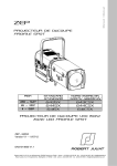
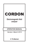
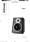
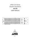
M•Flex 12
The M•Flex 12 is a full
range cabinet designed
around a co-axial 12” woofer
and 1” compression driver.
The co-axial design makes
the M•Flex 12 an ultra compact and lightweight speaker,
which can be used for a large
verity of applications.
Another advantage of the coaxial design is the uniform
dispersion pattern of 110 x
110 degrees, enabling the
M•Flex 12 to be flown horizontally or vertically.
Keyboard, CD and
microphone without
mixer
The coverage pattern also
allows the M•Flex 12 to be
flown in a line source configuration and it will therefore
work well in highly reverberant applications such as churches, airports or railway stations. When flown in a line
source array the output of the M•Flex 12 is very high and opens up for use in high
power applications such as live or large disco applications up to 300 people.
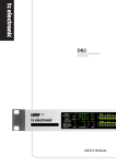
M•Flex 15
M•Flex 15 is the largest model in the M•Flex family and offers true full-range
sound reproduction with high SPL. It is aimed especially at top performance in live
venues, but applications also include AV productions, small-scale touring, fixed
installations and mobile DJ applications. M•Flex 15 can be mounted on a stand and
even used as a stage monitor. The integrated handles, lightweight design and sturdy
mechanical protection features allow you to handle M•Flex 15 with ease in all
applications.
6
Introduction
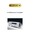
The 15” unit is a unique construction that features a lightweight chassis. The chassis is very open and
enables excellent coupling of the
diaphragm to the air in the cabinet.
It incorporates venting below the
spider to reduce power compression
and improve clarity. A special SoftRoll design is featured in the spider.
This design allows for more than +18mm excursion. A Kapton voice
coil former ensures excellent
mechanical stability. The 1” compression driver incorporated a very
lightweight diaphragm and with 107
dB sensitivity the unit is more efficient than many 2” drivers. But it
still has the advantage of a very
wide frequency response and runs
flat to 19 kHz. It is mounted behind
a 90 x 40 constant directivity horn
with excellent coverage control.
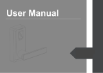
M•Flex as separate
microphone
monitor
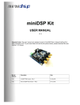
M•Fl ex S
For stronger reproduction of frequencies
M•Flex 15 connected
from 100 Hz and down, the M•Flex S is
via M•Flex S
designed to deliver the punchy kick from a
high-pass out
bass drum or a hard low-frequency bass line.
At the same time it contributes to an overall
increase of dynamics and sound pressure of
the M•Flex top-boxes. The 15” unit in
M•Flex S is a powerful construction that
features a lightweight chassis. The chassis is
very open and enables excellent coupling of
the diaphragm to the air in the cabinet. It
incorporates venting below the spider to
reduce power compression and improve
clarity. A special SoftRoll design is featured
in the spider. This design allows for more
than +-18mm excursion and extended sub
bass output. The 39 mm. voice coil former is
made of aluminium and ensures excellent
heat dissipation and very low power compression. A strong Kapton voice coil former
ensures excellent mechanical stability. Digitally powered the concept of a lightweight design in the entire M•Flex series is
maintained and an active crossover with hi-output link option ensures optimum
integration of M•Flex S with the rest of your M•Flex speakers.
Introduction
7
REAR PANEL INTERFACES
2
This section describes the rear panel interfaces.
POWER SECTION
P ow er i n pu t
The enclosed power cable features a Neutric PowerCon plug. The PowerCon plug is
locked into the socket thus eliminating the risk of accidentally having the main
power connector pulled out of the socket.
Note:
Remember to bring the cord at all times, as it is a custom
component often not yet found in normal electrical components.
Connect the power Plug in the power cord to an AC socket with a voltage, which
correspond to the amplifier current (110 or 220 volt depending on model – refer to
the M•Flex label on the rear panel).
P ow er s w i t ch
Before turning on the M•Flex speaker, make sure that all sources such as mixer,
musical instruments or CD players have been turned on, and the input gain controls
have been turned down.
When shutting down the system, reverse the process, i.e. turn off the speaker and
then all external sources.
LED indicator s
Blue
AC power on
Green
Receiving signal
Red
Limiter active
Note that on the front of the unit there is an additional:
• Blue LED that turns off when the unit is in standby waiting for a signal
• Red LED that indicates when the limiter is active
8
Rear panel interfaces
Note:
When the limiter LED comes on now and then, the speaker is
approaching the maximum output. The indicator comes on 2 dB
before limiting sets in, and occasional flickering of the LED is
fully normal. It does not mean that the speaker is overloaded.
However, pushing the volume up until the LED lights up almost
continuously might result in clipping the input and can in
extreme situations cause damage to the amplifier or drive units.
In this case, either reduce output level from the source, reduce
bass or treble boost on the EQ, or reduce master volume or
microphone gain.
See also “Stand-by function” on page 12.
INPUT SECTION
Micro ph on e i np ut
The microphone input accepts a standard XLR connector. Apart from accepting
microphones, the input can be switched to accept line signals by pressing the
Mic/line selector.
Mic./ li ne selector
Pressing the Mic/Line selector button enables the microphone input to be used as a
line input.
The Mic/line selector control the sensitivity of the input as follows:
• Mic.: +5 dB to +40 dB
• Line: PAD –20 dB to +15 dB
Signal Input Volume is controlled by the Mic. gain control.
Micro ph on e l in k
This XLR output enables you to link the microphone signal to other M•Flex speakers. It is a passive thru link so the output signal of the plug is similar to the input signal.
Li ne i np u t 1 & 2
Line 1 and 2 feature a ¼” Jack plug, which accepts a balanced or unbalanced line
level signal from sources such as CD players, cassette, MP3 players, computer
sound-card outputs, keyboard and other electrical instruments.
Note:
Input cables must be balanced. Unbalanced cables will reduce
the input level by 6 dB.
Rear panel interfaces
9
Volume control on these inputs is controlled by the Master volume control.
OUTPUT SECTION
Master volume
Adjusts the master output signal from - ∞ to 0 dB.
Mi x out
This output enables link of the mixed signal microphone/line signal to other M•Flex
boxes. Note that normally, a link output will only allow for a few boxes to be linked,
before the quality of the signal is reduced. In the M•Flex speakers, an active line
driver operates the link output, so an unlimited number of M•Flex speakers can be
linked while perfect signal quality is maintained.
B as s
Adjust the bass output of the speaker (Shelv - 100 Hz +- 10 dB)
T r e bl e
Adjust the high frequency output of the speaker (Shelv – 10 kHz +- 10 dB)
10
Rear panel interfaces
MOUNTING THE SPEAKERS
3
FLYING OPTIONS
The M•Flex models can be flown in three different ways:
• Use the custom designed U brackets. Typically used for flying horizontally in low
ceiling applications or on truss.
• Insert M6 eye bolts in the four flying points. Typically used when flying vertically.
• Insert the custom designed flying bracket in the four flying points. Typically used
for flying M•Flex in horizontal or vertical clusters
Caution:
Rigging should only be performed by professionals following
safe rigging standards and methods.
TRIPOD MOUNTING
Apart from the versatile flying options, the M•Flex 12 and M•Flex 15 also feature
an integrated 35mm aluminium top-hat adaptor, which enables the box to be placed
on a tripod. When using a tripod, note the following:
• Make sure that the tripod is capable of supporting the weight of the speaker (refer to
specifications in the back of this manual)
• Check that the tripod is placed on a stable surface
• Remember that tripod legs are trip hazards. Place them away from the audience or
place additional weight on the base of the stand to improve stability.
Mounting the speakers
11
STAND-BY FUNCTION
4
The active M•Flex models feature a stand-by function. When this function is
enabled and no input signal has been sensed for one hour (or the signal is at a very
low level), the amplifier automatically shuts down. When signal is restored to the
speaker, the amplifier will automatically be turned on.
The stand-by function is disabled by default in models after and including:
•
•
•
•
M•Flex 12 (115 volt) models - serial number 701124
M•Flex 12 (230 volt) models - serial number 701316
M•Flex 15 (115 volt) models - serial number 701555
M•Flex 15 (230 volt) models - serial number 701694
Note that the serial number label can be found on the back of the speaker unit. The
stand-by function is enabled by default in all models with serial numbers prior to
these.
ENABLING OR DISABLING THE STANDBY FUNCTION
The stand-by function is enabled by removing a jumper from a printed circuit board
(PCB) inside the fixture.
To access the PCB:
1 Using a Torx 20 screwdriver, remove the 8 screws that hold the woofer cover in place.
12
Stand-by function
2 Remove the woofer cover.
3 Using a Phillips screwdriver, remove the woofer from the speaker casing.
4 Once you remove the woofer you will be able to see the PCB inside the fixture casing.
Stand-by function
13
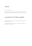
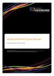
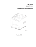
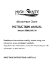
5 The jumper is located at the lower-right corner of the PCB. To enable the stand-by
function remove the jumper at position JP1 (if present). To disable the stand-by
function add a jumper (P/N 05120701).
PL1
F1
PL11
C9
PL3
01301002D
PL2
L1
1
C18
SW1
C10
C17
PL10
RL1
T1
C19
D2
R15
+
R25
R20
Q3
IC3
+
D3
C12
-
R12
C3
R9
+
+ C8
R14
D4
D5
Q1
R17
R11
R8
Q2
R7
R6
R5
R24
R1
R2
C13
R4
C15
C16 R3
R23
Jumper
C14
C6
C7
PL5
R16
JP1
R18
~
IC1
C5
IC2
PL9
R13 C2
D1
C11
R21
PL8
R19
Q4
+
C1
C4
PL7
R10
R22
+
PL6
6 Replace the woofer and the woofer cover before applying power to the unit.
14
Stand-by function
5
SERVICE
Refer all service, other than that described here, to qualified service personnel.
CARE AND MAINTENANCE
The M•Flex speakers have been designed for mobile use and will - when used with
common sense care - provide flawless performance for many years. However, we
recommend that the following points are noted:
• If the speakers have been subjected to very low temperatures, it is advisable to allow
for a one hour warm up period before operating them at full output. This to avoid
the risk of short-circuiting the amplifier and processor PCB due to condense water.
• The M•Flex cabinets can be used in short-term out-door applications, but have not
been designed for long-term outdoor installations.
• Clean the cabinets with a general-purpose household detergent. Grease or marking
tape residue can be removed with alcohol or mineral spirits.
• Protective speaker covers are available for the M•Flex models and we strongly recommend these if the speakers are frequently transported.
Service
15
T ROUBLESHOOTING
A
Problem
Remedy
No sound.
Make sure that all XLR cables are wired according to the
AES standards:
Hot (+) - Pin2
Cold (-) - Pin3
Shield (ground) - Pin1
Make sure that the signal is strong enough. A weak signal
may result in the unit shutting down if the stand-by function
is enabled.
No sound when microphone is
connected to mic. input.
The microphone requires phantom power. Switch to a
dynamic microphone.
Distorted sound, but peak indicator
does not come on.
Mixer or other sources is overdriven/clipping. Turn down the
signal from the source.
Low input signal.
Ensure that the input cables are balanced.
Feedback when microphone is turned
up.
Microphones have very different characteristics depending
on which application they are designed for. Make sure that
the microphone is a vocal microphone with a Cardioid
(unidirectional) characteristic. Shure offer good help to
choosing the right microphone. Check:
http://www.shure.com/microphones/microphone_help.asp
Turn Microphone away from the speaker.
Reduce bass and treble EQ
Table 1: Troubleshooting
16
Troubleshooting
B
S PECIFICATIONS
M•Fl ex 12 Sp e ci fic a ti on s
SYSTEM PERFORMANCE
Max long term SPL (calculated) . . . . . . . . . . . . . . . . . . . . . . . . . . . . . . . . . . . . . . . . . 122 dB
Max peak SPL (calculated) . . . . . . . . . . . . . . . . . . . . . . . . . . . . . . . . . . . . . . . . . . . . . 128 dB
Frequency range +/- 10dB . . . . . . . . . . . . . . . . . . . . . . . . . . . . . . . . . . . . . . . 69 Hz - 20 kHz
Dispersion (-6 dB) . . . . . . . . . . . . . . . . . . . . . . . . . . . . . . . . . . . . . . . . . . . 110 x 110 degrees
Auto stand-by . . . . . . . . . . . . . . . . . . . . . . . . . . . . . . . . . . . . . . . . . . . . . . . . . . . . . . . 12 min
Mix output impedance . . . . . . . . . . . . . . . . . . . . . . . . . . . . . . . . . . . . . . . . . . . . . . . . .40 ohm
LF EQ, Shelving . . . . . . . . . . . . . . . . . . . . . . . . . . . . . . . . . . . . . . . . . . . +/-10 dB @ 100 Hz
HF EQ, Shelving . . . . . . . . . . . . . . . . . . . . . . . . . . . . . . . . . . . . . . . . . . . +/-10 dB @ 10 kHz
HF TRANSDUCER
Type . . . . . . . . . . . . . . . . . . . . . . . . . . . . . . . . . . 1” compression driver with 1.4” diaphragm
Power rating, IEC 268 . . . . . . . . . . . . . . . . . . . . . . . . . . . . . . . . . . . . . . . . . . . . . . . . . . 50 W
Power rating, peak . . . . . . . . . . . . . . . . . . . . . . . . . . . . . . . . . . . . . . . . . . . . . . . . . . . . 200 W
Sensitivity . . . . . . . . . . . . . . . . . . . . . . . . . . . . . . . . . . . . . . . . . . . . . . . . . . . . . . . . . . 105 dB
LF TRANSDUCER
Type . . . . . . . . . . . . . . . . . . . . . . . . . . . . . . . . . . . . . . . . . . . . . 12” coaxial with 2” voice coil
Power rating, IEC 268 . . . . . . . . . . . . . . . . . . . . . . . . . . . . . . . . . . . . . . . . . . . . . . . . . 250 W
Power rating, peak . . . . . . . . . . . . . . . . . . . . . . . . . . . . . . . . . . . . . . . . . . . . . . . . . . . 1000 W
Sensitivity . . . . . . . . . . . . . . . . . . . . . . . . . . . . . . . . . . . . . . . . . . . . . . . . . . . . . . . . . . . 98 dB
AMPLIFIER
LF output, continuous RMS . . . . . . . . . . . . . . . . . . . . . . . . . . . . . . . . . . . . . . . . . . . . 350 W
HF output, continuous RMS . . . . . . . . . . . . . . . . . . . . . . . . . . . . . . . . . . . . . . . . . . . . . 70 W
LINE INPUT
Type . . . . . . . . . . . . . . . . . . . . . . . . . . . . . . . . . . . . . . . . . . . . . . . . . . . . . . . . . . . . . Balanced
Impedance . . . . . . . . . . . . . . . . . . . . . . . . . . . . . . . . . . . . . . . . . . . . . . . . . . . . . . . . 27 K ohm
Line 1 & 2 sensitivity . . . . . . . . . . . . . . . . . . . . . . . . . . . . . . . . . . . . . . . . . . . . . .- ∞ to 0 dB
MICROPHONE INPUT
Type . . . . . . . . . . . . . . . . . . . . . . . . . . . . . . . . . . . . . . . . . . . . . . . . . . . . . . . . . . . . . Balanced
Impedance, pad on. . . . . . . . . . . . . . . . . . . . . . . . . . . . . . . . . . . . . . . . . . . . . . . . . 3.5 K ohm
Impedance, pad off . . . . . . . . . . . . . . . . . . . . . . . . . . . . . . . . . . . . . . . . . . . . . . . . . . 4 K ohm
Input sensitivity, pad on. . . . . . . . . . . . . . . . . . . . . . . . . . . . . . . . . . . . . . . . . . .-21 to +14 dB
Input sensitivity, pad off . . . . . . . . . . . . . . . . . . . . . . . . . . . . . . . . . . . . . . . . . . +5 to +40 dB
Specifications
17
ELECTRICAL
AC input, US model . . . . . . . . . . . . . . . . . . . . . . . . . . . . . . . . . . . . . . . . . . . . . . 110 V, 60 Hz
AC input, EU model . . . . . . . . . . . . . . . . . . . . . . . . . . . . . . . . . . . . . . . . . . . . . . 230 V, 50 Hz
Power consumption, peak. . . . . . . . . . . . . . . . . . . . . . . . . . . . . . . . . . . . . . . . . . . . . . . 420 W
Power consumption, average . . . . . . . . . . . . . . . . . . . . . . . . . . . . . . . . . . . . . . . . . . . . 145 W
Power consumption, no signal . . . . . . . . . . . . . . . . . . . . . . . . . . . . . . . . . . . . . . . . . . . . 53 W
Power consumption, standby . . . . . . . . . . . . . . . . . . . . . . . . . . . . . . . . . . . . . . . . . . . . . . 5 W
Maximum current consumption . . . . . . . . . . . . . . . . . . . . 2.23 A @ 230 V, 4.46 A @ 115 V
PHYSICAL
Dimensions. . . . . . . . . . . . . . . . . . . . . . . . . . . . . . . 50 x 39 x 32 cm (19.7 x 15.4 x 12.6 in.)
Weight. . . . . . . . . . . . . . . . . . . . . . . . . . . . . . . . . . . . . . . . . . . . . . . . . . . . . . . . 15 kg (33 lbs)
Flying attachment: . . . . . . . . . . . . . . . . . . . . . . . . . . . . . 4 points for M6 threaded hardware
ACCESSORIES
Speaker cover
Flying bracket for cluster and array configuration
M•Flex 15 Specifications
SYSTEM PERFORMANCE
Max long term SPL (calculated) . . . . . . . . . . . . . . . . . . . . . . . . . . . . . . . . . . . . . . . . 126 dB
Max peak SPL (calculated) . . . . . . . . . . . . . . . . . . . . . . . . . . . . . . . . . . . . . . . . . . . . 132 dB
Frequency range +/- 10dB . . . . . . . . . . . . . . . . . . . . . . . . . . . . . . . . . . . . . . . 49 Hz - 20 kHz
Dispersion (-6 dB) . . . . . . . . . . . . . . . . . . . . . . . . . . . . . . . . . . . . . . . . . . . . . 90 x 40 degrees
Auto stand-by . . . . . . . . . . . . . . . . . . . . . . . . . . . . . . . . . . . . . . . . . . . . . . . . . . . . . . . . 12 min
Mix output impedance . . . . . . . . . . . . . . . . . . . . . . . . . . . . . . . . . . . . . . . . . . . . . . . . 40 ohm
LF EQ, Shelving. . . . . . . . . . . . . . . . . . . . . . . . . . . . . . . . . . . . . . . . . . . +/-10 dB @ 100 Hz
HF EQ, Shelving . . . . . . . . . . . . . . . . . . . . . . . . . . . . . . . . . . . . . . . . . . +/-10 dB @ 10 kHz
HF TRANSDUCER
Type . . . . . . . . . . . . . . . . . . . . . . . . . . . . . . . . 1” compression driver with 1 3/4” diaphragm
Power rating, IEC 268 . . . . . . . . . . . . . . . . . . . . . . . . . . . . . . . . . . . . . . . . . . . . . . . . . . 60 W
Power rating, peak . . . . . . . . . . . . . . . . . . . . . . . . . . . . . . . . . . . . . . . . . . . . . . . . . . . . 240 W
Sensitivity . . . . . . . . . . . . . . . . . . . . . . . . . . . . . . . . . . . . . . . . . . . . . . . . . . . . . . . . . . 107 dB
LF TRANSDUCER
Type . . . . . . . . . . . . . . . . . . . . . . . . . . . . . . . . . . . . . . . . . . . . .15” woofer with 3” voice coil
Power rating, IEC 268 . . . . . . . . . . . . . . . . . . . . . . . . . . . . . . . . . . . . . . . . . . . . . . . . . 320 W
Power rating, peak . . . . . . . . . . . . . . . . . . . . . . . . . . . . . . . . . . . . . . . . . . . . . . . . . . . 1280 W
Sensitivity . . . . . . . . . . . . . . . . . . . . . . . . . . . . . . . . . . . . . . . . . . . . . . . . . . . . . . . . . . 101 dB
AMPLIFIER
LF output, continuous RMS . . . . . . . . . . . . . . . . . . . . . . . . . . . . . . . . . . . . . . . . . . . . . 350 W
HF output, continuous RMS. . . . . . . . . . . . . . . . . . . . . . . . . . . . . . . . . . . . . . . . . . . . . . 70 W
LINE INPUT
Type . . . . . . . . . . . . . . . . . . . . . . . . . . . . . . . . . . . . . . . . . . . . . . . . . . . . . . . . . . . . . Balanced
Impedance . . . . . . . . . . . . . . . . . . . . . . . . . . . . . . . . . . . . . . . . . . . . . . . . . . . . . . . 27 K ohm
Line 1 & 2 sensitivity . . . . . . . . . . . . . . . . . . . . . . . . . . . . . . . . . . . . . . . . . . . . . . . - • to 0 dB
18
Specifications
MICROPHONE INPUT
Type . . . . . . . . . . . . . . . . . . . . . . . . . . . . . . . . . . . . . . . . . . . . . . . . . . . . . . . . . . . . . Balanced
Impedance, pad on. . . . . . . . . . . . . . . . . . . . . . . . . . . . . . . . . . . . . . . . . . . . . . . . . 3.5 K ohm
Impedance, pad off . . . . . . . . . . . . . . . . . . . . . . . . . . . . . . . . . . . . . . . . . . . . . . . . . . 4 K ohm
Input sensitivity, pad on. . . . . . . . . . . . . . . . . . . . . . . . . . . . . . . . . . . . . . . . . . .-21 to +14 dB
Input sensitivity, pad off . . . . . . . . . . . . . . . . . . . . . . . . . . . . . . . . . . . . . . . . . . +5 to +40 dB
ELECTRICAL
AC input, US model . . . . . . . . . . . . . . . . . . . . . . . . . . . . . . . . . . . . . . . . . . . . . 110 V, 60 Hz
AC input, EU model . . . . . . . . . . . . . . . . . . . . . . . . . . . . . . . . . . . . . . . . . . . . . 230 V, 50 Hz
Power consumption, peak . . . . . . . . . . . . . . . . . . . . . . . . . . . . . . . . . . . . . . . . . . . . . . 510 W
Power consumption, average . . . . . . . . . . . . . . . . . . . . . . . . . . . . . . . . . . . . . . . . . . . . 185 W
Power consumption, no signal. . . . . . . . . . . . . . . . . . . . . . . . . . . . . . . . . . . . . . . . . . . . 53 W
Power consumption, standby . . . . . . . . . . . . . . . . . . . . . . . . . . . . . . . . . . . . . . . . . . . . . . 5 W
Maximum current consumption . . . . . . . . . . . . . . . . . . . .2.23 A @ 230 V, 4.46 A @ 115 V
PHYSICAL
Dimensions . . . . . . . . . . . . . . . . . . . . . . . . . . . . . . . . . . . 67 x 48 x 40 cm (26 x 19 x 16 in.)
Weight . . . . . . . . . . . . . . . . . . . . . . . . . . . . . . . . . . . . . . . . . . . . . . . . . . . . . . . .25 kg (55 lbs)
Flying attachment . . . . . . . . . . . . . . . . . . . . . . . . . . . . . . 4 points for M6 threaded hardware
ACCESSORIES
Speaker cover
Flying bracket for cluster and array configuration
M•Fl ex Sub Specifications
SYSTEM PERFORMANCE
Max long term SPL (calculated) . . . . . . . . . . . . . . . . . . . . . . . . . . . . . . . . . . . . . . . . . 123 dB
Max peak SPL (calculated) . . . . . . . . . . . . . . . . . . . . . . . . . . . . . . . . . . . . . . . . . . . . . 129 dB
Frequency range +/- 10dB . . . . . . . . . . . . . . . . . . . . . . . . . . . . . . . . . . . . . . . . . . 45 - 250 Hz
Auto stand-by . . . . . . . . . . . . . . . . . . . . . . . . . . . . . . . . . . . . . . . . . . . . . . . . . . . . . . . .1 hour
TRANSDUCER
Type . . . . . . . . . . . . . . . . . . . . . . . . . . . . . . . . . . . . . . . . . . . . . 15” woofer with 3” voice coil
Power rating, IEC 268 . . . . . . . . . . . . . . . . . . . . . . . . . . . . . . . . . . . . . . . . . . . . . . . . . 320 W
Power rating, peak . . . . . . . . . . . . . . . . . . . . . . . . . . . . . . . . . . . . . . . . . . . . . . . . . . . 1280 W
Sensitivity . . . . . . . . . . . . . . . . . . . . . . . . . . . . . . . . . . . . . . . . . . . . . . . . . . . . . . . . . . . 97 dB
AMPLIFIER
LF output, continuous RMS . . . . . . . . . . . . . . . . . . . . . . . . . . . . . . . . . . . . . . . . . . . . 350 W
High pass filter. . . . . . . . . . . . . . . . . . . . . . . . . . . . . . . . . . . . . . . . . . . . . . 115 Hz, 24 dB LR
LINE INPUT
Type . . . . . . . . . . . . . . . . . . . . . . . . . . . . . . . . . . . . . . . . . . . . . . . . . . . . . . . . . . . . . Balanced
Impedance . . . . . . . . . . . . . . . . . . . . . . . . . . . . . . . . . . . . . . . . . . . . . . . . . . . . . . . . 22 K ohm
Specifications
19
ELECTRICAL
AC input, US model . . . . . . . . . . . . . . . . . . . . . . . . . . . . . . . . . . . . . . . . . . . . . . 110 V, 60 Hz
AC input, EU model . . . . . . . . . . . . . . . . . . . . . . . . . . . . . . . . . . . . . . . . . . . . . . 230 V, 50 Hz
Power consumption, peak. . . . . . . . . . . . . . . . . . . . . . . . . . . . . . . . . . . . . . . . . . . . . . . 510 W
Power consumption, average . . . . . . . . . . . . . . . . . . . . . . . . . . . . . . . . . . . . . . . . . . . . 185 W
Power consumption, no signal . . . . . . . . . . . . . . . . . . . . . . . . . . . . . . . . . . . . . . . . . . . . 53 W
Power consumption, standby . . . . . . . . . . . . . . . . . . . . . . . . . . . . . . . . . . . . . . . . . . . . . . 5 W
Maximum current consumption . . . . . . . . . . . . . . . . . . . . 2.23 A @ 230 V, 4.46 A @ 115 V
PHYSICAL
Dimensions. . . . . . . . . . . . . . . . . . . . . . . . . . . . . . . . . . . . 67 x 48 x 40 cm (26 x 19 x 16 in.)
ACCESSORIES
Speaker cover
Flying bracket for cluster and array configuration
20
Specifications
TC E LECTRONIC S OFTWARE
L ICENSE A GREEMENT
C
Software Package for the M•Flex 12/15/sub, hereafter referred to as the ‘Product’.
PLEASE READ THIS LICENSE CAREFULLY BEFORE USING THE SOFTWARE IN THE
‘PRODUCT’. BY PROCEEDING AND USING THE SOFTWARE, YOU ARE AGREEING TO BE
BOUND BY THE TERMS OF THIS LICENSE. IF YOU DO NOT AGREE TO THE TERMS OF THIS
LICENSE, PROMPTLY RETURN THE UNUSED PRODUCT TO THE PLACE WHERE YOU
OBTAINED IT AND YOUR MONEY WILL BE REFUNDED.
1. License.
TC Electronic grants to you the right to use this copy of TC Electronic software and the related
documentation (the "Software") in the 'Product'. You own the media on which the Software is recorded, but
TC Electronic retains title to the Software and related documentation including copies, regardless of form or
media, and to all copyrights therein. You may not reproduce the Software or the media holding the copy
protection ("Authorization") in any shape or form.
2. Transfer of Rights.
You may transfer all your license rights in the Software, the related documentation and a copy of this
License to another party, provided the other party reads and agrees to accept the terms and conditions of this
license.
3. Restrictions.
The Software contains copyrighted material, trade secrets and other proprietary material of TC Electronic
and/or its partners. In order to protect this, and except as permitted by applicable legislation, you may not
de-compile, reverse engineer, disassemble, copy, decode or otherwise reduce the Software to a human
perceivable form. You may not modify, adapt, network, rent, lease, loan, distribute or create derivative
works based upon the Software in whole or in part. You may not electronically transmit the Software from
the Product platform to another in a network. You may not separate the Software, in its entirety or in parts,
from the hardware of the Product.
4. Termination.
This License is effective until terminated. You may terminate this License at any time by selling the
'Product'. This License will terminate immediately without notice from TC Electronic, if you fail to comply
with any provision of this License.
5. Disclaimer of Warranty on TC Electronic Software.
You expressly acknowledge and agree that use of the Software is at your sole risk. The Software and related
documentation are provided on an "AS IS" basis and without warranty of any kind. TC Electronic and TC
Electronic' Licensee(s) (for the purposes of provisions 5 and 6, TC Electronic and TC Electronic'
Licensee(s) shall be collectively referred to as "TC Electronic")
EXPRESSLY DISCLAIM ALL WARRANTIES, EXPRESS OR IMPLIED, INCLUDING BUT NOT
LIMITED TO, THE IMPLIED WARRANTIES OF MERCHANTABILITY AND FITNESS FOR A
PARTICULAR PURPOSE.
TC ELECTRONIC DOES NOT WARRANT THAT THE FUNCTIONS CONTAINED IN THE
SOFTWARE WILL MEET YOUR REQUIREMENTS, OR THAT THE OPERATION OF THE
TC Electronic Software License Agreement
21
SOFTWARE WILL BE UNINTERRUPTED OR ERROR-FREE, OR THAT DEFECTS IN THE
SOFTWARE WILL BE CORRECTED.
FURTHERMORE, TC ELECTRONIC DOES NOT WARRANT OR MAKE ANY REPRESENTATIONS
REGARDING THE USE OR THE RESULTS OF THE USE OF THE SOFTWARE OR RELATED
DOCUMENTATION IN TERMS OF THEIR CORRECTNESS, ACCURACY, RELIABILITY, OR
OTHERWISE.
NO ORAL OR WRITTEN INFORMATION OR ADVICE GIVEN BY TC ELECTRONIC OR AN TC
ELECTRONIC AUTHORIZED REPRESENTATIVE SHALL CREATE A WARRANTY OR IN ANY
WAY INCREASE THE SCOPE OF THIS WARRANTY. SHOULD THE SOFTWARE PROVE
DEFECTIVE, YOU (AND NOT TC ELECTRONIC OR A TC ELECTRONIC AUTHORIZED
REPRESENTATIVE) ASSUME THE JURISDICTIONS.
SOME STATES DO NOT ALLOW THE EXCLUSION OF IMPLIED WARRANTIES, SO THE ABOVE
EXCLUSION MAY NOT APPLY TO YOU.
6. Limitation of Liability.
UNDER NO CIRCUMSTANCES INCLUDING NEGLIGENCE, SHALL TC ELECTRONIC BE LIABLE
FOR ANY INCIDENTAL SPECIAL OR CONSEQUENTIAL DAMAGES THAT RESULT FROM THE
USE OR INABILITY TO USE THE SOFTWARE OR RELATED DOCUMENTATION, EVEN IF TC
ELECTRONIC OR A TC ELECTRONIC AUTHORIZED REPRESENTATIVE HAS BEEN ADVISED
OF THE POSSIBILITY OF SUCH DAMAGES. SOME JURISDICTIONS DO NOT ALLOW THE
LIMITATION OR EXCLUSION OF
LIABILITY FOR INCIDENTAL OR CONSEQUENTIAL DAMAGES SO THE ABOVE LIMITATION
OR EXCLUSION MAY NOT APPLY TO YOU.
In no event shall TC Electronic's total liability to you for all damages, losses, and causes of action (whether
in contract, tort (including negligence) or otherwise) exceed the amount paid by you for the Software.
7. Governing Law and Severability.
This License shall be governed by and construed in accordance with the laws of Denmark, as applied to
agreements entered into and to be performed entirely within Denmark between Danish residents. If for any
reason a court of competent jurisdiction finds any provision of this License, or portion
thereof, to be unenforceable, that provision of the License shall be enforced to the maximum extent
permissible so as to effect the intent of the parties, and the remainder of this License shall continue in full
force and effect.
8. Complete Agreement.
This License constitutes the entire agreement between the parties with respect to the use of the Software and
the related documentation and supersedes all prior contemporaneous understandings or agreements, written
or oral, regarding such subject matter. No amendment to or modification of this License will be binding
unless in writing and signed by a duly authorized representative of TC Electronic.
If you have any questions concerning this Agreement or TC Electronic, please write to:
TC ELECTRONIC, Sindalsvej 34, 8240 Risskov, Denmark.
E-mail: [email protected]
22
TC Electronic Software License Agreement
TC Electronic Software License Agreement
23
URL: http://www.mach-audio.com