1
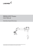
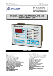
R PRIMA ENT/DNT User MANUAL Operating Surgical Microscopy To ensure proper use of this instrument as well as to avoid injury while operating instrument, understanding this manual completely before use is highly recommended. 6137000-795PRIMA ENT/DNTIssue 1.3 Printed on Apr, 2015 Prima ENT/DNT Prima ENT/DNT is a trade name for LABOMED Products. LABOMED is a registered trademark of Labo America, Inc. All other trademarks are the property of their respective owners. The information contained in this document was accurate at the time of publication. Specifications are subject to change without notice. LABOMED reserves the right to make changes to the product described in this user manual without notice and without incorporating those changes in any products already sold. ISO 9001/13485 Certified – LABOMED products are designed and manufactured under quality processes that meet ISO 9001/13485 requirements. No part of this publication may be reproduced, stored in a retrieval system, or transmitted in any form or by any means: electronic, mechanical, recording, or otherwise, without the prior written permission from LABOMED. 2 Prima ENT/DNT List Of Contents 1. Introduction and Intended Use 4 2. Product Description 5-6 3. Warnings and Cautions 7-8 4. Explanation of Symbols 9 5. Standards and Directives 10 6. Unpacking11 7. Installation Instructions - 7A Installation of Base (Mobile Stand) 12-13 - 7B Microscope Installation14-15 8. Electrical Connections - Replacing the Illumination Source16 - Replacing the Fuse 16 - Data Plate Details 16 9. Control Elements 17 10. Using the Microscope18-19 11. Changing the Objectives and Eyepieces 20 12. Use of Accessories21-22 13. Thermal Cut-Off23 14. Tension Adjustment 23 15. Moving the Instrument 24 16. Care and Maintenance 25-26 17. Ambient Requirements 27 18. Disposal 28 19. Troubleshooting Table 29-30 20. Technical Specifications 31 21. Guidance Tables 32-35 22. Dimensions and Weight36 23. Glossary 37 24. Warranty 38 3 1 INTRODUCTION AND INTENDED USE Prima ENT/DNT LABOMED Prima ENT/DNT is a surgical and diagnostic microscope that is adaptable for different surgical needs for consistent visualization during all intraoperative phases of ENT and dentistry surgeries by providing a magnified view of the surgical field without compromising performance. The microscope provides extremely high optical image quality, good depth of focus, and a wide field of view for precise surgery.Illumination control and high eye point of the observation head helps reduce the user’s work fatigue and allows comfortable use over a long period. Salient features of this microscope are: 1. The observation head can easily be positioned with the help of a suspension arm. 2. An advanced 5-step magnification changer allows optimal magnification for various needs at five different magnification levels. 3. Cold light illumination with a high-intensity 50W LED lamp is provided using a fiber optic guide for proper illumination. Illumination can be adjusted using the intensity control knob conveniently located at the suspension arm and easily accessible to the user. 4. When the microscope is not in use, the suspension arm can be folded over the main body for compact storage. 5. The rigid H-shape base with caster wheels provides the instrument with stability and mobility. Intended Use The Prima ENT/DNT microscope is an AC powered device intended for use during diagnosis and surgery to provide a magnified view of the region of interest. NOTE: Use Prima ENT/DNT microscopes as specified in the intended use. Configurations Microscope Catalogue no. Prima ENT6137000-000 Prima DNT6138000-000 4 Prima ENT/DNT 2 PRODUCT DESCRIPTION Prima DNT 4 13 7 5 11 23 19 22 21 6 12 8 25 10 9 14 24 18 15 3 16 17 20 1 1. 2. 3. 4. 5. 6. 7. 8. 9. 10. 11. 12. 13. Wheel with brake 14. Ergo Head 0-210° adjustable H shape metal base 15. Magnification changer (magnichanger) Column 16.Handles Swivel arm 17. Common main objective (CMO) Suspension arm 18. Magnichanger inclination Swivel arm locking knob movement lock Suspension arm movement locking knob 19. Illumination control knob Coupling movement locking knob 20. Fine focusing knob Inclined coupling 21. iVu Camera inlet Inclined coupling movement knob 22. On/Off switch Suspension arm hydraulic movement lock 23. Power inlet Suspension arm spring tension adjustment24. Eyepieces Swivel arm covers 25. Counter balancing knob 5 Prima ENT/DNT Prima ENT 4 13 7 11 5 24 19 23 6 12 22 9 8 26 10 25 14 18 15 16 3 17 21 2 20 1 1. 2. 3. 4. 5. 6. 7. 8. 9. 10. 11. 12. 13. 6 Wheel with brake 14. Binocular head H shape base 15. Magnification changer Column 16.Handles Swivel arm 17. Common main objective (CMO) Suspension arm 18. Magnichanger inclination movement lock Swivel arm locking knob 19. Illumination control knob Suspension arm movement locking knob 20. Foot pedal for Z-axis (optional) Coupling movement locking knob 21. Fine focusing knob Inclined coupling 22. iVu Camera inlet Inclined coupling movement knob 23. On/Off switch Suspension arm hydraulic movement lock 24. Power inlet Suspension arm spring tension adjustment25. Eyepieces Swivel arm covers 26. Counter balancing knob 3 WARNINGS AND CAUTIONS Prima ENT/DNT LABOMED is not responsible for the safety and reliability of this instrument when: - Assembly, disassembly, repair, or modification is made by unauthorized dealers or persons. - The instrument is not used in accordance with this user manual. A WARNING is an instruction that draws attention to the risk of injury or death. WARNING:USERS OF THIS EQUIPMENT SHOULD BE THOROUGHLY TRAINED IN THE APPROPRIATE MEDICAL PROCEDURES. FURTHERMORE, THEY SHOULD TAKE THE TIME TO READ AND UNDERSTAND THESE INSTRUCTIONS BEFORE PERFORMING ANY PROCEDURE. THEY SHOULD ALSO READ AND UNDERSTAND THE INSTRUCTIONS FOR ANY OTHER EQUIPMENT USED IN CONJUNCTION WITH THIS MICROSCOPE (i.e. ELECTROSURGICAL GENERATORS). FAILURE TO DO SO MAY RESULT IN INJURY TO THE PATIENT AND/OR DAMAGE TO THE MICROSCOPE. WARNING:THIS INSTRUMENT SHOULD BE USED IN STRICT ACCORDANCE WITH THE INSTRUCTIONS OUTLINED IN THIS USER MANUAL. THE SAFETY OF THE OPERATOR AND THE PERFORMANCE OF THE INSTRUMENT CANNOT BE GUARANTEED IF USED IN A MANNER NOT SPECIFIED BY LABOMED. WARNING:DO NOT REPAIR OR SERVICE THIS INSTRUMENT WITHOUT AUTHORIZATION FROM THE MANUFACTURER. ANY REPAIR OR SERVICE TO THIS INSTRUMENT MUST BE PERFORMED BY EXPERIENCED PERSONNEL OR DEALERS WHO ARE TRAINED BY LABOMED, OR SERIOUS INJURY TO THE OPERATOR OR PATIENT MAY OCCUR. WARNING:MODIFICATIONS TO THIS INSTRUMENT ARE NOT ALLOWED. ANY MODIFICATION TO THIS UNIT MUST BE AUTHORIZED BY LABOMED, OR SERIOUS INJURY TO THE OPERATOR OR PATIENT MAY OCCUR. WARNING:IF THIS INSTRUMENT IS MODIFIED, APPROPRIATE INSPECTION AND TESTING MUST BE CONDUCTED TO ENSURE CONTINUED SAFE USE OF THIS INSTRUMENT. WARNING:TO AVOID RISK OF ELECTRIC SHOCK, THIS EQUIPMENT MUST ONLY BE CONNECTED TO A SUPPLY MAIN WITH PROPER EARTHING, OR DAMAGE TO THIS INSTRUMENT AND/OR INJURY TO THE OPERATOR OR PATIENT MAY OCCUR. WARNING:ENSURE THAT THE VOLTAGE APPLIED TO THE UNIT IS THE SAME AS THE VOLTAGE INDICATED ON THE DATA PLATE, OR DAMAGE TO THE UNIT MAY OCCUR. WARNING:THIS INSTRUMENT MUST BE PLUGGED IN TO AN OUTLET WITH AN EARTH GROUND. DO NOT REMOVE OR DAMAGE THE EARTH GROUND CONNECTION ON THE POWER INPUT CONNECTOR OR THE UNIT’S POWER CORD, OR DAMAGE TO THE INSTRUMENT AND/OR INJURY TO THE OPERATOR OR PATIENT MAY OCCUR. WARNING:THE EQUIPMENT OR SYSTEM SHOULD NOT BE USED ADJACENT OR STACKED WITH OTHER EQUIPMENT LIKE MRI MACHINES, RFID, SECURITY SYSTEMS LIKE METAL DETECTORS, OR SIMILAR DEVICES. IF ADJACENT OR STACKED USE IS NECESSARY, THE EQUIPMENT OR SYSTEM SHOULD BE OBSERVED TO VERIFY NORMAL OPERATION IN THE CONFIGURATION IN WHICH IT WILL BE USED. 7 Prima ENT/DNT WARNING:THIS INSTRUMENT IS NOT SUITABLE FOR USE IN THE PRESENCE OF FLAMMABLE ANESTHETIC MIXTURES SUCH AS OXYGEN OR NITROUS OXIDE. WARNING:LED RADIATION - DO NOT STARE DIRECTLY INTO THE BEAM WHEN THE MICROSCOPE IS IN THE ON POSITION. WARNING:THE USE OF ACCESSORIES OR CABLES OTHER THAN THOSE SPECIFIED, WITH THE EXCEPTION OF THOSE SOLD BY THE MANUFACTURER AS REPLACEMENT PARTS FOR THE INTERNAL COMPONENTS, MAY RESULT IN INCREASED EMISSIONS OR DECREASED IMMUNITY OF THE EQUIPMENT OR SYSTEM. A CAUTION is an instruction that draws attention to the risk of damage to the product. CAUTION: THE INTERNAL CIRCUITRY OF THE INSTRUMENT CONTAINS ELECTROSTATIC SENSITIVE DEVICES (ESD) THAT MAY BE SENSITIVE TO STATIC CHARGES PRODUCED BY THE HUMAN BODY. DO NOT REMOVE THE COVERS WITHOUT TAKING PROPER ESD PRECAUTIONS. CAUTION: DO NOT USE SOLVENTS OR STRONG CLEANING SOLUTIONS ON ANY PART OF THIS INSTRUMENT, AS DAMAGE TO THE UNIT MAY OCCUR. SEE THE CARE AND MAINTENANCE SECTION FOR DETAILED CLEANING INSTRUCTIONS. CAUTION: MEDICAL ELECTRONIC EQUIPMENT NEEDS SPECIAL PRECAUTIONS WITH RESPECT TO ELECTROMAGNETIC CHARGE (EMC) AND NEEDS TO BE INSTALLED AND SERVICED ACCORDING TO THE EMC INFORMATION PROVIDED IN THE ACCOMPANYING DOCUMENTS. CAUTION: PORTABLE AND MOBILE RF COMMUNICATIONS EQUIPMENT CAN AFFECT MEDICAL ELECTRICAL EQUIPMENT. CAUTION: THIS INSTRUMENT IS NOT TO BE USED NEAR HIGH-FREQUENCY EMITTING SURGICAL EQUIPMENT. CAUTION: DO NOT CONNECT ANY EQUIPMENT TO THE DEVICE OTHER THAN THOSE INTENDED FOR USE WITH THE DEVICE. CAUTION: DO NOT USE A CONVERTER ADAPTER THAT WILL CONVERT THE THREE-PRONG AC PLUG TO A TWO-PRONG LINE PLUG. THE POWER SUPPLY IN THIS MICROSCOPE WILL NOT BE PROPERLY GROUNDED, AND ELECTRIC SHOCK MAY RESULT. CAUTION: REMOVE THE AC POWER PLUG FROM THE WALL SOCKET WHILE CHECKING FOR A BLOWN FUSE. CAUTION: DO NOT ROLL THE MICROSCOPE OVER CABLES OR HOSES. CAUTION: DO NOT REMOVE FERRITE BEADS IF APPLIED TO CABLES. 8 4 EXPLANATION OF SYMBOLS Prima ENT/DNT Caution: Observe all warning labels and notes! If any label is missing on your instrument or has become illegible, please contact the manufacturer to obtain new labels. Brightness control: After the illumination has been switched on, the user can continuously adjust brightness by turning the appropriate knob. Accompanying documents must be consulted. Compliance to medical device directive 93/42/EEC. Protective earthing This way up - indicates the correct upright position of the transport package. Keep dry - the transport package shall be kept away from rain. Year of manufacture used on product data plate. Fragile - contents of the transport package are fragile and should be handled with care. Electromagnetic interference can occur in the vicinity of devices carrying this symbol. Alternating Current Permissible humidity range during transport and storage. Permissible pressure range during transport and storage. Recycling of packaging materials. The product complies with US and Canadian safety requirements. Permissible temperature range during transport and storage. Separate disposal of waste electrical equipment. Unsafe for use with MR (Magnetic Resonance). Do not over balance more than 5°. 9 5 STANDARDS AND DIRECTIVES Prima ENT/DNT The instrument described in this user manual has been designed in compliance with the following standards: · · · · · ISO 8600-3 First edition 1997-07-01 AMENDMENT 1 Optics and Optical instrumentsMedical endoscopes and endoscopic accessories Part 3: Determination of field of view and direction of view of endoscopes with optics. ISO 8600-3 First edition 1997-07-01 Optics and Optical instruments-Medical endoscopes and endoscopic accessories Part 3: Determination of field of view and direction of view of endoscopes with optics. ISO 8600-5 First edition 2005-03-15 Optics and photonics-Medical endoscopes and endotherapy devices Part 5: Determination of optical resolution of rigid endoscopes with optics. ISO 9001/13485 Quality management systems approved by UL (notified body). ISO 14971-2007 Risk management to medical devices. Directives Used · Directives 93/42/EEC, Article II, Section 5, Annex VII · IEC 60601-1-3rd edition (2005) · IEC 60601-1-2 · EN 55011:2007 Classifications · · · 10 For Europe, per Directive 93/42/EEC, the unit is a Class I instrument, per rule 12, Annex IX. For the United States, the FDA classification is Class I. Please observe all applicable accident prevention regulations. 6 UNPACKING Prima ENT/DNT The appliance is delivered in sub-assembled groups along with one Installation Kit and one user manual. Please check for the following when unpacking the device: 1. Mobile supporting base with brakes on caster wheels or other type of mounting 2. Column, depending on the type of mount ordered 3. Swivel arm and suspension arm assembly with fiber optic cable 4. Inclined coupling with magnichanger assembly and common main objective with focal length as ordered 5. Observation head (straight or ergo tiltable 0-210°) as ordered 6. Pair of eyepieces as ordered 7. Power cord 8. Installation Kit a) Allen wrench 5 mm b) Allen wrench 8 mm 9. User manual 11 Prima ENT/DNT 7A INSTALLATION OF BASE (MOBILE STAND) 1. Open the Center Support assembly box as shown in Fig. 1. Fig 1 2. Remove the tool kit and foam sheets as shown in Fig. 2. 3. Lift up the Center Support assembly as shown in Fig. 3. 4. Place the Center Support assembly on the floor as shown in Fig. 4. Fig 2 Fig 3 5. Open one of the Wheel Support assembly boxes as shown in Fig. 5. Fig 4 Fig 5 6. Remove foam sheets as shown in Fig. 6. Fig 6 12 Prima ENT/DNT 7. Lift the Wheel Support assembly and cover as shown in Fig. 7. Place it (wheels down) under one end of the Center Support as shown in Fig 8. Repeat procedure for the other Wheel Support assembly. Fig 7 8. Align holes of the Center Support with the holes of both Wheel Supports and tighten the screws as shown in Fig. 8 using the 8 mm allen wrench. Fig 8 9. Remove 2 screws at center as shown in Fig. 9 to remove the wooden block. Unscrew with screw driver as shown in Fig. 9. Fig 9 10. Remove the wooden block as shown in Fig. 10. Fig 10 11. Tighten all screws using the 8 mm allen wrench. Fig 11 12. Place top cover on both Wheel Support assemblies as shown in Fig. 12. Fig 12 13 7B 1. 2. Prima ENT/DNT MICROSCOPE INSTALLATION Open the microscope box. Remove pillar (column) from the box. Engage this column to the base through indexing pin, shown as B in Fig 2. Align the tapped holes of the column with the base and tighten two allen screws from the bottom, shown as A in Fig 2. B D A Make sure that during assembly of the column, ring (D) is fixed in place, as shown in Fig 2. Fig 2 3. 14 Remove the arm assembly from the box and follow the instructions below (see Fig. 3). A. Ensure that the swivel arm lock knob (A) is loosened. B. Place the arm assembly on the column shaft (1) shown in Fig. 3. C. Screw in the threaded plug from the top (2). D. Put the protective cap (3) in place, and loosen the suspension arm locking knob (B) so that it can be rotated. Do not unscrew knob A completely (see Fig. 3). Loosen only a few threads; otherwise the lock ring inside the column guide may disconnect and installation may not possible. 3 2 1A B Fig 3 Prima ENT/DNT 4. 5. 6. Remove the inclined coupling assembly from its packaging and follow the instructions below (see Fig. 4.) A. Install the coupling by sliding the shaft (1) into the suspension arm. B. Lock the inclined coupling with the threaded knob (3). C. Make sure the safety screw is installed and tightened at position (2) so the coupling does not detach if knob (3) is accidentally unscrewed. Mount the light guide by completing the steps below. A. Switch off the illumination system. The light guide comes pre-routed through the swivel arm (which houses the LED illumination system) and the suspension arm. B. Remove the dust cap from the receptacle. C. Insert the light guide into the receptacle in the microscope until it clicks into position as shown in A in Fig. 5. D. Make sure the light guide has been routed in such a way that the carrier system and the surgical microscope are not obstructed and can be moved in their entire range of movement without stretching, kinking, or twisting the light guide. 3 1 2 Safety Screw Fig 4 A Fig 5 Install the binocular head and eyepieces on the magnichanger. Secure the binocular head with the head locking screw as shown in A in Fig. 6. A Fig 6 15 Prima ENT/DNT 8 ELECTRICAL CONNECTIONS Connect the power cable to the AC inlet socket (1) located at the back of the swivel arm (see Fig. 7). Switch on the power using the on/off switch (2). Note: The power supply is designed with universal input 100V-240V AC, 50/60Hz. To plug in the power supply, follow the instructions on the electrical label located at the bottom of the arm (see 3 in Fig. 7). 1. Replacing the Illumination Source A. Detach the swivel arm covers. B. Detach the fiber optic cable and replace the illumination assembly (see A in Fig. 8) with a new assembly. C. Resecure the arm covers. 2. Replacing the Fuse A. Locate the fuse at the AC inlet (see Fig. 9). B. Use a flat head screw driver to open the fuse compartment. Two fuses are provided: one is a live fuse and the second is a spare fuse. C. Replace the blown fuse with the spare fuse and close the fuse compartment. 3. For fuse replacement, refer to the label shown in Fig. 9. 1 2 3 Fig 7 A Fig 8 ON/OFF Switch A/C Inlet Data Plate Details UL Mark Safety Certification Fig 9 Accompanying Document Must Be Consulted IEC60601-1:2005 Labeling for USA and Europe Device Name Model Number Serial Number Input Voltage IEC60601-1:2005 Labeling for Canada Fuse Rating Frequency Max Load Separate Disposal Waste Electric Device 16 Manufacturer Label Control Number Company Trademark 9 1. Prima ENT/DNT CONTROL ELEMENTS ON/OFF Switch (see 2 in Fig. 7) The ON/OFF switch is located at the back of the swivel arm. In the ON position, a green LED glows, and the cooling fan starts running. Set the intensity control knob at the minimum intensity level before switching the system on. To preserve the life of the LED, turn off the instrument when the microscope is not in use. 2. A B Fig 10 Intensity Control Knob This knob is located at the front of the suspension arm (see A in Fig. 10). The brightness of the field of view can be adjusted as desired using the intensity control knob. 3. Swivel Arm Locking Knob This knob (see B in Fig. 10) locks the movement of the swivel arm at the desired position by turning it clockwise. 4.Brakes Lock the stand to prevent unwanted movement by pressing down on the two brakes provided on the caster wheels (see Fig. 11). To unlock, press upward on the brakes. 5. Fig 11 Adjusting Tension on Carrier Rotation If any optional accessories are added to the microscope, the tension on the carrier rotation must be adjusted to compensate for the added weight by completing the steps below. A. Unscrew the black cap (see 1 in Fig. 12). B. Use a 19 mm wrench to turn the screw (see 2 in Fig. 12) to achieve the desired tension. C. Once the desired tension is achieved, screw on the black cap (see 1 in Fig. 12). 1 2 Fig 12 17 Prima ENT/DNT 10 USING THE MICROSCOPE WARNING: INSTRUMENT IS UNSAFE FOR MRI ENVIRONMENTS. Setting Up the Microscope 1. For stability, lock both brakes on the caster wheels. 2. Tension in the up and down motion of the microscope is preset at the factory. However, the user can adjust the force required to move the microscope up and down by turning the Tension Adjustment Screw (see Fig. 13) clockwise or counterclockwise using an 8 mm allen wrench. Refer to section 14 for more details. 3. Lock the up and down movement of the suspension arm using the locking knob (see B in Fig. 10 above) after focusing on the area of interest. 4. Adjust the interpupillary distance (IPD) of the eyepieces as needed, using the IPD adjustment knob. 5. The illumination is controlled through the intensity control knob (see A in Fig. 13). Rotate it clockwise or counterclockwise to achieve the desired illumination level. (A) IPD Knob Tension Adjustment Screw Fig 13 Setting Up Magnification (See Fig. 14) 1 Use the rotating knobs (14a) provided on the magnification changer to select the desired magnification level. 14a 14b Fig 14 2 Use the fine focusing knob or foot pedal to achieve fine focus. 3 Use the manual handle (14b) to center the area of interest in the field of view. 18 Prima ENT/DNT Make sure that the magnification changer is engaged at a click stop position (not between click stops). Main Microscope Objective lenses with focal lengths of 250 mm, 300 mm, 400 mm, or variable working distance are available, depending on the user’s desired working distance. A straight binocular head (Prima ENT) or ergo/tilting binocular head (Prima DNT) is provided. Standard configurations include eyepieces with a magnification factor of 10x (12.5x eyepieces are optional). Fig 15 19 11 Prima ENT/DNT CHANGING THE OBJECTIVES AND EYEPIECES 1. The Common Main Objective (CMO) can be removed by rotating it in a counterclockwise direction. It can be attached by rotating it in a clockwise direction. 2. To install the eyepieces, insert them in the eye tubes of the binocular head. 3. A range of objectives and eyepieces are available. 20 Fig 16 12 Prima ENT/DNT USE OF ACCESSORIES Part No.: 6138000-000 Model: Prima DNT EXTENDER ROTO PLATE TILTING BINOCULAR HEAD DBSi CMO 250 CMO 350 DBS CMO 400 CMO NuVar CCD CAMERA ADAPTER ASSISTOSCOPE DOUBLE IRIS SONY HANDYCAM ADAPTER DSLR CAMERA ADAPTER Floor Mount Fig 17 1. Extender 60° extender helps operator to maintain comfortable upright position, reducing strain and fatique.Assembled inbetween magnichanger and observation head. 2. Rotoplate Rotoplate eliminates neck craning ,making it comfortable to view hard to see region of mouth from 9 and 3’O clock seated position. 3. DBS and DBSi A beam splitter is inserted between magnichanger and observation head. Light is divided into two beams. It can be 50:50 or 80:20. In case of 80:20 ratio, 80% of light goes to observation head and 20% light goes to camera accessories. 4. Double Iris attachment An adjustable diaphragm attachment installed between magnichanger and observation head /DBS/DBSi. It reduces incoming light and increased depth of field, it is very useful for photography. 5. The following adapters can be attached to DBS or DBSi - DSLR camera adapter for Nikon, Canon, and Sony cameras - CCD camera adapter for Mintron camera - Adapter for Sony Handy-Cam - Assistoscope for assistant viewing 6. Attach the accessory to the left or right side of the beam splitter. 21 Prima ENT/DNT Part No.: 6137000-000 Model: Prima ENT STRAIGHT BINOCULAR TUBE DBS CMO 250 CMO 350 CMO 400 CCD CAMERA ADAPTER ASSISTOSCOPE DOUBLE IRIS SONY HANDYCAM ADAPTER DSLR CAMERA ADAPTER FOOT CONTROL Z AXIS FLOOR MOUNT Fig 18 1. The following accessories are provided - DSLR camera adapter for Nikon, Canon, and Sony cameras - Adapter for Mintron CCD camera - Adapter for Sony Handy-Cam - Assistoscope for assistant viewing 2. Attach the accessory to the left or right side of the beam splitter. 3. DBS A beam splitter is inserted between magnichanger and observation head. Light is divided into two beams. It can be 50:50 or 80:20. In case of 80:20 ratio, 80% of light goes to observation head and 20% light goes to camera accessories. 4. Double Iris attachment An adjustable diaphragm attachment installed between magnichanger and observation head /DBS/DBSi. It reduces incoming light and increased depth of field, it is very useful for photography. 22 13 Prima ENT/DNT THERMAL CUT-OFF The instrument is designed with safety provisions. Fans in the electrical box provide freeand forced-air circulation to cool the electronic components. The instrument also includes a built-in safety mechanism called “auto thermal cut-off.” This mechanism is activated when the LED temperature rises above 70°C, at which time power to the LED will be cut off. The LED indicator light will glow orange when auto thermal cut off has been initiated. Allow the LED to cool down before switching it on again. 14 TENSION ADJUSTMENT After any optional accessories are added to the microscope, suspension arm tension must be adjusted to compensate for the additional weight, as follows. Q UE Remove the plate as shown by removing two screws (see Fig. 19). TOR 1. Fig 19 Use an 8 mm allen wrench in bolt (A) (see Fig. 21). Rotate it clockwise to increase the tension as desired. Rotate it counterclockwise to decrease the tension. 4. After achieving the desired tension, retighten the two screws shown in Fig. 20. 5. Reinstall the plate shown in Fig. 19. Loosen two screws Fig 20 A UE 3. Q Loosen the two allen screws as much as possible using the 4 mm allen wrench (see Fig. 20). Note that these two screws will not come out. TOR 2. Fig 21 23 15 MOVING THE INSTRUMENT Prima ENT/DNT Fold the system as shown before moving Moving the Stand 24 1. Turn off the unit at the power switch. 2. Disconnect the power cable. 3. Remove the video cable from the video modules (e.g., video monitor, USB monitor) and the camera control unit. 4. Release the brakes. 5. Be careful when passing through doorways to avoid collisions of any kind. Do not move the instrument over steps or cables as the stand can topple. Be extremely careful when moving the instrument over slopes. Do not park the instrument on a slope. 6. Press the brakes down to lock the wheels. 16 Prima ENT/DNT CARE AND MAINTENANCE To ensure optimal performance of your instrument, we recommend annual preventative maintenance by an authorized LABOMED dealer. If a failure occurs which cannot be corrected using the troubleshooting table, attach a sign to the instrument stating that it is “out of order” and contact your dealer for assistance. Care Instructions · Keep accessories protected from dust when not in use (e.g., use a dust cover). · Use a microfiber cloth and pure 99% isopropyl alcohol for cleaning lenses and eyepieces. · Protect your microscope from moisture, fumes, acids, and cosmetic materials. Do not store chemicals close to the instrument. · Protect the instrument from improper handling. Never install other devices or unscrew the optical system and mechanical parts unless explicitly instructed to do so in this user manual. · Protect the microscope from oil and grease. Never apply oil or grease to surfaces or mechanical parts. · Use disinfectants based on the following ingredients: aldehydes, alcohols, and quaternary ammonium compounds. · Camera: Keep the optical components clean using a microfiber cloth. Soak the cloth using methanol or glass cleaner. Do not use ethanol or 99% isopropyl alcohol. · Do not clean products with optical components in a cleaning/disinfecting device or ultrasound bath. Tropical Environment/Fungus LABOMED employs certain safety precautions in its manufacturing techniques and materials. Other preventive measures include: · Keeping optical parts clean. · Using and storing the instrument in a clean environment only. · Storing the instrument under UV light when not in use. · Using the microscope in continuously climate-controlled rooms only. · Keeping moisture away from the instrument, and covering it using a plastic cover filled with silica gel. Occupational Safety and Health Protection · Observe the work safety and health protection of individuals responsible for processing contaminated products. · Current regulations of hospital hygiene and prevention of infection must be observed in the preparation, cleaning, and disinfection of the products. Workplace · Remove surface contamination with a paper towel. 25 Prima ENT/DNT Cleaning and Servicing · Wipe the instrument and stand (no optics) with a damp cloth regularly. Use standard mild household detergents, diluted as necessary. Then wipe dry with a soft cloth. · Do not use harsh or corrosive cleaning agents. They can cause damage to the paint and plastic parts. · Avoid splashing water, as it may cause damage to the device (per the safety clause in IPXO). · Use 99% isopropyl alcohol to clean the optical components. · Dry the optical components using a microfiber cloth; dry the rest of the product using a paper towel. · Contact LABOMED or authorized service personnel for any service needs. 26 17 Prima ENT/DNT AMBIENT REQUIREMENTS For operation For transportation and storage Temperature Rel. humidity (without condensation) Air pressure +10°C....+40° C 30%......90% Temperature Rel. humidity (without condensation) Air pressure -40°C......+70°C 10%.......100% 700hPa......1,060hPa 500hPa.......1,060hPa The unit meets the essential requirements stipulated in Annex I of the 93/42/EEC directive governing medical devices. The unit is marked with CE and is compliant to ANSI / AAMI EC 60601-1:2005. 27 18 DISPOSAL Prima ENT/DNT Disposal of the instrument must comply with locally applicable laws and regulations. 28 19 Prima ENT/DNT TROUBLESHOOTING TABLE Problem Possible Cause Remedy No illumination Power cable not plugged in Plug in power cable Power switch in OFF position Press the power switch to ON position Defective instrument fuse Change the fuse Defective power cable Change the power cable Line power failure Contact in-house technician Failure of suspension system electronics Contact the service department Light guide not properly Insert the light guide inserted in arm or microscope properly to get maximum illumination Insufficient illumination Brightness level set too low Adjust the brightness control knob Light guide not properly inserted in arm of microscope Insert the light guide properly to get maximum illumination Defective light guide (illumination not uniform) Change the light guide 29 Prima ENT/DNT Problem Possible Cause Insufficient illumination (continued) The thermal cut-off in the Clean the thermal cut-off lamp housing is contaminated with a dry brush or blow it clean, with compressed air Defective fan; failure of system electronics 30 Remedy Contact the service department Up and down motion of the suspension system is stiff The friction adjustment screw Loosen the friction on the suspension system is adjustment screw on the tightened too firmly suspension system as needed Stand is unstable The brakes on the wheels are not in use Engage the brakes No image visible in the field of view Magnichanger is not indexed properly. Rotate the magnichanger to a click stop. 20 Prima ENT/DNT TECHNICAL SPECIFICATIONS Binocular tubes Prima DNT: Tilting viewing tube (0°-210°) Prima ENT: Straight viewing tube (90°) Eyepieces WF 10x/18 mm with eye guards, diopter adjustment +/- 5mm and diopter lock Optional: WF 12.5x/18 mm Magnichanger 5 step: 0.4x, 0.6x, 1.0x, 1.6x and 2.5x Objective f=250 mm, manual fine focus (Other working distance options available) Light source 50W LED Built-in filters Green and Yellow Vertical movement of arm 550 mm Microscope carriers 120° Carrier Accessories Beam Splitters, Camera Adapters, Cameras, Double Iris, Rotoplate, Extender etc. Power Consumption 130 W max. Input Voltage 100V-240V; 50/60 Hz Stand H-base stand with 2 lockable wheels Weight: Microscope arm with all optical modules Approx. 20 Kg H-base with pillar Approx. 68 Kg 31 Prima ENT/DNT 21 GUIDANCE TABLES Guidance and Manufacturer’s Declaration Electromagnetic Emissions All Equipment and systems Guidance and Manufacturer’s Declaration -Electromagnetic Emissions The Prima ENT/DNT is intended for use in the electromagnetic environment specified below. The customer or user of the Prima ENT/DNT should ensure that it is used in such an environment. 32 Emissions Test Compliance Electromagnetic Environment Guidance RF Emissions CISPR 11 Group 1 The Prima ENT/DNT uses RF energy only for its internal function. Therefore, its RF emissions are very low and are not likely to cause any interference in nearby electronic equipment. Harmonics IEC 61000-3-2 Class A The Prima ENT/DNT is suitable for use in all establishments, other than domestic, and those directly connected to the public low voltage power network that supplies buildings used for domestic purposes Flicker IEC 61000-3-3 Complies Prima ENT/DNT CONTINUED... Guidance and Manufacturer’s Declaration Electromagnetic Emissions All Equipment and systems Guidance and Manufacturer’s Declaration -Electromagnetic Emissions The Prima ENT/DNT is intended for use in the electromagnetic environment specified below. The customer or user of the Prima ENT/DNT should ensure that it is used in such an environment. Immunity test IEC 60601Test Level Compliance Level Electromagnetic EnvironmentGuidance ESD IEC 610004-2 ±6kv Contact ±8kv Air ±6kv Contact ±8kv Air Floors should be wood, concrete, or ceramic tile. If floors are synthetic, the R/H should be at least 30%. EFT IEC 610004-4 ±2kv Mains ±1kv ±2kv Mains ±1kv Mains power quality should be that I/Os I/Os of a typical commercial or hospital environment. Surge IEC 61000-4-5 ±1kv Differential ±1kv Differential Mains power quality should be that ±2kv Common ±2kv Common of a typical commercial or hospital environment. Voltage Dips/ Dropout IEC 61000-4-11 >95% Dip for 0.5 >95% Dip for 0.5 Mains power quality should be that Cycle 60% Dip Cycle 60% Dip of a typical commercial or hospital for 5 cycles 30% for 5 cycles 30% environment. If the user of the Dip for 25 Cycles Dip for 25 Cycles Prima ENT/DNT requires continued > 95% Dip for 5 > 95% Dip for 5 operation during power mains Second Second interruptions, it is recommended that the Prima ENT/DNT be powered from an uninterruptible power supply or battery. Power Frequency 50/60 Hz Magnetic Field IEC 61000-4-8 3A/m 3A/m Power frequency magnetic fields should be that of a typical commercial or hospital environment. 33 Prima ENT/DNT CONTINUED... Guidance and manufacturer’s Declaration Electromagnetic Immunity Equipment and Systems that are NOT Life-supporting Guidance and manufacturer’s Declaration - Electromagnetic Immunity The Prima ENT/DNT is intended for use in the Electromagnetic environment specified below. The customer or user of the Prima ENT/DNT should ensure that it is used in such an environment. Immunity Test IEC 60601 Test Level Compliance Electromagnetic environment Guidance Level Conducted RF IEC 3 vrms 150 kHz to 80 (v1) = 3 vrms 61000-4-6 MHz Radiated RF IEC 80MHz to 2.5 GHz @ (E1) = 3 vrms 61000-4-3 3V/m Portable and mobile RF Communications equipment should be used no closer to any part of the Prima ENT/DNT, including cables, than the recommended separation distance calculated from the equation applicable to the frequency of the transmitter. Recommended Separation Distance: d=(3.5/v1)(Sqrt P) d=(3.5/E1)(Sqrt P) 80 to 800 MHz d=(7/E1)(Sqrt P) 800 MHz to 2.5 GHz Where P is the max output power rating of the transmitter in watts (W) according to the transmitter manufacturer and d is the recommended separation distance in meters (m). Field strengths from fixed RF transmitters, as determined by an electromagnetic site survey, should be less than the compliance levels in each frequency range. Interference may occur in the vicinity of equipment marked with the following symbol Note 1: At 80 MHz to 800 MHz, the higher frequency range applies. Note 2: These guidelines may not apply in all situations. Electromagnetic propagation is affected by absorption and reflection from structures, objects, and people. * Field strengths from fixed transmitters, such as base stations for radio (cellular/cordless) telephones and land mobile radios, amateur radio, AM and FM radio broadcast, and Tv broadcast cannot be predicted theoretically with accuracy. To assess the electromagnetic environment due to fixed RF transmitters, an electromagnetic site survey should be considered. The measured field strength in the location in which the ME Equipment or ME System should be observed to verify normal operation. If abnormal performance is observed, additional measures may be necessary, such as re-orienting or relocating the ME Equipment or ME System. * Over the frequency range 150 kHz to 80 MHz, field strengths should be less than [V1] V/m. 34 Prima ENT/DNT CONTINUED... Recommended Separation Distances between Portable and Mobile RF Communications Equipment and the Prima ENT/DNT for ME Equipment and ME systems that are NOT Life-supporting. Guidance and Manufacturer’s Declaration -Electromagnetic Immunity Recommended Separation Distances for between Portable and Mobile RF Communications Equipment and the Prima ENT/DNT The Prima ENT/DNT is intended for use in electromagnetic environments in which radiated RF disturbances are controlled. The customer or user of the Prima ENT/DNT can help prevent electromagnetic interference by maintaining a minimum distance between portable and mobile RF Communications Equipment (transmitters) and the Prima ENT/DNT as recommended below, according to the maximum output power of the communications equipment. Max Output Power of Transmitter(W) Separation (m) 150kHz to 80 MHZ d=(3.5/v1) (Sqrt P) Separation(m) Separation (m) 800 MHZ to 2.5Ghz d=(7/E1) 80 to 800 MHZ (Sqrt P) d=(3.5/E1)(Sqrt P) 0.01 0.1166 0.1166 0.2333 0.1 0.3689 0.3689 0.7378 1 1.1666 1.1666 2.3333 10 3.6893 3.6893 7.3786 100 11.6666 11.6666 23.3333 For transmitters rated at a maximum output power not listed above, the recommended separation distance (d) in meters(m) can be estimated using the equation applicable to the frequency of the transmitter, where P is the maximum output power rating of the transmitter in watts(w) according to the transmitter manufacturer. Note 1: At 80 MHZ, the separation distance for the higher frequency range applies. Note 2: These guidelines may not apply in all situations. Electromagnetic propagation is affected by absorption and reflection from structures, objects, and people. 35 Prima ENT/DNT 22 DIMENSIONS AND WEIGHT Wall Mount 13 5 Ceiling Mount 13 5 150 90 150 180 90 13 5 Floor Mount 150 90 Prima ENT/DNT- Microscope with Mobile Stand Total Weight: Approx. 98 kgs. 36 180 180 23 Prima ENT/DNT GLOSSARY Ametropia Compensation Compensation of short- or far-sightedness. This can be done for each eye using the two individual eyepieces (range: +5 to -5 diopters). Working Distance Distance from the common main objective (CMO) to the object or area of interest. Color Temperature Refers to the color characteristic of a light source. Using color temperature, one can set the color of a light source to ‘warm’ or ‘cold’ light relative to the color of natural light. The unit of measure for color temperature is Kelvin (K). Field of View Diameter The visible area of an object that can be seen through the microscope. The greater the magnification level, the smaller the field of view and vice versa. Green Filter A color filter that darkens red and blue light and brightens green light. This improves the contrast of an image with red tones, improving the visibility of blood vessels. Illumination Intensity Specifies the luminous flux from a light source onto a certain area. The unit of measure for illumination intensity is lux (lx). LED Light Emitting Diode. Electronic semiconductor device that emits light when an electrical current passes through it. Eyepiece The optical tubes through which the enlarged image produced by the microscope can be viewed. Convergent Beam Path The two light beams for the right and left eye run together at a point that lies at a distance from the common main objective (CMO). This distance is equal to the working distance. White Balance White balance is used to calibrate the camera to the color temperature of the light at the location. DSLR Camera (Digital single lens reflex) Camera with a digital imaging sensor. CCD Camera (Charge-coupled device) Camera with a technology to store a charge and move this charge out of the photo sensor in an organized way. CMOS Camera (Complementary Metal Oxide Semiconductor) Camera in which image sensor is a silicon chip that captures and reads light. DBS (Double Beam Splitter) Splits light beam into two directions (one to eye and one to side port) for simultaneous user viewing and photography, videography, or co-observation. Ratio of light distribution is 70% for eyes and 30% to side ports for photography, videography, or co-observation. Rotoplate The rotoplate reduces neck craning, making it comfortable to view hard-tosee regions of the mouth from the 9 and 3 o’clock seated positions. Double Iris Diaphragm The double Iris diaphragm kit allows greater depth of field, which is Attachment particularly valuable for photography. IPD Inter pupillary distance 37 24 WARRANTY Prima ENT/DNT This product is warranted by Labotech Microscopes India Pvt. Ltd. against defective material and workmanship under normal use for a period of one year from the date of invoice to the original purchaser. (An authorized dealer shall not be considered an original purchaser). Under this warranty, Labotech Microscopes India Pvt. Ltd. sole obligation is to repair or replace the defective part or product at Labotech/LABOMED discretion. This warranty applies to new products and does not apply to a product that has been tampered with, altered in any way, misused, damaged by accident or negligence, or which has had the serial number removed, altered, or effaced. Nor shall this warranty be extended to a product installed or operated in a manner not in accordance with the applicable LABOMED instruction manual, nor to a product which has been sold, serviced, installed, or repaired other than by a Labotech Microscopes India Pvt. Ltd. factory or authorized LABOMED Dealer. Charts, cards, and other expendable items are not covered by this warranty. All claims under this warranty must be in writing and directed to the LABOMED factory or the authorized instrument dealer making the original sale and must be accompanied by a copy of the purchaser’s invoice. This warranty is in lieu of all other warranties implied or expressed. All implied warranties of merchantability or fitness for a particular use are hereby disclaimed. No representative or other person is authorized to make any other obligations for a LABOMED product. Labotech/LABOMED shall not be liable for any special, incidental, or consequent damages for any negligence, breach of warranty, strict liability, or any other damages resulting from or relating to design, manufacture, sale, use, or handling of the product. PRODUCT CHANGES Labotech Microscopes India Pvt. Ltd. reserves the right to make changes in design or to make additions to or improvements in its products without obligation to add such to products previously manufactured. CLAIMS FOR SHORTAGES We use extreme care in selection, checking, rechecking, and packing to eliminate the possibility of error. If any shipping errors are discovered: 1. Carefully go through the packing materials to be sure nothing was inadvertently overlooked when the unit was unpacked. 2. Call the dealer you purchased the product from and report the shortage. The materials are packed at the factory and none should be missing if the box has never been opened. 3. Claims must be filed within 30 days of purchase. CLAIMS FOR DAMAGES IN TRANSIT Our shipping responsibility ceases with the safe delivery in good condition to the transportation company. Claims for loss or damage in transit should be made promptly and directly to the transportation company. If, upon delivery, the outside of the packing case shows evidence of rough handling or damage, the transportation company’s agent should be requested to make a “Received in Bad Order” notation on the delivery receipt. If within 48 hours of delivery, concealed damage is noted upon unpacking the shipment and no exterior evidence of rough handling is apparent, the transportation company should be requested to make out a “Bad Order” report. This procedure is necessary in order for the dealer to maintain the right of recovery from the carrier. 38 www.laboamerica.com Labo America Inc. 920 Auburn Court Fremont CA 94538 U.S.A. Telephone: 510 445 1257 Fax: 510 991 9862 [email protected] LABOMED and Prima ENT/DNT are registered trademarks of Labo America, Inc. With a policy of continuous development, Labo America, Inc. reserves the right to change design and specifications without prior notice. © 2010 Labo America, Inc. | 6137000-990A 02-2010 Printed in U.S.A Our policy is one of continuous development. Labo America, Inc., reserves the right to change design and specifications without prior notice.