1
Bachelor’s Thesis
Czech
Technical
University
in Prague
F3
Faculty of Electrical Engineering
Department of Control Engineering
ORTE communication middleware
for Android OS
Martin Vajnar
Cybernetics and Robotics
Systems and Control
May 2014
Supervisor: Ing. Michal Sojka, Ph.D.
Acknowledgement /
First, I would like to thank my supervisor Ing. Michal Sojka, Ph.D. for his
patience, useful advices and guidance.
Next, I would like to thank Ing. Pavel
Píša, Ph.D. for his notes on several implementation problems I have faced.
My thanks also goes to all former
and present members of the Flamingos
robotic team at the Faculty of Electrical Engineering, Czech Technical
University in Prague.
Last, but not least, I would like to
thank my parents for supporting me in
my studies.
iii
Abstrakt / Abstract
Real-Time Publish-Subscribe je protokol, který umožňuje snadnou a efektivní implementaci datově řízených
distribuovaných aplikací, pracujících
v reálném čase. Protokol byl přijat
jako standard Object Management
Group (OMG) a je určen k zajištění spolupráce aplikací postavených
na Data Distribution Service (DDS)
API. RTPS je využíván v mnoha průmyslových aplikacích a existují jak komerční, tak svobodné implementace.
Jedna ze svobodných implementací
se nazývá Open Real-Time Ethernet
(ORTE) a funguje na řadě platforem.
Např. GNU/Linux, Windows, FreeBSD
a MacOS. V této práci popisuji nový
přírůstek k podporovaným platformám,
kterým je operační systém Android
pro mobilní zařízení.
Real-Time Publish-Subscribe is a
protocol that allows easy and efficient implementation of data-driven
distributed real-time applications. The
protocol was adopted as an Object Management Group (OMG) specification
and it is intended as an interoperability
protocol for applications based on the
Data Distribution Service (DDS) API.
RTPS is widely used in many industrial
applications and it has both commercial
and open source implementations. One
open-source implementation is called
Open Real-Time Ethernet (ORTE) and
it is known to work on many platforms including GNU/Linux, Windows,
FreeBSD and MacOS. In this thesis a
new addition to the supported platforms is described, which is an Android
operating system for mobile devices.
Tato práce uvádí přehled kroků,
které byly nutné k portování na platformu Android. Portoval jsem existující
nativní knihovnu a Java wrapper. Popíšeme problémy, na které jsem narazil,
a jejich řešení. Porovnáme výkon ORTE
na Androidu s dalšími platformami
a představíme aplikaci k ovládání a monitorování mobilního robotu pro telefony s Androidem.
We provide an overview of the steps
that were needed to port the protocol to
the Android platform. I ported the existing native library and a Java wrapper
around it. We comment on the troubles
I had and their solutions. We compare
the performance of ORTE on Android
with other platforms and present an Android phone application for controlling
and monitoring a mobile robot.
Klíčová slova: DCPS, DDS, RTPS,
ORTE, OS Android, Java Native Interface, komunikace v reálném čase.
Keywords:
DCPS, DDS, RTPS,
ORTE, Android OS, Java Native Interface, real-time communication.
Překlad titulu: Komunikační middleware ORTE pro OS Android
iv
/ Contents
1 Introduction . . . . . . . . . . . . . . . . . . . . . . . .1
2 DDS, RTPS and ORTE . . . . . . . . . . .3
2.1 Compatibility of ORTE with
the Latest RTPS standard . . . . . .4
2.1.1 Mapping of objects in
ORTE to the RTPS V2.1 . .4
2.1.2 List of required
changes to ORTE . . . . . . . . . .5
3 Porting to Android . . . . . . . . . . . . . . . . .6
3.1 Android Permission Model . . . . . .7
3.2 Overview of the porting process . . . . . . . . . . . . . . . . . . . . . . . . . . . . . . .7
3.3 Technical Details . . . . . . . . . . . . . . . . .8
3.3.1 Class Loading . . . . . . . . . . . . . .8
3.3.2 Direct ByteBuffer . . . . . . . . . .8
3.3.3 64-bit Support . . . . . . . . . . . . .9
3.3.4 Use of WifiLock and
MulticastLock . . . . . . . . . . . . . .9
3.3.5 Java Manager . . . . . . . . . . . . 10
4 Evaluation. . . . . . . . . . . . . . . . . . . . . . . . . 11
4.1 Example Android Application . . . . . . . . . . . . . . . . . . . . . . . . . . . . . 11
4.2 Performance Comparison . . . . . . 11
5 Demo application . . . . . . . . . . . . . . . . 15
5.1 Demo Robot . . . . . . . . . . . . . . . . . . . 15
5.1.1 Robot’s Hardware . . . . . . . 15
5.1.2 Robot’s Software . . . . . . . . . 16
5.1.3 Mapping of CAN Message IDs to ORTE Topics. . . . . . . . . . . . . . . . . . . . . . . . . 16
5.2 Implementation . . . . . . . . . . . . . . . . 17
5.2.1 Java Package Structure . . 18
5.2.2 Acquisition and Processing of Accelerometer data. . . . . . . . . . . . . . . . . . . 18
5.2.3 Handling of received
Laser Range Finder
Data . . . . . . . . . . . . . . . . . . . . . . 19
5.3 User Manual . . . . . . . . . . . . . . . . . . . 19
5.3.1 Compilation . . . . . . . . . . . . . . 20
5.3.2 User Instructions. . . . . . . . . 21
6 Conclusion . . . . . . . . . . . . . . . . . . . . . . . . 24
References . . . . . . . . . . . . . . . . . . . . . . . . 25
A Abbreviations . . . . . . . . . . . . . . . . . . . . . 27
B Contents of the Attached CD . . 29
v
Tables / Figures
2.1. Mapping of ORTE objects to
similar objects in the RTPS
V2.1 . . . . . . . . . . . . . . . . . . . . . . . . . . . . . . .5
3.1. Comparison of Wi-Fi ping
latencies with and without
WifiLock . . . . . . . . . . . . . . . . . . . . . . . 10
4.1. Performance comparison of
native code and Java wrapper . 12
5.1. Mapping of CAN Message
IDs to ORTE Topics . . . . . . . . . . . 16
1.1. Data-Centric PublishSubscribe application model . . . . .1
3.1. Picture of mobile robot . . . . . . . . . .6
4.1. Example Java Manager . . . . . . . . 11
4.2. Example Java Data type. . . . . . . 12
4.3. Example Java Publisher . . . . . . . 13
4.4. Example Java Subscriber . . . . . . 13
4.5. Relative slowdown of implementations . . . . . . . . . . . . . . . . . . . . . . 14
5.1. IDL code for topic motionspeed . . . . . . . . . . . . . . . . . . . . . . . . . . . . 17
5.2. IDL code for topic pwrvoltage . . . . . . . . . . . . . . . . . . . . . . . . . . 17
5.3. IDL code for topic hokuyoscan . . . . . . . . . . . . . . . . . . . . . . . . . . . . . 17
5.4. IDL code for topic magnetcmd . . . . . . . . . . . . . . . . . . . . . . . . . . . . . 17
5.5. IDL code for topic crane-cmd . 17
5.6. Android Sensor API reference frame . . . . . . . . . . . . . . . . . . . . . . 18
5.7. Visualization of LRF Data . . . . 19
5.8. RoboDruid’s default screen . . . . 21
5.9. RoboDruid’s menu . . . . . . . . . . . . . 21
5.10. RoboDruid’s Voltage Monitor . 22
5.11. RoboDruid’s Managers Dialog . . . . . . . . . . . . . . . . . . . . . . . . . . . . . . 22
vi
Chapter 1
Introduction
Real-Time applications often need to be distributed over multiple computing nodes.
Reasons for that include the distribution of the computing power to the places where
it is needed or simplification of the design, management or maintenance of the application. The vital part of all distributed applications is the communication between the
application components running on different nodes. In case of real-time applications,
the communication is subject to temporal constraints such as deadlines. Applications
often need to be fault-tolerant and as such, they must support redundancy in their
architecture. Another common requirement is dynamic nature of the application where
nodes/components are joined to or removed from the application at run-time. These,
often contradicting, requirements make the communication part hard to design and
implement. For this reason, people often build their application on top of various
communication middleware platforms that handle the communication for them.
Traditional middleware platforms such as CORBA [8] provide transparent access to
remote objects by means of remote method calls. When an application invokes a method
on a remote object, the middleware automatically serializes the method parameters and
sends the request to destination process where the object is located. The computation
happens remotely and then the results are sent back. While this simplifies the development of distributed applications a lot, there are many applications that cannot be
efficiently implemented on top of this request-response model.
Publisher
"Speed"
Subscriber
"Speed"
Global data space
Publisher
"Presure"
Subscriber
"Presure"
Subscriber
"Voltage"
Publisher
"Voltage"
Publisher
"Presure"
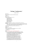
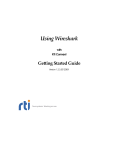
Figure 1.1. Data-Centric Publish-Subscribe application model.
Applications, whose operation is mainly data-driven, meaning that some action/computation is performed when data is ready, would be better served by
middleware platforms that seamlessly manage distribution of data from producers to
consumers. Such applications are often designed according to Data-Centric PublishSubscribe (DCPS) model [7], where the middleware creates a notion of a “global data
space” that is accessible to all interested applications (see Figure 1.1). Writing application under such a model brings many advantages. The biggest one being perhaps that
1
1. Introduction
..........................................
the communication requirements are specified by applications in a declarative way and
the middleware handles the data exchange automatically based on the declarations.
The aim of this thesis is to port Open Real-Time Ethernet (ORTE) communication
middleware to Android Operating System and then use it to develop an application for
mobile devices that will be capable of monitoring and controlling a mobile robot. The
application will use Java wrapper of the ported ORTE library.
This thesis is structured as follows. Chapter 2 describes the ORTE and the concepts
and protocol that it implements. Chapter 3 focuses at the process of porting ORTE
to Android. It provides overview of problems faced during the porting. Chapter 4
provides performance analysis of the ported ORTE library as well as an example of use
of the Java wrapper of the ported ORTE library. Chapter 5 describes the developed
application for controlling a mobile robot. It also provides basic information about the
robot in question.
2
Chapter 2
DDS, RTPS and ORTE
The popularity of DCPS model resulted in several standardization activities. Data
Distribution Service (DDS) for Real-time Systems [7] is an Object Management Group
(OMG) standard that specifies an API for applications based on the DCPS model.
Applications using this API are portable between different middleware platforms offering this API. The interfaces are specified in OMG Interface Definition Language
(IDL) [8, Chapter 7]. This means that the API is defined for many commonly used
languages such as C, C++, Python and others1 ).
The DDS API allows an application to declare that it produces certain data (identified
with a so called topic) or that it wants to receive (subscribe to) such a data. The
underlying middleware ensures that the stream of data is properly communicated from
one or more producers to one or more subscribers. Besides the basic data exchange
between publishers and subscribers, the middleware allows the applications to specify
many additional Quality-of-Service (QoS) parameters such as deadlines, reliability level,
data durability, etc. This not only simplifies the application design but also allows the
middleware to optimize the communication in many ways. The DDS standard specifies
only the API, not the underlying mechanisms that implement the data exchange.
The communication protocol that can be used to implement the functionality required by the DDS API is called the Real-Time Publish-Subscribe (RTPS) protocol [9].
The primary goal of RTPS is to provide interoperability between different DDS middleware platforms. This is achieved by defining a minimal set of requirements that
all implementations have to satisfy. Besides that, the standard defines many optional
advanced features as well as a way for implementing vendor specific extensions of the
protocol. The standard defines the protocol in a platform (transport) independent way
and then it defines the mapping onto the UDP/IP protocol. The protocol takes advantage of multicast communication when available, but works also in environments
without multicast support. Implementations can decide about trade-offs in resource
needs. Simple implementations can have small memory footprint but will need higher
network bandwidth. Other implementation can use abundance of local memory to
highly optimize the communication and thus save network bandwidth.
The RTPS protocol has the following features that make it an interesting option for
distributed real-time applications.
.
1
No single point of failure Every application has a complete model of the whole
network. Crash of a single application influences only the applications that need
data from it. However this holds only in trusted networks (either local or VPN).
On public networks data sent through RTPS could be tampered with. The attacker
could pretend to be a legitimate node and inject arbitrary data into the network,
that would be delivered to subscribers of specific topic.
) See http://www.omg.org/spec/#Map
3
2. DDS, RTPS and ORTE
.
.
.....................................
Redundancy Multiple publishers can publish the same “topic”. If one publisher fails,
subscribers will be automatically switched to another one. This is illustrated in
Figure 1.1 where “Presure” information is published by two applications.
Application discovery Built-in discovery protocol ensures that applications can discover each other as well as the topics they publish or are subscribed to.
Besides several commercial implementations of the RTPS protocol, at least two open
source implementations exist: OpenDDS [10] and ORTE [16]. OpenDDS appears to be
more mature. It implements both the DDS API and the underlying RTPS protocol. It
is implemented in C++ and provides bindings for Java. OpenDDS is built on top of
the ACE1 ) abstraction layer to provide platform portability. OpenDDS also leverages
capabilities of CORBA implementation called TAO2 ).
ORTE, another open source RTPS implementation, provides its own API instead of
the DDS API. The reason is that ORTE development started before the DDS standard
was finished. ORTE is implemented in C and includes a small portability layer that
allows it to run on many popular platforms including Linux, Windows, MacOS and
FreeBSD. Unfortunately, ORTE implements the RTPS protocol according to the draft
of the RTPS specification [14] and it would need some changes (see Section 2.1) in
order to be compliant with the current specification. The ORTE library was originally
created by Ing. Petr Smolík and Ing. Pavel Píša, Ph.D. [15] and it’s Java wrapper was
originally created by Ing. Lukáš Pokorný [13].
2.1 Compatibility of ORTE with the Latest RTPS
standard
ORTE is one of the first implementations of the RTPS protocol. In fact it was a proof
of concept implementation intended for testing of completeness and self-consistency of
the RTPS specification.
RTPS is standardized by the OMG as the “RTPS Wire Protocol”. ORTE was implemented using [14] (referred to as RTPS V1.0). The RTPS standard was later renamed to
“The RTPS Wire Protocol DDS Interoperability Wire Protocol Specification”. Current
version of this specification is V2.1 [9] (referred to as RTPS V2.1).
The changes from RTPS V1.0 to V2.1 are the subject of this section. We will demonstrate them on the current state of ORTE implementation. We describe the changes
needed for ORTE to be compatible with the RTPS V2.1.
2.1.1
Mapping of objects in ORTE to the RTPS V2.1
Many objects used in ORTE were renamed in the RTPS V2.1. In order to make it easier
to track changes in the new standard we make a table (2.1), that maps old names of
objects used in ORTE to names of similar objects in RTPS V2.1.
For the purpose of Section 2.1.2 we define a few terms. These definitions reflect
the fact that ORTE has it’s own API instead of the DDS one. By a Participant we
mean a communication node on a network, that contains Publishers and Subscribers.
This could be any application running on any node in the network. For our needs the
word Publisher will be equivalent to a Writer and Subscriber to a Reader. Writers and
Readers are collectively called Endpoints. For detailed description of RTPS structure
see [9, Section 7.4.1].
1
2
) http://www.theaceorb.com/product/aboutace.html
) http://www.theaceorb.com/
4
........................
2.1 Compatibility of ORTE with the Latest RTPS standard
Name in ORTE
Name in the RTPS V2.1
CSTReader
(Stateful)Reader
CSTRemoteWriter
CSChangeFromWriter
WriterProxy
ChangeFromWriter
CSChange
CSChangeForReader
CacheChange
ChangeForReader
CSTRemoteReader
CSTWriter
ReaderProxy
(Stateful)Writer
Related Sections
in the RTPS V2.1
8.2.8 (description),
8.4.10 (implementation)
8.4.10.4
8.4.10.5 (description),
8.4.12.3 (illustration)
8.2.3
8.4.7.6 (description),
8.4.9.3 (illustration)
8.4.7.5
8.2.7 (description),
8.4.7 (implementation)
Table 2.1. Mapping of ORTE objects to similar objects in the RTPS V2.1 standard.
2.1.2
List of required changes to ORTE
By analyzing the Platform Independent Module [9, Section 8] and by comparing it with
the ORTE implementation, we can write a list of changes that need to be done in order
for ORTE to be compatible with the RTPS V2.1.
1. UDPv6 support It is referrenced to as one of the kinds of transport in Locator t
type. For more information see [9, Table 8.2 in Section 8.2.1.2].
2. Data with key RTPS V2.1 introduced a new type of data objects – data with key.
This allows to distribute a set of data instances (as opposed to a single data instance)
under a single topic. A part of the data instance, called a key, is used to distinguish
between different instances. For more information see [9, Table 8.2 in Section 8.2.1.2].
3. Stateless Readers and Writers RTPS V2.1 provides two reference implementations
of Readers and Writers, namely Stateless and Stateful. They differ by the amount of
state they store on matched remote endpoints. For detailed description see [9, Section 8.4.3]. RTPS V1.0 uses only the Stateful variant.
4. Discovery protocols RTPS V1.0 uses a special application called Manager that runs
on every node and manages automatic discovery of applications both on the same
node and on remote nodes. The VAR submessage is used for exchange of information
about QoS parameters, topic’s type and name, etc. For more details see [14, Section 5.1].
RTPS V2.1 replaces this with the Simple Participant Discovery Protocol and the
Simple Endpoint Discovery Protocol that do not need the manager. According to
[9, Section 8.5.3.3.1, Section 8.5.3.3.2], the SPDP protocol uses data with key and
the Stateless implementation of Reader and Writer.
5. In-line QoS RTPS V2.1 makes it possible to include QoS parameters directly in each
Data submessage. As per [9, Section 8.7.1], the in-line QoS is used “in case a Reader
does not keep a list of matching remote Writers or the QoS parameters they were
configured with”. This is the case for StatelessReader.
6. Removal of VAR submessage The VAR submessage is removed from the RTPS V2.1
as it is now obsolete due to the introduction of the SEDP and in-line QoS.
5
Chapter 3
Porting to Android
Android is one of the most popular and proliferated mobile operating systems. It is
running on wide variety of devices ranging from mobile phones and tablets to home media centers and digital cameras. This makes it interesting for soft real-time application
developers.
To develop applications for Android, Google offers Android Software Development
Kit (SDK) and Android Native Development Kit (NDK). SDK is used for applications written in Java whereas NDK allows to use native C/C++ code in applications.
Android uses Google’s implementation of Java Virtual Machine (JVM) called Dalvik
VM.
Having an RTPS implementation running on Android brings interesting possibilities
of using Android devices to control and/or monitor applications that already use RTPS
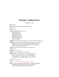
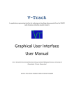
protocol. This was, in fact, the primary motivation for the porting effort. The Flamingos robotic team has built two mobile robots [17] that use RTPS and a desire to be able
to control the robots via a mobile phone was expressed. One such robot is depicted in
Figure 3.1.
In this Chapter we look at Android’s permission model in Section 3.1. We provide
an overview of the porting process in Section 3.2 and describe some technical details of
the porting in Section 3.3.
Figure 3.1. Controlling the robot with an Android phone.
6
....................................
3.1
3.1 Android Permission Model
Android Permission Model
In this section we will discuss Android’s security basics, that needed to be taken into
account during the ORTE porting and later during development of the robot monitoring
and control application.
Android uses a permission-based security model. Every application is assigned a
unique Linux user ID1 ) at the time of installation. During the installation process,
the application’s manifest is analyzed for permissions that the application declares as
required and only these permissions could be utilized by the application in the future.
It is important to say that the permissions are not enforced by the Dalvik VM, but
rather they are enforced at the kernel level. This way it is possible to completely sandbox applications on an Android device. For both, the Java and the native code, the
same permissions apply. It is therefore irrelevant whether a permission is requested
through calling a specific Java function provided by the Android API or through a system call from the native code. Applications using ORTE on Android require permission
to create network sockets – android.permission.INTERNET.
More detailed description of Android’s security model can be found in [3].
3.2
Overview of the porting process
I considered two possible approaches to the porting of ORTE. The first involved writing
a pure Java implementation of the RTPS protocol from scratch, the second was to
use an already existing Java wrapper, which makes use of the original native ORTE
library through the Java Native Interface (JNI) and make it Android-compatible. After
thorough consideration I’ve decided to go the Java wrapper way. Mostly because the C
code has been in use for quite some time and could be viewed as stable. On the other
hand, if I had chosen to write a new implementation of the protocol, it would require
extensive testing and would significantly slow the porting process.
.
..
.
In a nutshell, the process of porting was the following.
Update Java wrapper that uses Java Native Interface (JNI) and make it Android
compatible.
Fix bugs that have not demonstrated themselves under the Oracle’s VM.
Add support for Android build system.
Make Java version of ORTE Manager application (see Section 2.1.2 for details about
Manager) to overcome problems with execution and termination of native processes.
1
) It is possible for two or more applications from the same developer (i.e. signed with the same private
key) to share the same user ID.
7
3. Porting to Android
3.3
.......................................
Technical Details
In this section we take a closer look at some problems I faced in the process of porting
the ORTE library and their solution.
3.3.1
Class Loading
In order to be able to call Java object’s methods or access it’s fields from the C code
through the JNI, we first need to get the associated method ID or field ID. These
IDs are returned by the JNI functions GetMethodID and GetFieldID, respectively.
These functions need to know the class of the Java object. This is facilitated by the
FindClass function that accepts a class name as the parameter and invokes the class
loader associated with the current native function to load and link the named class [12].
According to the Android Documentation [4, FAQ: Why didn’t FindClass find my
class?] Android’s Dalvik VM uses the loader associated with the method at the top of
the interpreted stack, or if there is not one (the thread was just attached to the VM),
it uses the “system” class loader, for FindClass calls. The “system” class loader does
not see ORTE Java classes.
To overcome this, we use the JNI OnLoad function1 ). Any FindClass calls made from
there will happen in the context of the class loader of class that initiated the process
of loading the shared library. The JNI OnLoad function is called by the VM during this
loading process.
We take the class loader object of class org.ocera.orte.JOrte and make it a global
reference inside the VM by calling NewGlobalRef. Then we store the created reference
in a static global variable. This is to make it accessible for later class look-ups.
To perform a class look-up using the stored class loader object, we need to pass
the name of the requested class to it’s findClass method. We do this by means of
the JNI function CallObjectMethod, which takes as a parameter the method ID of
the findClass method. To speed-up future look-ups, we use the fact that the stored
class loader has been turned into a global reference, so we need to get the required
method ID only once, because it will remain the same. We get the method ID inside
the JNI OnLoad function and store it in a static global variable. The class loader object
stores references to already looked-up classes and requires the user to invoke method
findLoadedClass during subsequent look-ups of such classes.
To simplify the described class loading process inside the JNI code, I wrote a C function that first invokes the findLoadedClass method and if unsuccessful (the requested
class was not yet looked-up), invokes the findClass method.
3.3.2
Direct ByteBuffer
In this section we first describe the Java ByteBuffer class, then we elaborate on why
it is used in ORTE. Next we describe how it was previously used in the Java wrapper
and what problems that caused. Last, we take a look at adopted solution.
According to [11] ByteBuffer provides get and put methods that read and write
values of primitive data types, translating them to and from sequences of bytes in a
particular byte order. By default Big-Endian is used. There are two types of ByteBuffers (direct and non-direct) that differ in the way the VM performs I/O operations
upon them.
1
) For implementation see:
http://rtime.felk.cvut.cz/gitweb/orte.git/commit/b2b73b5c892eb04fc4822340fe9fef3bb99d4e31
8
.......................................
3.3 Technical Details
During the process of sending/receiving new data through ORTE, the data first need
to be serialized/deserialized. We use java.nio.ByteBuffer to accomplish this in the Java
wrapper. Upon new data’s arrival a C callback function is called by ORTE. The role
of this callback is to hand over the data to Java.
Previously the received data were copied from an internal ORTE buffer to a nondirect ByteBuffer, while the byte order of the received data was ignored and was
assumed to always be Big-Endian. This caused data received from hosts that use LittleEndian byte order to be unreadable. The sending of data was handled analogously to
their reception, so we will not describe it.
Now a direct ByteBuffer is used1 ). This made it possible to merge the internal
ORTE buffer with the ByteBuffer. They both now share the same memory region
to store elements and it is no more necessary to copy data between the C and Java
buffers. This reduced the overhead of sending/receiving data. Further, when new data
are received by ORTE and the C callback function is called, a byte order of the used
ByteBuffer is set in accordance with the received data. For more information about
the receive callback function, see Section 4.2.
Though it seems that the direct ByteBuffer is an excellent solution to mentioned
strugles, there is one limitation. The JNI standard defines that the function needed
to access direct ByteBuffer is optional to implement (see [12, Function GetDirectBufferAddress]). Fortunately many major implementations (including Oracle’s VM,
OpenJDK and Dalvik) choose to implement it, because it is used in cooperation with
OpenGL for graphics drawing. However, some exotic implementations need not implement it and the Java wrapper will not work with them.
3.3.3
64-bit Support
In the Java wrapper pointers to C structures are stored in Java fields for later use. For
example each publisher is assigned an instance of ORTEPublication structure upon its
creation for future manipulation, the most important being the possibility to publish
new data.
Java specification do not offer a data type specifically intended for storing pointers
like the C types intptr t, ptrdiff t or size t, so initially pointers were stored in the
Java’s int type, which is 32-bit wide. This works well on current versions of Android,
because most devices use 32-bit ARM based CPU, but does not work if used with
Oracle’s VM on a 64-bit OS. In order to overcome this, we use2 ) long fields (64-bit) to
store pointers instead of int fields. This is also the recommended way by Google [4,
64-bit Considerations] to store pointers on Android.
3.3.4
Use of WifiLock and MulticastLock
Android makes extensive use of power-saving features. One of them is the Wi-Fi Power
Save Polling (PSP) mode [6]. When this mode is entered, the device asks Wi-Fi Access
Point to cache all the downlink frames intended for that device. Cached frames could be
delivered during a wake-up mode that is entered either in order to transmit data or to
1
) For implementation, see:
http://rtime.felk.cvut.cz/gitweb/orte.git/commit/5e3acad2883da79c29458d5965d3dad8cbf629f7,
http://rtime.felk.cvut.cz/gitweb/orte.git/commit/c16934ed44af3add2d33c4630a9a29e0228830fd,
http://rtime.felk.cvut.cz/gitweb/orte.git/commit/8a64c855d6b39383104939877d3248571d949c71
2
) For implementation, see:
http://rtime.felk.cvut.cz/gitweb/orte.git/commit/b0dec948790009768c3e9fdc7a904f2056c945a9
9
3. Porting to Android
.......................................
retrieve cached data. Wake-up mode could be also entered by sending a PS-Poll frame.
After the last cached packet is received, the device enters the PSP mode again. I found
out that the PSP mode affects packet delay as well as packet delay variation. This
is of particular importance in case of data being sent by ORTE at higher frequencies.
Android allows a program to switch to Continuously Aware Mode (CAM) by acquiring
WifiLock in the WIFI MODE FULL HIGH PERF mode that is available since Android 3.1.x.
After an application acquires this lock the Wi-Fi module will be kept in CAM even when
the device enters sleep mode.
I measured the ping responses with the WifiLock both acquired and released. I
used 1,000 packets sent at the interval of 200 milliseconds. The results can be seen in
Table 3.1.
WifiLock taken
Yes
No
Packet loss
Min. RTT [ms]
Avg. RTT [ms]
Max. RTT [ms]
0.9%
1.2
3.3
177.2
0.2%
1.9
59.6
351.7
Table 3.1. Comparison of Wi-Fi ping latencies with and without WifiLock.
Furthermore the PSP mode could cause issues with some Wi-Fi Access Points that
do not support it. According to [5] this could lead to Wi-Fi connection being lost.
ORTE can be configured to use a multicast communication mode. Android, by
default, ignores the incoming multicast traffic for power-saving reasons. In order to
receive it, the program has to acquire the MulticastLock.
Both mentioned locks require specific Android permission (see Section 3.1) to be
granted to an application using them. Specifically the WifiLock requires the WAKE LOCK
permission and the MulticastLock requires the CHANGE WIFI MULTICAST STATE permission.
3.3.5
Java Manager
A Java version of the native ORTE Manager was created to overcome problems with
execution and termination of native processes. For the role of the Manager see Section 2.1.2.
The Java version was created by adding a wrapper around the ORTE functions used
by the native Manager. The only functionality required on the Android is the possibility
for the Java Manager to see other communication nodes on the network. That is
why the only currently implemented feature of the native Manager is the possibility
to pass an option specifying IP addresses of nodes to the underlying ORTE functions.
However, Manager’s wrapper could be easily extended to pass another options to ORTE
functions.
10
Chapter 4
Evaluation
The ported ORTE Java wrapper was evaluated by writing a simple application (Section 4.1) and comparing the performance of the native and Java implementations (Section 4.2).
4.1
Example Android Application
Figures 4.3 and 4.4 show code of a simple publisher and subscriber. First an application
creates a DomainApp object, then registers the data type (see Figure 4.2) that it uses
and finally registers a publisher or subscriber. Publisher can publish new data by
calling the send method. Subscriber receives data in the callback method. In order
for applications to find each other a manager application (see Figure 4.1) is needed.
import org.ocera.orte.*;
public class ExampleManager {
public static void main(String[] args) {
Manager manager = new Manager();
while(true) {
try {
Thread.sleep(1000);
} catch(Exception e) {
e.printStackTrace();
}
}
}
}
Figure 4.1. Code of a simple Java Manager.
4.2
Performance Comparison
To have a basic understanding about the overhead of the Java wrapper used for writing
Android applications, a set of experiments was conducted. I created a publisher and
a subscriber as applications in both C (native) and in Java. The publisher tries to
publish data as fast as possible. Because both the publisher and the subscriber were
configured as “reliable”, ORTE ensures that no publication gets lost and the subscriber
receives all the published data. Both the publisher and the subscriber were run on
the same device to measure the performance of the middleware itself rather than the
11
4. Evaluation
...........................................
import org.ocera.orte.*;
import org.ocera.orte.types.*;
public class ExampleData extends MessageData {
public short data = 1;
public ExampleData(DomainApp domainApp, String newTopic) {
super();
this.setTopic(newTopic);
domainApp.regNewDataType("example_type",
getMaxDataLength());
}
@Override
public void write() {
buffer.rewind();
buffer.putShort(this.data);
}
@Override
public void read() {
buffer.rewind();
this.data = buffer.getShort();
}
@Override
public int getMaxDataLength() {
return ORTEConstant.SHORT_FIELD_SIZE;
}
}
Figure 4.2. Code of a simple Java Data type class.
performance of the underlying network. I measured how long does it take to publish
ten thousand integer values. The experiments were run on three different devices Sony
Ericsson Xperia Ray with Android 4.0.4, Google Nexus 7 with Android 4.3 and a PC
with Intel Core i7-3520M CPU running at 2.90 GHz with OpenJDK 7. The results can
be seen in Table 4.1.
Pub
C
Java
C
Java
→
→
→
→
→
Sub
C
Java
Java
C
Xperia
2.2 s
10.3 s
10.1 s
2.6 s
Nexus 7
2.3 s
6.8 s
6.3 s
2.5 s
PC
0.31 s
0.78 s
0.78 s
0.31 s
Table 4.1. Performance comparison of native code and Java wrapper. Time needed for
publication of 10,000 integer values.
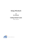
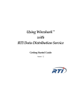
The relative slowdown of the Java implementation compared to the native one is
depicted in Figure 4.5. It can be seen that Dalvik VM performance has improved
between version 4.0.4 and 4.3 (or that it runs better on Nexus 7 hardware). OpenJDK
performs even better than Dalvik VM. There is no slowdown in Java → C case and in
both cases with the subscriber in Java, the performance is the same.
12
....................................
4.2 Performance Comparison
import org.ocera.orte.*;
import org.ocera.orte.types.*;
public class ExamplePublisher {
public static void main(String[] args) throws Exception {
NtpTime persistence = new NtpTime(3);
int strength = 100;
DomainApp appDomain = new DomainApp(
0, DomainProp.defaultPropsCreate(), null, false);
ExampleData datamsg = new ExampleData(appDomain, "example_topic");
PublProp publProp = new PublProp("example_topic",
"example_type", persistence, strength);
Publication pub = appDomain.createPublication(publProp, datamsg);
while(true) {
Thread.sleep(1000);
pub.send(datamsg);
datamsg.data++; } } }
Figure 4.3. Code of a simple Java Publisher.
import org.ocera.orte.*;
import org.ocera.orte.types.*;
public class ExampleSubscriber extends SubscriptionCallback {
public static void main(String[] args) throws Exception {
NtpTime deadline = new NtpTime(10);
NtpTime minSeparation = new NtpTime(0);
DomainApp appDomain = new DomainApp(
0, DomainProp.defaultPropsCreate(), null, false);
ExampleData datamsg = new ExampleData(appDomain, "example_topic");
SubsProp subProps = new SubsProp(
"example_topic", "example_type",
minSeparation, deadline,
ORTEConstant.IMMEDIATE,
ORTEConstant.BEST_EFFORTS, 0);
Subscription sub = appDomain.
createSubscription(subProps, datamsg, new ExampleSubscriber());
while(true)
Thread.sleep(1000); }
public void callback(RecvInfo info, MessageData msg) {
if (info.getRecvStatus() == ORTEConstant.NEW_DATA)
System.out.println(((ExampleData)msg).data); } }
Figure 4.4. Code of a simple Java Subscriber.
13
4. Evaluation
...........................................
Figure 4.5. Relative slowdown of implementations.
The reason for Java subscriber being slow is mostly because of the way Java receive
callback is called from the native code. There is a native receive thread that handles
received packets as they arrive. If new data were received, a native callback function is
called from within this thread. The callback is passed a buffer containing the received
data as well as an instance of ORTERecvInfo structure containing information about
the data (e.g. endianess, topic, sequence number). In case of Java subscribers this
callback is implemented as a JNI function that first attaches itself to the Java VM to
have access to Java classes and existing objects. It then creates a new Java object,
that is essentially a Java version of the ORTERecvInfo structure. After this, it sets
byte order of Java’s direct ByteBuffer according to ORTERecvInfo and calls a method
of an Java object, which represents the received data, to deserialize the data stored
in the ByteBuffer. When this is done an application callback function is called with
the deserialized Java object as a parameter. After the Java callback returns the native
receive thread detaches itself from the Java VM.
As could be seen from the above description the main bottleneck lays in the fact
that the native receive thread, from which the Java wrapper’s receive callback function
is called, has to be attached to the Java VM and has to call many JNI functions that
copy a lot of data internally. As could be seen from performed measurements the drop
in throughput is significant.
A better way to call Java’s receive callback function would be to create a dedicated
Java thread reading from a custom message queue to which messages could be written
directly from the native receive callback function without the need to attach to the
Java VM. This is considered for future development.
14
Chapter 5
Demo application
In order to demonstrate functionality of the ported ORTE library, I wrote an application
in Java for remote control of a small robot. The application is called RoboDruid. It is
capable of displaying information received from an on-board Laser Range Finder, monitoring battery voltage and controlling robot’s motion. Robot’s hardware and software
is described in Section 5.1.
Robot’s motion is controlled by an accelerometer embedded in the Android device. To
suppress the noise, accelerometer output is filtered by a low-pass filter. We use standard
sensor API of Android in order to interface with the accelerometer. Section 5.2 expands
on the implementation of the demo application. Section 5.3 provides a user manual for
the developed application.
5.1
Demo Robot
This section introduces basics of ORTE’s use in the robot. Detailed description of
the robot’s hardware and software can be found in [17] and in the diploma thesis of
Ing. Michal Vokáč [19]. Here we will only describe parts of the robot, that are vital
for understanding how the different components of robot are connected together. This
information was used during the development of the demo application for Android.
The mobile robot being used was previously developed by the Flamingos robotic team
at the Faculty of Electrical Engineering at the Czech Technical University in Prague.
The robot was constructed in order to take part in Eurobot 2007 and similar indoor
robotic contests.
Later a decision was made to construct a new robot for competitions and use the
former for demonstration purposes. It is being used mainly at events like Doors Open
Days or various exhibitions. I have made no changes to it’s hardware or software design.
5.1.1
Robot’s Hardware
The centerpiece of the Demo Robot is Main Controller Board (MCB) equipped with
MIDAM Shark microprocessing unit powered by Freescale MPC5200 CPU. The board
features CAN bus, 10/100T Ethernet, USB host bus. Detailed description of the board
can be found in [19, Section 4.5].
The robot is equiped with Hokuyo URG-04LX-UG01 Laser Range Finder that is capable of measuring distance from objects in front of the robot in polar coordinates.
Detailed sensor parameters can be found in [19, page 26]. The LRF sensor is connected
to USB bus on the Main Controller Board.
Power to the robot is supplied by so called “PWR board”. This board includes three
independent switching power supplies delivering voltages 3.3 V, 5 V and 8 V. The board
continuously measures voltage levels on all three branches. Details of the board can be
found in [19, Section 4.3].
15
5. Demo application
........................................
The robot is geared by two BLDC motors controlled by so called “Driver board”.
The motors are driven by a PWM signal generated by the board. Detailed description
of the board can be found on pages 22–23 in [19].
For demo purposes, the robot was equipped with a small crane manipulator arm and
an electromagnet. The small crane arm is driven by a servomotor. Both the servomotor
and the electromagnet are controlled by so called “EB board”. Details about this board
can be found on pages 18–20 in [19]. Description of the robot’s manipulator design is
on pages 12–13 in [19].
The three previously mentioned boards (“PWR board”, “Driver board”, “EB board”)
are connected through CAN bus to the Main Controller Board.
The robot is equipped with a Wi-Fi router that is connected through Ethernet to
the Main Controller Board. We use this Wi-Fi interface to connect to the robot from
an Android device. Details about the router can be found in [19].
5.1.2
Robot’s Software
The robot’s Main Controller Board is powered by a Linux-based Operating System
(custom Linux flavor; includes only basic tools like BusyBox and Dropbear SSH server;
for more information see [19, Section 5.1]). There are few programs running on this
board that we will shortly describe:
.
..
cand application is used to send data between the Main Controller Board and other
boards connected to it through the CAN bus. This application receives CAN messages with specific IDs and publishes them as ORTE issues. The cand also works
in the opposite direction. It subscribes to certain ORTE topics and assembles CAN
frames from them. In other words, it serves as a bridge between ORTE and CAN.
hokuyod acquires data from LRF and publishes them on ORTE.
ortemanager maintains record of ORTE participants across the network.
5.1.3
Mapping of CAN Message IDs to ORTE Topics
In this section we take a look at various ORTE Topics used in the robot that are of
importance for the development of RoboDruid. We also map ORTE Topics to corresponding CAN Message IDs in Figure 5.1. The description of ORTE Topics uses ORTE
IDL language. It’s syntax is similar to that of the C language.
ORTE Topic
motion speed
pwr voltage
crane cmd
magnet cmd
CAN Message alias
CAN MOTION CMD
CAN PWR ADC1, CAN PWR ADC1
CAN CRANE CMD
CAN MAGNET CMD
CAN Message ID
0x21
0x41, 0x42
0x34
0x35
Table 5.1. Mapping of CAN Message IDs to ORTE Topics.
16
........................................
5.2 Implementation
struct motion_speed {
short left;
short right;
};
Figure 5.1. IDL code for topic motion speed.
struct pwr_voltage {
double voltage33;
double voltage50;
double voltage80;
double voltageBAT;
};
Figure 5.2. IDL code for topic pwr voltage.
struct hokuyo_scan {
unsigned short data[681];
};
Figure 5.3. IDL code for topic hokuyo scan.
struct magnet_cmd {
unsigned short on;
};
Figure 5.4. IDL code for topic magnet cmd.
struct crane_cmd {
unsigned short req_pos;
unsigned short speed;
};
Figure 5.5. IDL code for topic crane cmd.
5.2
Implementation
In this section we describe some important aspects of implementation1 ) of the RoboDruid. Section 5.2.1 gives a basic overview of the application’s package structure. In
Section 5.2.2 we describe how the data from accelerometer are acquired and used for
robot’s motion control. In Section 5.2.3 we look on how the data received from robot’s
Laser Range Finder are processed and drawn.
1
) For complete source code of the application, see:
http://rtime.felk.cvut.cz/gitweb/orte.git/tree/HEAD:/orte/contrib/Robot_Demo
17
5. Demo application
5.2.1
........................................
Java Package Structure
The application is structured into four separate Java packages. The first one is called
GUI and consists of classes dealing with the main Activity’s1 ) creation and custom
View2 ) that handles the drawing of actual speed vector of the robot and visualization of received data from the Laser Range Finder onboard the robot. The second
one, called DataTypes, includes classes extending MessageData that describe the data
types for given topics sent through ORTE. The third, called Publishers, and fourth,
called Subscribers, define publishers and subscribers of different topics used in the
application.
5.2.2
Acquisition and Processing of Accelerometer data
Many today’s Android devices are equipped with a 3-axis accelerometer that is used
mainly in games and for changing screen orienation based on current direction of the
acceleration vector.
We use the accelerometer in order to control the angular and linear velocity of a
mobile robot. First, we will briefly look at Android’s SensorManager [2] and SensorEvent [1] API.
Access to built-in sensors is mediated by android.hardware.SensorManager class.
This manager allows a user to request data from a certain kind of sensor. The SensorManager then allows to register a callback listener class that will process the received data. This class contains a function onSensorChanged(SensorEvent event),
that is used for processing of new data received from the sensor and onAccuracyChanged(Sensor sensor, int accuracy), used for notification of change in sensor’s
accuracy.
Figure 5.6. Android SensorEvent API reference frame (Source: [1])
The data from sensor is delivered to the listener inside a SensorEvent object. Figure 5.6 shows coordinate system used by Android’s SensorEvent API.
The accelerometer measures the proper acceleration (i.e. relative to a free-fall in the
device’s reference frame) experienced by the device. For robot’s motion control, we
only need the x-axis and y-axis component of the acceleration vector.
The data produced by the sensor is susceptible to high frequency noise caused by
numerous factors. Perhaps the most important being the shaking of hands and deliberate attempt to “overload” the robot’s motors by tilting the device from side to side.
1
2
) http://developer.android.com/guide/components/activities.html
) http://developer.android.com/training/custom-views/index.html
18
.........................................
5.3 User Manual
In order to reduce the high frequency component we use a simple filter, that takes the
previous value of acceleration y[n − 1], the current measured value u[n] and calculates
new value of acceleration y[n].
Eq. 5.1.
y[n] = αy[n − 1] + (1 − α)u[n] ,
where α = 0.75.
We apply this formula to both the x-axis and y-axis component of the acceleration
vector. This filter is mentioned in the documentation of the SensorEvent API [1]. This
filtered acceleration vector is then used to calculate the required speeds of the left and
right motor of the robot.
5.2.3
Handling of received Laser Range Finder Data
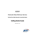
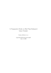
Figure 5.7. Visualization of Data published by the LRF.
The Laser Range Finder produces data in polar coordinates. The space around the
LRF is partitioned into equally sized circular sectors. There are 681 values published
through the hokuyo scan topic. Each value contains distance to the nearest obstacle
[in millimeters] in a specific circular sector.
This data is easily transformed to a Cartesian coordinate system that is used by
Android’s painting methods. Example of the visualized LRF data in the RoboDruid is
on Figure 5.7.
5.3
User Manual
Since the RoboDruid is intended for demonstration purposes, we present a thorough
step-by-step guide for RoboDruid’s compilation (Section 5.3.1) on Debian-like OS’s as
well as RoboDruid’s user manual (Section 5.3.2).
19
5. Demo application
5.3.1
........................................
Compilation
In order to compile RoboDruid on Debian-based systems the following packages must
be installed:
..
..
make (version 3.81 or higher)
ant
git
oracle-java7-installer1 )
As a next step, download Android NDK2 ) and SDK3 ). After extracting these you
need to launch shell and add few directories to the PATH environment variable:
$ export PATH=$PATH:<path-to-NDK>
$ export PATH=$PATH:<path-to-SDK>/platform-tools:<path-to-SDK>/tools
Next it is necessary to obtain “SDK Platform for Android 4.0.3”. To do this execute
command:
$ android update sdk --no-ui --all --filter android-15
During the installation user has to accept the “Android Software Development Kit
License Agreement”.
In the next step source code of ORTE and RoboDruid will be fetched. There are
many ways to accomplish that. I suggest cloning the GIT repository. You do this by
issuing:
$ git clone git://rtime.felk.cvut.cz/orte
$ cd orte
In the next step a local properties file will be created for both the Android library
and the RoboDruid application:
$ android update project -p orte/libaorte
$ android update project -p orte/contrib/Robot_Demo
To build the native code you have to issue the following commands:
$ cd orte/libaorte
$ ndk-build
Now, it is possible to build the Java code and sign the application package with a
debug key:
$ cd ../contrib/Robot_Demo
$ ant debug
At this point user should have successfully build a package ready for deploying onto
an Android device. One possibility to install the application directly onto the device is
to connect the device to PC’s USB port and use the ADB application from the SDK
to do the installation:
$ adb install bin/RoboDruid-debug.apk
After the installation begins, it is necessary to confirm application’s permissions on
the Android device’s screen.
1
) Available from webupd8team/java ppa repository; could be added to local repositories by issuing command $ sudo add-apt-repository ppa:webupd8team/java
2
) Available from http://developer.android.com/tools/sdk/ndk/index.html
3
) Available from http://developer.android.com/sdk/index.html
20
.........................................
5.3.2
5.3 User Manual
User Instructions
Power-up the robot by flipping the power button and wait for it to finish initialization
(indicators of function of individual components on the robot’s display will turn green).
In order to connect to the robot’s Wi-Fi interface, you have to first setup a connection
profile for the robot’s Access Point. Open Settings dialog on the Android device, tap
on Wi-Fi and select “CTU demo” AP and enter “demorobot” as a passphrase, then
save the profile and connect to it.
When the connection is established you can start RoboDruid. To do that, tap on
it’s icon in the device’s menu. After the application’s start-up, the screen on Figure 5.8
will appear.
Figure 5.8. RoboDruid’s default screen.
To start receiving data (subscribe to ORTE topic hokuyo scan) from robot’s onboard
Laser Range Finder, you need to tap on the gray circular sector located in the middle of
the screen. Successful subscription creation will be announced by text “Hokuyo LRF:
ON”. To unsubscribe tap again in the same region. Successful subscription cancellation
will be announced by text “Hokuyo LRF: OFF”.
Figure 5.9. RoboDruid’s menu.
To control robot’s motion (publish topic motion speed), push in the top left corner
of the screen and hold until text “Motion Control: ON” appears at the bottom of the
screen.
21
5. Demo application
........................................
In order to monitor current speed of the robot, single tap in the top left corner of
the screen. A text “Speed Monitor: ON” confirming successful subscription to ORTE
topic motion speed should appear. The orientation of the axis is analogous to that in
Figure 5.6. The vertical axis of the displayed cross represents angular velocity of the
robot. The horizontal axis represents linear velocity of the robot. To unsubscribe tap
again in the same region. Succesful subscription cancellation will be announced by text
“Speed Monitor: OFF”.
To change position of the robot’s crane, press the Menu button and select Crane (see
Figure 5.9). The current position of the crane is written next to it in the menu. The
default assumed position at RoboDruid’s start is “up”.
To activate the electromagnet, that is located at the end of the crane’s arm, press the
Magnet (see Figure 5.9) button in the menu. Current status of magnet is represented
by a check-box next to it’s entry in the menu. If the magnet is enabled, the box will
be checked and vice versa.
Figure 5.10. RoboDruid’s Voltage Monitor.
It is possible to monitor current voltage on different branches used inside the robot
as well as it’s battery voltage. To do that, tap on “Voltage monitor” in the menu, a
dialog showing the voltages will pop-up (see Figure 5.10). The displayed values are
continuously updated.
Figure 5.11. RoboDruid’s Managers Dialog
22
.........................................
5.3 User Manual
It is possible to enter IP addresses of other computers connected to the robot’s Wi-Fi
AP. This could be useful for example to receive current speed of robot, that is being
controlled by an application launched on the computer, on the Android device. To
do this select the “Fellow managers” option in menu. Next, a dialog will pop-up (see
Figure 5.11). IP addresses of neighboring computers could be entered into the text
box and separated by a colon. By default, only the IP address of the Main Controller
Board (10.1.1.1) is entered. The dialog also displays current IP address associated with
the Wi-Fi interface as well as the name (SSID) of the Wi-Fi network that the device
is currently connected to. After entering IP addresses of neighboring computers in the
box, confirm new settings by tapping OK. After this a new manager domain will be
created. It will take approximately one minute for applications running on nodes across
the network to find each other through the newly created manager domain. If you do
not want to wait, just restart RoboDruid. It will remember the list of neighboring
computers across restarts.
As this application is intended for demonstration purposes, unexpected situations
can occur, such that could lead to robot’s damage or cause an injury to someone. In
case of such an event, pressing the Home or Power button will stop robot’s movement.
23
Chapter 6
Conclusion
In this work an application to monitor and control mobile robots using an Androidbased mobile device was developed. This application can be used on occasions like
Doors Open Days. In order to develop the application, we first had to port the ORTE
library to Android.
We successfully ported the ORTE library and it’s Java wrapper to Android. As a
result many bugfixes and changes were made to the Java wrapper, the most important
being:
..
.
Creation of Java variant of the ORTE Manager.
Ability to receive and publish data in both Little-Endian and Big-Endian byte orders.
Reduction of overhead during data’s publication/reception achieved by eliminating
excessive copying of elements between internal ORTE buffers and Java wrapper
buffers.
We assesed performance of the ported Java wrapper and compared it with that of
native ORTE. The ported wrapper as well as the developed mobile application were
thoroughly tested. We have also analyzed differences between current state of the ORTE
implementation and the changes necessary for it to be compatible with the RTPS V2.1
standard.
Shorter version of this thesis was published at the Real-Time Linux Workshop [18].
24
References
[1] Google, Inc. Android Developers, SensorEvent documentation. Online:
http://developer.android.com/reference/android/hardware/SensorEvent.html,
visited 5/2014.
[2] Google, Inc. Android Developers, SensorManager documentation. Online:
http://developer.android.com/reference/android/hardware/SensorManager.html,
visited 5/2014.
[3] Google, Inc. Android Security Overview. Online:
https://source.android.com/devices/tech/security/, visited 5/2014.
[4] Google, Inc. JNI Tips. Online:
http: / / developer . android . com / training / articles / perf-jni . html,
visited
10/2013.
[5] Intel Corporation. Power save polling (PSP) causes connection issues with access
points. Online:
http://www.intel.com/support/wireless/wlan/sb/cs-006205.htm, visited 10/2013.
[6] Laird Technologies, Inc. Power save polling. Online:
http://www.summitdata.com/Documents/Glossary/knowledge_center_p.html#psp,
visited 10/2013.
[7] Object Management Group.
Version 1.2. Online:
Data Distribution Service for Real-time Systems,
http://www.omg.org/cgi-bin/doc?formal/07-01-01.pdf, visited 5/2014, Jan 2007.
[8] Object Management Group.
Common Object Request Broker Architecture
(CORBA) Specification, Version 3.1, Part 1: CORBA Interfaces.
Number
formal/2008-01-04. [Online], 2008.
[9] Object Management Group. The Real-time Publish-Subscribe Wire Protocol,
DDS Interoperability Wire Protocol Specification (DDS-RTPS). Online:
http://www.omg.org/spec/DDSI-RTPS/2.1, visited 5/2014, Nov 2010.
[10] OpenDDS. OpenDDS web site. Online:
http://www.opendds.org/, visited 5/2014.
[11] Oracle, Corp. Java Platform SE 7, ByteBuffer documentation. Online:
http://docs.oracle.com/javase/7/docs/api/java/nio/ByteBuffer.html, visited
5/2014.
[12] Oracle, Corp. Java SE Documentation, JNI Functions. Online:
http://docs.oracle.com/javase/7/docs/technotes/guides/jni/spec/functions.
html, visited 5/2014.
[13] Lukáš Pokorný. Podpůrné nástroje pro RTPS komunikaci.
Fakulta elektrotechnická, ČVUT, 2005.
Master’s thesis,
[14] Real-Time Innovations, Inc. RTPS Wire Protocol Specification, Version 1.0. Online:
25
References
............................................
http://orte.sf.net/rtps1.2.pdf, visited 5/2014, Feb 2002.
Draft Document
Version: 1.17.
[15] Petr Smolík and Pavel Píša. ORTE: The Open Real-Time Ethernet. Technical
report, Czech Technical University in Prague, 2008. Online:
http://orte.sf.net/rtn08_orte.pdf, visited 5/2014.
[16] Michal Sojka. ORTE web site. Online:
http://orte.sf.net/, visited 5/2014.
[17] Kh. Tran Duy, M. Žídek, J. Benda, J. Kubias, and M. Sojka. Autonomous Robot
Running Linux for the Eurobot 2007 Competition. In Ninth Real-Time Linux
Workshop. Real-Time Linux Foundation, 2007.
[18] Martin Vajnar, Michal Sojka, and Pavel Píša. Porting of Real-Time PublishSubscribe Middleware to Android. In Fifteenth Real-Time Linux Workshop. RealTime Linux Foundation, 2013.
[19] Michal Vokáč. Demonstrační robotická platforma. Master’s thesis, Fakulta elektrotechnická, ČVUT, 2012.
26
Appendix A
Abbreviations
ACE
Adaptive Communication Environment
ADB
Android Debug Bridge
ADT
Android Development Tools
AP
API
BLDC
Access Point
Application Programming Interface
Brushless Direct Current electric motor
CAM
Continuously Aware Mode, sometimes also called Constantly Awake
Mode
CAN
Controller Area Network
CORBA
CPU
DCPS
Common Object Request Broker Architecture
Central Processing Unit
Data-centric publish-subscribe
DDS
Data Distribution Service
GUI
Graphical User Interface
IDL
Interface Description Language
IP
Internet Protocol
JNI
Java Native Interface
JVM
Java Virtual Machine
LRF
Laser Range Finder
MCB
Main Controller Board
NDK
Native Development Kit
OMG
Object Management Group
ORTE
Open Real-Time Ethernet
OS
Operating System
PC
Personal Computer
PSP
Power Save Polling
PWM
QoS
RTPS
SDK
Pulse-width Modulation
Quality of Service
Real-Time Publish-Subscribe
Software Development Kit
SEDP
Simple Endpoint Discovery Protocol
SPDP
Simple Participant Discovery Protocol
SSH
Secure Shell
27
A Abbreviations
.........................................
SSID
Service Set Identifier
TAO
The ACE ORB
UDP
User Datagram Protocol
USB
Universal Serial Bus
VM
Virtual Machine
28
Appendix B
Contents of the Attached CD
.
.
.
.
doc
thesis.pdf – electronic version of this thesis
application
RoboDruid.apk – installation package of the developed RoboDruid application
29