1
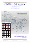
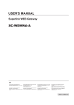
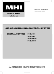
SC-WGWNA-B Product Specification Ver 1.0
Document No. ISTZ09025 Decmber 1, 2009
NEW SUPERLINK SYSTEM
POWER CALCULATION WEB GATEWAY
PRODUCT SPECIFICATION
MODEL : SC-WGWNA-B
Product Drawing No.: PSZ006A017DA
Ver. 1.0
December 1, 2009
MITSUBISHI HEAVY INDUSTRIES, LTD.
AIR-CONDITIONING & REFRIGERATION
SYSTEMS HEADQUARTERS
1
SC-WGWNA-B Product Specification Ver 1.0
Document No. ISTZ09025 Decmber 1, 2009
1. INTRODUCTION
1.1 SCOPE
This product specification is applied to the WEB Gateway SC-WGWNA-B that connects a Control & Monitor
personal computer with the MITSUBISHI HEAVY INDUSTRIES’ “SUPERLINK” networks by the “WEB”*1
communication protocol. This document describes the specifications of the product as for December 1, 2009.
Any contents of this document may be changed without prior notification.
*1 This product uses the WEB HTTP communication protocol which is widely used in the Internet.
However, this Gateway is basically for use in a local LAN.
1.2 STANDARD PACKAGE
The standard package of this product includes the followings;
- A Gateway SC-WGWNA-B unit
- User’s manual
- Installation manual
- Power Consumption Calculation Utility Software CD-ROM
The following materials are not included in the standard package.
- Personal computer systems for monitor and control.
- LAN materials such as Ethernet cables, switching hubs and firewalls.
1.3 ENGINEERING WORK
“Engineering work” means technical service work such as dispatching engineers to the site, the address
allocation planning work, configuration of this Gateway, trial operation of the system and so on. These
engineering works may be paid services.
1.4 CUSTOMIZE WORK
This WEB Gateway is a kind of ready-made product.
not be supplied.
Customization of the functions of this Gateway will
1.5 CAUTION THAT PERFORMING OF THE MONTHLY CALCULATION
- We can not compensate when monthly calculation was not possible by the trouble of this Gateway.
- Because the monthly calculation by this data not conform to OIML (International Organization of
Legal Metrology), we cannot apply to public business.
- Please prepare the PC, spreadsheet such as EXCEL, a printer, a wattmeter, a gas flow meter that are
required for calculation.
2
SC-WGWNA-B Product Specification Ver 1.0
Document No. ISTZ09025 Decmber 1, 2009
2. SYSTEM ARCHITECTURE
2.1 SYSTEM DIAGRAM
Fig.2.1.1 shows a basic case of the new SUPERLINK communication system diagram of connection between
the Control & Monitor PC, the WEB Gateway and the SUPERLINK control networks.
Internet
Explorer
Control & Monitor PC
New SUPERLINK
System
Ethernet 10BASE-T or 100BASE-TX
connecting with a HUB or a cross cable
WEB Gateway
( SC-WGWNA-B )
SUPERLINK NO.1 network
IndoorUnit
IU-0
R
IndoorUnit
W
W
W
W
SUPERLINK NO.2 network
IndoorUnit
IU-0
IndoorUnit
IU-1
CELL 1
IU-2
Gas・Wattmeter
R
Gas meters and Watt meters should be
the followings;
・With non voltage contact pulse
transmitters.
・Pulse width : 100 ms or more
CELL 49
IU-1
IndoorUnit
pulse
P1
P2
P3
P4
CELL 48
CELL 0
Pulse signal wirings
R
CELL 47
R
IndoorUnit
IU-2
CELL 95
IndoorUnit
IU-62
IndoorUnit
IU-63
R
IndoorUnit
IU-62
R
IndoorUnit
IU-63
CELL No. allocation
From CELL 0 to CELL 95 can be allocated.
Skipping CELL No. is acceptable.
OutdoorUnit
OU-0
OutdoorUnit
OU-11
Fig. 2.1.1
OutdoorUnit
OU-0
OutdoorUnit
OU-11
Number of indoor units for one SUPERLINK
network
Max. 64 indoor units can be connected.
Number of outdoor units for SUPERLINK
network
Max. 12(recommended)
System Diagram (Basic case of the new SUPERLINK communication system)
3
SC-WGWNA-B Product Specification Ver 1.0
Document No. ISTZ09025 Decmber 1, 2009
Fig.2.1.2 shows a case of the new SUPERLINK communication system diagram of connection between the
building management system host computer, the WEB Gateway, and the SUPERLINK control networks along
with SUPERLINK option controllers such as SL1N, SLN2, SL3N. The SC-ADN adapter should be used for
connection of MHI’s single type packaged air-conditioner models.
Internet
Explorer
Control & Monitor PC
(Max. 4 PCs)
New SUPERLINK
System
Internet
Explorer
Ethernet
10BASE-T or 100BASE-TX
WEB Gateway No.1
( SC-WGWNA-B )
SUPERLINK No.1 network
CELL 0
IndoorUnit
IU-0
SUPERLINK No.2 network
IndoorUnit
R
IU-0
IU-1
CELL 1
SUPERLINK Adapter SC-ADN
CELL 49
R
Adapter
Single PAC
Indoor
IU-2
CELL 47
IndoorUnit
IU-62
R
CELL 95
IndoorUnit
IU-63
IU-63
SL2N
OutdoorUnit
OutdoorUnit
OU-0
OU-0
OU-11
R
CELL No. allocation
From CELL 0 to CELL 95 can be allocated.
Skipping CELL No. is acceptable.
SL1N
OutdoorUnit
Single
PAC
Outdoor
R
IndoorUnit
SL1N
R
IndoorUnit
IU-1
IU-2
WEB Gateway No.4
( SC-WGWNA-B )
CELL 48
IndoorUnit
IndoorUnit
WEB Gateway link
(Max 4 Gateways)
OutdoorUnit
Number of indoor units for one SUPERLINK
network
Max. 64 indoor units can be connected.
Number of outdoor units for SUPERLINK
network
Max. 12(recommended)
OU-11
Fig. 2.1.2 System Diagram (Option controller connected case of the new SUPERLINK communication system)
4
SC-WGWNA-B Product Specification Ver 1.0
Document No. ISTZ09025 Decmber 1, 2009
Fig.2.1.3 shows a case that 65 or more indoor units (up to 128 units) are connected to one SUPERLINK
communication system.
Compared to 64 units each on two SUPERLINK network systems (Fig.2.1.2), the network traffic is clouded,
so the communication speed to each indoor unit becomes slow. Then it is recommended that using two
SUPERLINK network systems.
To use the WEB Gateway in this system, it is required to switch the system program. (Please refer to the
configuration manual of the WEB Gateway.)
Internet
Explorer
Control & Monitor PC
Ethernet 10BASE-T or 100BASE-TX
connecting with a HUB or a cross cable
New SUPERLINK
System
Pulse signal wirings
pulse
WEB Gateway
( SC-WGWNA-B )
W
W
W
W
SUPERLINK NO.1 network
CELL 0
IndoorUnit
IU-0
R
Gas・Wattmeter
P1
P2
P3
P4
SUPERLINK NO.2 network
(Can not be used.
in this case.)
Gas meters and Watt meters should be
the followings;
・With non voltage contact pulse
transmitters.
・Pulse width : 100 ms or more
IndoorUnit
IU-1
CELL 1
IndoorUnit
IU-2
In case that an outdoor unit of combination systems
is used, more than 65 indoor units might be connected
to one SUPERLINK system.
In this case, SC-WGWNA-B is used in one SUPERLINK
system mentioned here.
R
CELL 95
IndoorUnit
IU-126
Otherwise, it is recommended that SC-WGWNA-B is used
in two SUPERLINK systems.
R
IndoorUnit
IU-127
SL1N
CELL No. allocation
From CELL 0 to CELL 95 can be allocated.
Skipping CELL No. is acceptable.
SL2N
Number of indoor units
Max. 128 indoor units can be connected.
OutdoorUnit
OU-0
Number of outdoor units
Max. 24(recommended)
OutdoorUnit
OU-23
Fig. 2.1.3
System Diagram (128 indoor units on one SUPERLINK communication system)
(New SUPERLINK communication system)
5
SC-WGWNA-B Product Specification Ver 1.0
Document No. ISTZ09025 Decmber 1, 2009
Fig.2.1.4 shows a basic case of the previous SUPERLINK communication system diagram of connection
between the building management system host computer, the WEB Gateway and the SUPERLINK control
networks.
Internet
Explorer
Control & Monitor PC
Previous SUPERLINK
System
Ethernet 10BASE-T or 100BASE-TX
connecting with a HUB or a cross cable
WEB Gateway
( SC-WGWNA-B )
SUPERLINK NO.1 network
IndoorUnit
IU-0
R
IndoorUnit
W
W
W
W
SUPERLINK NO.2 network
IndoorUnit
IU-0
IndoorUnit
IU-1
CELL 1
IU-2
Gas・Wattmeter
R
Gas meters and Watt meters should be
the followings;
・With non voltage contact pulse
transmitters.
・Pulse width : 100 ms or more
CELL 49
IU-1
IndoorUnit
pulse
P1
P2
P3
P4
CELL 48
CELL 0
Pulse signal wirings
R
CELL 47
R
IndoorUnit
IU-2
CELL 95
IndoorUnit
IU-46
IndoorUnit
IU-47
R
IndoorUnit
IU-46
R
IndoorUnit
IU-47
CELL No. allocation
From CELL 0 to CELL 95 can be allocated.
Skipping CELL No. is acceptable.
OutdoorUnit
OutdoorUnit
OU-0
OU-0
OutdoorUnit
OutdoorUnit
OU-11
Fig. 2.1.4
OU-11
Number of indoor units for one SUPERLINK
network
Max. 48 indoor units can be connected in case
SL1N or SL2N etc is not connected.
Number of outdoor units for SUPERLINK
network
Max. 12(recommended)
System Diagram (Basic case of the previous SUPERLINK communication system)
6
SC-WGWNA-B Product Specification Ver 1.0
Document No. ISTZ09025 Decmber 1, 2009
Fig.2.1.5 shows a case of the previous SUPERLINK communication system diagram of connection between
the building management system host computer, the WEB Gateway, and the SUPERLINK control networks
along with SUPERLINK option controllers such as SL1N(SLA-1) or SL2N(SLA-2A). The SC-ADN(SC-AD-L)
adapter should be used for connection of MHI’s single type packaged air-conditioner models.
Internet
Explorer
Control & Monitor PC
(Max. 4 PCs)
Previous SUPERLINK
System
Internet
Explorer
Ethernet
10BASE-T or 100BASE-TX
WEB Gateway No.1
( SC-WGWNA-B )
SUPERLINK No.1 network
CELL 0
IndoorUnit
IU-0
SUPERLINK No.2 network
IndoorUnit
R
IU-0
IU-1
CELL 1
SUPERLINK Adapter SC-AD-L
CELL P+2
R
Adapter
Single PAC
Indoor
IU-2
CELL P
IndoorUnit
IU-30
R
CELL Q
IndoorUnit
IU-31
IU-31
SL2N
R
CELL No. allocation
From CELL 0 to CELL 95 can be allocated.
Skipping CELL No. is acceptable.
SL1N
OutdoorUnit
OutdoorUnit
OU-0
OU-0
OutdoorUnit
OutdoorUnit
OU-11
Single
PAC
Outdoor
R
IndoorUnit
SL1N
R
IndoorUnit
IU-1
IU-2
WEB Gateway No.4
( SC-WGWNA-B )
CELL P+1
IndoorUnit
IndoorUnit
WEB Gateway link
(Max 4 Gateways)
OU-11
Number of indoor units for one SUPERLINK
network
Max. 32 indoor units can be connected in case
SL1N or SL2N etc is connected.
Number of outdoor units for SUPERLINK
network
Max. 12(recommended)
Fig. 2.1.5 System Diagram (Option controller connected case of the previous SUPERLINK communication system)
7
SC-WGWNA-B Product Specification Ver 1.0
Document No. ISTZ09025 Decmber 1, 2009
2.2 ETHERNET NETWORK
(1) Private Ethernet
As shown in Fig.2.1, recommended network environment for this Gateway system is the private local
Ethernet line for exclusive use. In other words, no network nodes except this Gateway and the PCs for
this system are connected to the Ethernet line. Connection to the Intranet (i.e. office LAN) or the
Internet may be possible under responsibility of the network administrator on the site and with paid
engineering work.
Network wiring for the Ethernet line shall be done according to each network equipment
manufacturer’s wiring specifications. This Gateway does not require special wiring for the Ethernet
line and assume the following Ethernet specifications;
- 10BASE-T
or
100BASE-TX
twisted-pair cable Ethernet
The IP address for this Gateway has been set before shipment as the following initial IP address for
the CLASS C PRIVATE ADDRESS;
- Initial IP Address: 192. 168. 0. 110
Alternation of the IP address of this Gateway has to be done using the configuration function of this
Gateway. This procedure requires technical knowledge on computer networks.
(2) Network Security
This Gateway does not have any special measures for the Ethernet network security such as counter
measures for evil attacks from the network, network virus and so on. It is assumed that this Gateway
will be used in the private Ethernet network. If this Gateway is connected to an office LAN or the
Internet, there might be risks for injustice access, and consequently, this Gateway might be altered to
be harmful communication source to other network nodes.
It is not the responsibility of this Gateway to such injustice network access and is exempted from
compensation for the damage by such unexpected attacks.
2.3 CONTROL & MONITOR PC
(1) PC Models
Personal computers used as the WEB browsers for this system are out of the product supply scope.
The personal computers with relating software and hardware should be prepared by the customer.
Minimum performance conditions of the PC are as follows;
- CPU clock : 500MHz or above. (2GHz or above recommended.)
- Main memory : 512MB or above. (1GB or above recommended.)
- Screen size : 1024 x 768 or above. (1280 x 1024 recommended.)
(2) Operating System and WEB Browser
The recommended Operating System and WEB Browser versions for both the Control and Monitor
PC and the Monitor PCs are followings;
- Operating System : Microsoft Windows XP or 2000
Windows Vista SP1 (See clause 6.9)
- WEB Browser : Microsoft Internet Explorer, version 6 or 7.
This Gateway system executes only the Internet Explorer on the PC side. The Gateway does not
automatically download any executable codes to the PCs.
2.4
AIR-CONDITIONER CONNECTION
(1) Packaged Air-Conditioner Models
- MHI’s Multi KX series
- MHI’s Multi GHP series
- SC-ADN adapter + Separate PAC series
When the SC-ADNs are used, some functions will become invalid. The detail explanation of the limitations
for the SC-ADN will appear in the later version of this document.
Do not set the set point at 0.5℃ intervals in case this product is used with RCD type wired remote controller.
It would cause malfunction of the wired remote controller, Please make sure to set at 1℃ intervals.
8
SC-WGWNA-B Product Specification Ver 1.0
Document No. ISTZ09025 Decmber 1, 2009
(2) “AIR-CON CELL”
A group of indoor units connected by the remocon line is called an “Air-con CELL” in this WEB Gateway
system. An Air-con CELL is defined as a logical group of indoor units for control & monitor from this WEB
Gateway. In the Fig.2.1.1 to Fig.2.1.5, an Air-con CELL is indicated by a surrounding dashed line. The
indoor units of the CELL should be on the same SUPERLINK network. But the CELL identification numbers
can be allocated over the SUPERLINK networks as shown in Table 2.4.1 and 2.4.2 below.
Sending a control command to a CELL is equal to sending the control command to every indoor unit of the
CELL. It is possible to control and monitor each individual indoor unit by defining a CELL as an indoor unit.
All indoor units in the same CELL must be connected by the same remote controller, that is, a remocon group
connection.
The CELL grouping definition is common to all the functions of this Gateway. The CELL definition is
provided by the PAC information file. The information file must be set before the test operation of this
Gateway. This PAC information file is memorized by the non-volatile memory of this Gateway once it is
uploaded.
(3) Max number of indoor units and option controller
(3.1) New SUPERLINK communication system
In general case (Fig. 2.1.1, 2.1.2), the maximum number of indoor units, outdoor units and option controller
connected is shown in bellow.
Number of indoor units
: Max 64 units x 2 SUPERLINK system = Max 128 units
Number of outdoor units
: Max 12 units x 2 SUPERLINK system = Max 24 units
Number of option controllers : Connected to each SUPERLINK system
SL3N (*)
SL2N (*)
SL1N
1
1
4
2
0
4
0
2
4
(*) In the case of SL2N or SL3N, it is necessary to erase registration of non-connected inside unit.
For SL2N and SL3N, change is required for the setup deprived of the right of instruction of
Remocon control Lock/Unlock.
In the case of 128 indoor units on one SUPERLINK (Fig. 2.1.3), the maximum number of indoor units,
outdoor units and option controller connected is shown in bellow.
Number of indoor units
: Max 128 units x 1 SUPERLINK system = Max 128 units
Number of outdoor units
: Max 24 units x 1 SUPERLINK system = Max 24 units
Number of option controllers : Connected to SUPERLINK system
SL3N (*)
SL2N (*)
SL1N
1
2
8
2
0
8
0
4
8
(*) Same as above.
(3.2) Previous SUPERLINK communication system
The maximum number of indoor units connected is shown in the Table 2.4.1 depending on connection of the
SUPERLINK option controller such as SL1N(SLA-1) or SL2N(SLA-2A).
The reason why the number of
indoor units connectable is reduced in the case of option controller connection is for communication traffic
limitation.
Table 2.4.1
Without option controller
With option controller(*)
Number of SUPERLINK networks
2 networks
2 networks
Number of indoor units
Max 48 units x 2 = Max 96
Max 32 units x 2 = Max 64
Max 44 units x 2 = Max 88
(GHP 8 series or above)
Range of CELL number
CELL 0 to CELL 95
CELL 0 to CELL 95
(Skipping CELL No. is acceptable.) (Skipping CELL No. is acceptable.)
(*) Option controllers should be max. 2 of SL1N(SLA-1) or only one of SL2N(SLA-2A)
for one SUPERLINK network.
9
SC-WGWNA-B Product Specification Ver 1.0
Document No. ISTZ09025 Decmber 1, 2009
2.5 POWER CONSUMPTION CALCULATION
(1) Software Overview
This gateway provides a function of the power consumption calculation by using a personal
computer with the software "SL3N-BE Utility", which is included in this product package. This
gateway collects the data of the total power consumption for the air-conditioners and the each Air-con
CELL's running data.
The energy consumption calculated by this equipment dose not conform to the OIML
( International Organization of Legal Metrology ).
(2) Flow of data processing
This gateway creates the binary data files as the input files for the "SL3N-BE Utility" software on
the PC. The data process procedure is same as that of Mitsubishi Heavy Industries' SC-SL3N-BE
controller. The binary data files are downloaded from this gateway to the PC by a LAN cable as shown
below.
WEB Gateway
( SC-WGWNA-B )
Download from the WEB Gateway to the PC.
INPUT DATA
i) CELL definition binary file (download)
ii) Monthly data binary files (download)
The attached software "SL3N-BE Utility"
Conversion
save
(Text format)
HDD
OUTPUT DATA
a.CELL Definition File (CSV format)
(CELL name, CELL composition)
b.Monthly Data File (CSV format)
( Daily calculated values of the air-conditioner's operation
and daily cumulative pulses form the meters.)
1. Calculates the daily energy consumption of
air-conditioners for each meter group.
2. Calculates the daily operating time and the daily energy
consumption for each air-conditioner.
3. Calculates the daily operating time and the daily energy
consumption for each Air-Con CELL.
4. Calculates the daily operating time and the daily energy
consumption for each Air-Con CELL in the specified
period.
save
(Text format)
HDD
INPUT DATA
iii) Watt/gas meter group definition
iv) Watt/gas meter pulse constant.
(kWh/pulse, m3/pulse)
v) Setting of the calculation period
(the end of the month, the 20th of
the month, etc.)
OUTPUT DATA
c. Daily energy consumption of air-conditioners for each meter
group (P1 – P4)
d. Daily operating time (minutes) and energy consumption for each
Air-con CELL (air-conditioner(s)).
e. Monthly operating time (hour) and energy consumption for each
Air-con CELL (air-conditioner(s)).
Customer's software
Calculating the air-conditioner's
energy charge.
Printing out the bill of tenants
10
SC-WGWNA-B Product Specification Ver 1.0
Document No. ISTZ09025 Decmber 1, 2009
(3) Pulse Input Signal Specifications
The electrical specification of the pulse signal of the Watt meter or Gas meter is as follows;
・Pulse generator of the Watt meter
・Pulse width of the Watt meter
・DC supply voltage from this gateway
・DC supply current from this gateway
・Insulation type of this gateway's input circuit
:Non voltage contact (Close for pulse on)
:100ms ∼ 500ms
:DC24V
:20mA
:Photo coupler insulation
(4)Basic Charge Set up
The power consumption of the air conditioning unit when not in use (in-between operation, at night, etc.) is
not divided proportionally in each air conditioning cell. It is recommended to set the power rate during OFF
period as the basic charge of each cell.
11
SC-WGWNA-B Product Specification Ver 1.0
Document No. ISTZ09025 Decmber 1, 2009
3. FUNCTION OVERVIEW
3.1 WEB SERVER FUNCTION OVERVIEW
The “WEB Server functions” mean functions as a WEB server from the WEB browser’s point of view.
The Table 3.1 shows the list of the WEB functions of the SC-WGWNA-B Gateway.
Table 3.1 List of the WEB Server Functions (List of Screens)
WEB Function (Screen)
Content
Login
Authentication of the user by the UserID and Password.
Overview Monitor
Display the overall status of all CELLs of the whole PAC system without
scroll of the screen.
Individual Monitor
Display the detail status of each CELL in the pop up window.
Control Command
Input Control command to CELLs by the array of pull down menus.
System Stop
Stop all the CELLs and set the remote controller reject mode by one click.
PAC Configuration
Set the full room name and the short name for each CELL. These names
to appear on the Monitor screen.
Config. File Transfer
Upload and Download of the PAC Information CSV file which defines the
indoor unit grouping of the CELLs.
Communication / buzzer
Set the browser’s auto-refresh interval of the Overview Monitor screen.
Config.
Set the alarm buzzer On/Off.
Link Config.
Set the link another WEB Gateway.
Security Config.
Set the accessible IP address of a PC, that is IP address filtering.
Password Change
Password can be changed from this screen.
Calendar Config.
Set the yearly calendar defining each day as “Weekday”, ”Holiday”, etc
This yearly calendar is common to all CELLs.
Master Schedule Config.
The Master Schedules are default daily operation schedules depending on
a day of a week or a special day. Set each Master Schedule of a CELL.
Each CELL has a different default daily schedule.
Schedule Control
Set temporarily alternation to the daily operation schedule of a CELL for
maximum 7 days from the current day. The temporary alternation does
not affect the Master Schedule.
Calendar/Schedule Backup Makes a schedule/calendar backup file and downloads/uploads the file.
File Transfer
Date Time Set
Adjust the date and time of the WEB server.
NTP Config.
Set the NTP server synchronizing the time.
Power Consumption
Downloads data files for power consumption calculation utility software
Calculation File Download
on the PC.
Power Consumption
Defines high/low charging period of a day.
Charging Period set
* “CELL” is a group of the indoor units connected by one remocon, or an indoor unit.
A remocon
is a packaged air-conditioner’s remote controller.
12
SC-WGWNA-B Product Specification Ver 1.0
Document No. ISTZ09025 Decmber 1, 2009
3.2 CONTROL & MONITOR FUNCTION OVERVIEW
The control and monitor functions mean categories of jobs from an air-conditioning system’s point of
view. The Table 3.2 shows the control and monitor functions of the SC-WGWNA-B Gateway.
Table 3.2 List of Control & Monitor Functions of the SC-WGWNA-B
Function
Content
C On/Off command
Send the On/Off command to a CELL.
O Mode command
Send the operation mode command (Auto, Cooling, Dry,
N
Heating, Fan) to a CELL.
T Setpoint command
Send the temperature setpoint command to a CELL. The
R
range is from 18.0 to 30.0 degrees Celsius.
O Fan Speed command
Send the fan speed select command (Powerful, High, Medium,
L
Low) to a CELL.
Remocon Lock/Unlock
Send the remote controller operation Lock or Unlock command
command
to a CELL.
Filter Sign Reset command
Send the reset command for the filter sign on the remote
controller of a CELL.
System Stop command
Send the Off commands to all CELLs and set all CELLs as the
Remocon Lock mode simultaneously.
M Failure status
Monitor the failure status LED on/off on the remote controller
O
for a CELL.
N On/Off status
Monitor the On/Off status of a CELL.
I Mode status
Monitor the operation mode status of a CELL.
T Setpoint status
Monitor the setpoint status of a CELL
O Fan Speed status
Monitor the fan speed select status of a CELL.
R Remocon Lock/Unlock status
Monitor the setting of the remote controller Lock/Unlock mode
of a CELL.
Filter Sign status
Monitor the status of the filter sign LED on the remote
controller of a CELL.
Room Temperature Status
Monitor the room temperature sensor data of a CELL.
* A “CELL” is a group of the indoor units connected by one remocon, or an indoor unit.
In some models of indoor units, cannot be set to Powerful, and cannot be display to it.
13
SC-WGWNA-B Product Specification Ver 1.0
Document No. ISTZ09025 Decmber 1, 2009
4.HARDWARE SPECIFICATIONS
(1) Power Supply
- AC single phase 100V - 240V +10%, -15% 50/60Hz
(2) Operation Temperature
- Ambient Temperature
- Relative Humidity
: 0 to 40 degrees Celsius
: Max 85 %RH (without dewing)
(3) Storage Temperature
- Ambient Temperature
- Relative Humidity
: -10 to 50 degrees Celsius
: Max 85 %RH (After 48 hours from out of storage, dewing should not exists)
(4) Power Blackout Compensation
- This Gateway does not have a battery circuit for power blackout recovery.
- If blackout or manual power off occurs for more than 30 msec, the monitoring data and the setting of each
CELL (indoor unit), such as the operation mode or set point temperature, may disappear.
This gateway periodically writes the "Remocon Lock/Unlock command" of the CELLs to the non-volatile
memory at every 10 minutes. If the power supply is cut off,this gateway will restore the "Remocon Lock
/ Unlock command"at least 10 minutes before when it restarts.
(5) Appearance
- Outline drawing
- Outline dimensions
- Color
: Fig 4.1 on the following page
: 260(W) x 200(H) x 79(D) mm
: Black
14
SC-WGWNA-B
SC-WGWNA-B
SC-WGWNA-B Product Specification Ver 1.0
Document No. ISTZ09025 Decmber 1, 2009
Fig. 4.1
Outline Drawing of SC-WGWNA-B
15
SC-WGWNA-B Product Specification Ver 1.0
Document No. ISTZ09025 Decmber 1, 2009
5.INSTALLATION
5.1 INSTALLATION CONDITIONS
This Gateway SC-WGWNA-B has a terminal block for the AC power supply on the outside surface of
the casing.
For avoiding electrical shock injury, the SC-WGWNA-B should be
installed inside a cabinet with a lock
The direction of placement of this Gateway when installation should be such a way that the front
panel is vertical and the lettering of the front panel is right direction because of air-cooling.
The recommended service space surrounding this Gateway is as follows;
- Upper clearance
: Minimum 30 mm
- Lower clearance
: Minimum 30 mm
- Right side clearance
: Minimum 50 mm (more than 200 mm is recommended)
- Left side clearance
: Minimum 50 mm (more than 200 mm is recommended)
The side clearance is for wiring workspace.
5.2 WIRING
The Fig 5.1 shows the wiring of this Gateway. After wiring to the WEB Gateway, the terminal
covers, which are included in this Gateway’s product package, should be installed by screws as shown
in the Fig 4.1.
SC-WGWNA-B
SC-WGWNA-B
Fig. 5.1
SC-WGWNA-B Wiring
If the previous SUPERLINK communication system is to be used,
change selection switch to “PREV.” (Previous SUPERLINK) side.
16
SC-WGWNA-B Product Specification Ver 1.0
Document No. ISTZ09025 Decmber 1, 2009
5.3 ETHERNET CABLE
This Gateway supports the Ethernet 10BASE-T or 100BASE-TX which are most popular among the
standards of the Ethernet. In the case of only one PC is used for control and monitor, the PC and the
Gateway can be connected directly by a cross Ethernet cable. The cross cable is a kind of Ethernet
cable which connects two computers directly. In the case of using more than one PCs for control and
monitor, an Ethernet HUB must be used. For either cases, the category 5 cable grade or higher must
be used.
Materials for wiring the Ethernet, such as cables or HUBs, are not included this Gateway’s product
package. The type of the HUB may be ordinary office LAN use.
5.4 SUPERLINK CABLE
Shielded wire(double-core, 0.75mm2∼1.25 mm2).
Max. 1000m per line (Max. distance: 1000m, Total wire length: 1000m)
Note 1: When this Gateway is used, use a shielded wire for the SUPERLINK signal wire. Ground both
ends of the shielded wire. (Please wire the ground of the Gateway at
Ground position.)
Note 2: If the indoor and outdoor units connected to the network are all compatible units with New
SUPERLINK, a total wire length of 1500m per line is possible (maximum distance: 1000m).
However, be sure to use a 0.75mm2 wire diameter if the total wire length exceeds 1000m.
For further information, please contact your sales representative or dealer.
5.5 PULSE INPUT LINE CABLE
(1) Size of cable
: 0.75 ∼ 2.0 square mm
(2) Max length of wiring
: 200m / channel
(3) Suggested cable material : For example, CPEV (2 cores)
17
SC-WGWNA-B Product Specification Ver 1.0
Document No. ISTZ09025 Decmber 1, 2009
6.WEB SERVER FUNCTIONS
The “WEB server functions” mean screen making functions of the Internet Explorer on the PCs
which are connected with the SC-WGWNA-B Gateway.
6.1 LOGIN SCREEN
In order to login to the WEB server of this Gateway, input the following URL into the WEB browser,
that is, the Internet Explorer on the Control & Monitor PC.
- WEB server URL : http://192.168.0.110/en/
The default IP address which is set at the shipment is 192.168.0.110. In case that the IP address
has been changed, the new IP address should replace with the default IP address of 192.168.0.110.
This screen of the SC-WGWNA-B Gateway is for user authentication. This Gateway defines the
following three categories of user operation rights.
(1) Administrator User
(2) Control User
(3) Monitor User
The first category of the users has the all administration rights of the WEB server, control rights
and monitor rights of the system. The second category of the users has the control and monitor rights
of the system. The third category of the users has the monitor rights only. In other words, PCs for
this Gateway system are categorized by the PC users of the above-mentioned categories.
The UserID and the Password can be changed in the Authentication Configuration screen that will
be mentioned later in this document. The default UserIDs and Passwords are set when factory
shipment as follows;
(1) Administrator User
(User ID : Admin ,
Default Password:123456)
(2) Control User
(User ID : Controller ,
Default Password:123456)
(3) Monitor User
(User ID : User ,
Default Password:123456)
In case that more than one WEB Gateways are linked by the Communication Configuration written
in the clause 6.10 of this document, the name of the WEB Gateway which an operator now tries to log
in is displayed at the center of this screen.
The Overview Monitor screen will appear after the login.
Fig. 6.1 LOGIN SCREEN
18
SC-WGWNA-B Product Specification Ver 1.0
Document No. ISTZ09025 Decmber 1, 2009
6.2 OVERVIEW MONITOR SCREEN
This screen is for monitoring the overview of the whole PAC system on the one screen. The short
names for the installation place, On/Off/OperationMode status icons, and Failure status icons of up to
96 CELLs are displayed as an array on this screen. The whole status information can be displayed
without scroll manipulation if the Internet Explorer widow size is set to larger than 1024 by 768 pixels.
The length of the character string for the short name for a CELL is up to 16 characters. The
character string indicates place of the CELL, for example, “ROOM123” or “2F_EAST”. The character string
can be input on the PAC information configuration screen that will be explained later.
This Overview Monitor screen will appear immediately after the login, and supposed to be the home
screen of the WEB server while the Gateway is running. This screen has the links to other screens of
“Control Command screen”, “System Stop screen” and “Configuration Menu screen”. By clicking
each screen link, each corresponding screen will appear. This Overview Monitor screen also indicates
the System Off status by replacing the MITSUBISHI HEAVY Industries’ logo by the System Stop
status indication.
The Overview Monitor screen is refreshed automatically by the interval of the reload period that can
be configured from 1 second to 60 seconds. Normally it takes less than 1 second to refresh the
Overview Monitor screen. But, it may take several seconds to refresh the Overview Monitor screen
depending on the Ethernet environment and other factors. When refreshing the screen, contents of
the screen may blink because of the Internet Explorer’s intrinsic characteristic.
This Gateway detects status changes of packaged air-conditioners by the SUPERLINK broadcast
communication packets from indoor units.
The Gateway inquires status change to every indoor unit
at the 1-minute interval as a backup for a case that the Gateway fails to receive the status change
broadcast. In a rare case, the status change of a CELL on the Overview Monitor screen might delay
up to 1 minute.
In case that more than one WEB Gateways are linked by the Communication Configuration written
in the clause 6.10 of this document, gateways are displayed like a tab menu. A user can switch the
screen to the corresponding screen of another WEB Gateway by clicking the link name.
Fig. 6.2.1 OVERVIEW MONITOR SCREEN
19
SC-WGWNA-B Product Specification Ver 1.0
Document No. ISTZ09025 Decmber 1, 2009
In case that the Alarm buzzer setting is ON as described in the clause 6.9 COMMUNICATION
CONFIGURATION SCREEN, the web browser will sound the alarm buzzer when a air-conditioner
failure stop occurs. The volume of the buzzer is adjusted by the web browsing PC's volume setting.
The content of the alarm buzzer will not be customized.
The alarm buzzer goes not only at the overview monitor screen, but also all other screens.
While
this buzzer is sounding, the MHI's logo on the upper right corner of the screen will be replaced by the
red buzzer stop button. By clicking this button, all browser PC's buzzer will cease. However, this
operation does not reset the failure mode of the actual air-conditioner. This alarm buzzer will be
stopped by resetting failure stop by a remote controller or an option controller such as SL2N.
Fig. 6.2.2 ALARM BUZZER STOP BUTTON
20
SC-WGWNA-B Product Specification Ver 1.0
Document No. ISTZ09025 Decmber 1, 2009
When the linkage with other WEB Gateways is set (see clause 6.10), the Link Name Tab is
displayed in yellow, if an air-conditioner failure stop occurs at the other WEB Gateway. In this case
also, the web browser will sound the alarm buzzer, if the Alarm buzzer setting is ON.
By clicking the Link Name Tab, the screen of the WEB Gateway is displayed.
While the buzzer is sounding, the MHI's logo on the upper right corner of the screen will be replaced
by the red buzzer stop button. By clicking this button, all browser PC's buzzer will cease. However,
this operation does not reset the failure mode of the actual air-conditioner. This alarm buzzer will be
stopped by resetting failure stop by a remote controller or an option controller such as SL2N.
Fig. 6.2.3 ALARM at the linked WEB Gateway
21
SC-WGWNA-B Product Specification Ver 1.0
Document No. ISTZ09025 Decmber 1, 2009
6.3 INDIVIDUAL MONITOR SCREEN
This screen is for indicating the detail information on one of the CELLs by the pop up window in
front of the above-mentioned Overview Monitor screen. The items of monitoring information are the
place short name, the place description, the On/Off/Mode icon, the setpoint, the room temperature, the
remocon lock/unlock status, the filter sign status, and the error code of the selected CELL.
By clicking a short place name for a CELL on the Overview Monitor screen, the corresponding
Individual Monitor window will pop up in front of the Overview Monitor screen. If another Individual
Monitor window is opened, it will pop up the same place on the screen, and consequently the previous
Individual Monitor window will disappear.
Both the Individual Monitor window and the Overview Monitor screen automatically refresh
themselves at the same interval set in the Communication Configuration screen. It may take several
seconds to refresh an Individual Monitor window of a CELL depending on the network situation.
Even in the case that a Failure status icon comes on behind the Individual Monitor window, the Failure
icon does not move to the front of the Individual Monitor window. Therefore, if an Individual Monitor
window is left opened for a long time, some part of the Overview Monitor screen loose a chance to notify
changes of status for the packaged air-conditioners.
This Gateway detects status changes of packaged air-conditioners by the SUPERLINK broadcast
communication packets from indoor units. The Gateway inquires status changes to every indoor unit
at the 1 minute interval as a backup for a case that the Gateway fails to receive the status change
broadcast. In a rare case, the status change of a CELL on the Individual Monitor screen might delay
up to 1 minute.
Fig. 6.3
INDIVIDUAL MONITOR SCREEN
22
SC-WGWNA-B Product Specification Ver 1.0
Document No. ISTZ09025 Decmber 1, 2009
6.4 CONTROL COMMAND SCREEN
The Control Command screen is for control input operation to each CELL. This screen can be
accessed by the Administrator User or the Controller User as mentioned above. The Monitor User can
not access to this screen. By clicking the link name character string for this screen on the Overview
Monitor screen, this Control Command screen will appear.
Normally it takes several seconds to compose the Control Command screen. But, it may take more
time depending on the Ethernet network environment and other factors.
Each control item of each CELL has the pull-down menu in the Control Command screen.
Selecting control values from the pull-down menu one by one, then clicking the "Send" button
dispatches all the selected command values to the CELLs at once. When this screen is opened, the
status value indicated in each pull-down menu is the current status for each CELL. However these
status values are not updated during this Control Command screen is opened. That is, the status
values will not be changed even if a Failure occurs.
As mentioned above, linked WEB Gateway names displayed like a tab menu on the first line of the
screen.
Fig. 6.4 CONTROL COMMAND SCREEN
23
SC-WGWNA-B Product Specification Ver 1.0
Document No. ISTZ09025 Decmber 1, 2009
6.5 SYSTEM STOP SCREEN
The System stop screen is for controlling the System Stop/Release function of this Gateway. The
Administrator and the Controller User can access to this screen. By clicking the System Stop/Release
button, the Gateway automatically sends the Off commands and the Remocon Lock commands to all
the CELL at once. Consequently, all the indoor units under this Gateway immediately stop and set as
the Remocon Lock mode. By clicking the Release button on this screen, all the indoor units are
released to resume the Remocon Unlock mode.
In case that the optional SUPERLINK controller such as SL1N or SL2N is also connected, the
above mentioned Remocon Lock command will be overridden by the optional SUPERLINK controller’s
remocon lock/unlock setting. Therefore, this System Stop/Release function is not recommended to use
with optional controllers.
Fig. 6.5 SYSTEM STOP SCREEN
Remocon Lock control serves all functions, Unlock after release from forced stop.
It is because the remocon control enabled the return to the operating condition before the forced stop.
In case of Remocon Lock, remocon control were set Unlock before the forced stop, it is necessary to set
Remocon Unlock after release from forced stop.
24
SC-WGWNA-B Product Specification Ver 1.0
Document No. ISTZ09025 Decmber 1, 2009
6.6 CONFIGURATION MENU SCREEN
This screen is displayed, by clicking the “Configuration Menu” link on the upper right corner of each
screen. The configurations of the WEB Gateway, such as PAC configuration, can be selected from the
menu.
Fig. 6.6 CONFIGRATION MENU SCREEN
25
SC-WGWNA-B Product Specification Ver 1.0
Document No. ISTZ09025 Decmber 1, 2009
6.7 PAC CONFIGURATION SCREEN
This screen is for setting the place name and the short place name for each CELL. This screen can
be reached from the Configuration menu screen which is linked from the Overview monitor screen.
Only the Administrator User is able to access to this screen.
This screen shows the table of the CELL number, the SUPERLINK channel number, the
SUPERLINK address of the indoor unit, the input box for the place name, and the input box for the
short place name for the CELL. The Administrator can input a character string such as “ROOM123 on
the 5th Floor” for the place name of the CELL, and also “ROOM123” the short place name. These names
are automatically copied to the WGWconfig.csv file for the PAC configuration file Upload/Download
function.
In addition, Accounting type and Capacity (kW) of each indoor unit can be defined in this screen in the
case of power consumption calculation. The "Accounting type " means a method of calculating
operation data of the power consumption calculation.
Be sure to use a period mark "." as the decimal point mark instead of using a comma mark "," for
input the capacity (kW) of indoor units.
Fig. 6.7 PAC CONFIGURATION SCREEN
26
SC-WGWNA-B Product Specification Ver 1.0
Document No. ISTZ09025 Decmber 1, 2009
6.8
AIR-CON CELL CONFIGURATION FILE UPLOAD/DOWNLOAD SCREEN
These screens control upload/download of the “WGWconfig.csv” file which is a configuration file for
the CELLs for packaged air-conditioners. The file is the list of CELL definitions, that is the comma
separated values of the CELL numbers, the SUPERLINK channels, and the indoor unit numbers, the
place names, and the short place names.
The CSV file can be edited and uploaded to change the Air-con Cell configuration.
Caution! In this file “WGWconfig.csv”, comma is used as record separator character. Therefore, be
sure not to use comma as decimal mark.
Fig. 6.8.1 AIR-CON CELL CONFIGURATION UPLOAD SCREEN
Fig. 6.8.2 AIR-CON CELL CONFIGURATION DOWNLOAD SCREEN
27
SC-WGWNA-B Product Specification Ver 1.0
Document No. ISTZ09025 Decmber 1, 2009
6.9 COMMUNICATION CONFIGURATION SCREEN
This screen configures the interval time of the WEB browser’s screen refresh rate. Only the
Administrator User can access to this screen. The refresh interval time can be set from 10 second to
60 seconds. At the factory shipment, the interval has been set to 30 seconds.
About 60 seconds for refresh interval time is recommended when connecting with Intranet (Office
LAN) or the Internet.
In the case that the Control & Monitor PC is Windows Vista, check the “Display Restart Message”
check box, and fill in the “Display Restart Message After” box. About “30 days” is recommended, and in
this case, “Screen Refresh Interval” is recommended to be set to “60 seconds” around.
The IP address and subnet mask of this gateway can be changed from this screen. The gateway
will be automatically rebooted if IP address and subnet mask have been changed. There is "Buzzer
ON" check box in this screen. By checking this box, web browser PC(s) sound(s) the Alarm buzzer
when an air-conditioner's failure stop occurs.
Fig. 6.9 COMMUNICATION CONFIGURATION SCREEN
28
SC-WGWNA-B Product Specification Ver 1.0
Document No. ISTZ09025 Decmber 1, 2009
6.10 LINK CONFIGURATION SCREEN
This screen configures the linkage with other WEB Gateways. Only the Administrator User can
access to this screen. In case that more than one WEB Gateways are linked each other, the Link
Names for other Gateways should be input in this screen.
The IP addresses of the linked WEB
Gateways also have to be registered in the IP Address input columns of this screen.
The position of an input column determines the position of the Linked Name Tab on top of other
screens. By clicking a Link Name Tab, the current screen will be switched to the corresponding screen
of the other linked WEB Gateway.
This WEB Gateway recognizes the input name as its own Link Name when the input IP address
matches its own IP address. Then its own Link Name Tab is displayed with dark gray.
Fig. 6.10 LINK CONFIGURATION SCREEN
29
SC-WGWNA-B Product Specification Ver 1.0
Document No. ISTZ09025 Decmber 1, 2009
6.11 SECURITY CONFIGURATION SCREEN
This is the screen in which the IP address filtering can be set.
This screen can be accessed only by
the Administrator User. By input one or more IP addresses to the input dialog box of this screen, the
only PCs with this IP address can become the WEB browser for this Gateway.
In the default state, none of the IP addresses have been set in this screen. This means the IP
address filter has not been set, that is, any PC with any IP address can become a WEB browser of this
Gateway.
Fig. 6.11 SECURITY CONFIGURATION SCREEN
30
SC-WGWNA-B Product Specification Ver 1.0
Document No. ISTZ09025 Decmber 1, 2009
6.12 PASSWORD CHANGE SCREEN
This screen is for change the passwords for login to this Gateway. The Administrator can access to
this screen by the separated secret URL. There is no WEB link from any above-mentioned screen to
this secret screen.
Fig. 6.12 PASSWORD CHANGE SCREEN
31
SC-WGWNA-B Product Specification Ver 1.0
Document No. ISTZ09025 Decmber 1, 2009
6.13 CALENDAR CONFIGURATION SCREEN
This screen is for setting yearly calendar of this WEB Gateway. This screen can be reached from
the Configuration Menu screen. Only the Administrator User can get into this screen.
At first, the current month’s calendar will appear. The calendar of a specific month will appear by
selecting a month from the “ Select Month” pull-down menu. Time for composing the screen will
depend on the network environment and other factors. The Administrator can set each day as
“Weekday”, “Holiday”, “Special 1” or “Special 2”.
For a “Weekday”, the daily operation schedule corresponding day of the week will be related to the date
of this yearly calendar. For a “Holiday”, a “Special 1” or a “Special 2”, the corresponding daily
operation schedule will be related to the date. After editing a specific month, the setting will be
stored by clicking “Set” button. In case that the “Undo” button clicked before clicking “Set”, edited
contents will disappear.
This Gateway has only one yearly calendar which is common to all CELLs.
The setting for this
yearly calendar will be memorized even in the case of power-off. This yearly calendar does not
distinguish the year, therefore, the setting can be used in the following years.
In case that more than one WEB Gateways are linked, this yearly calendar should be set for each
Gateway. By clicking the linked Gateway name on the first line of the screen, the corresponding
yearly calendar will appear.
Fig. 6.13 CALENDAR CONFIGURATION SCREEN
32
SC-WGWNA-B Product Specification Ver 1.0
Document No. ISTZ09025 Decmber 1, 2009
6.14 MASTER SCHEDULE CONFIGURATION SCREEN
This screen is for setting the “Master Schedule” of each CELL. A “Master Schedule” is the name
of the daily operation schedule which is mentioned in the previous page. This screen can be reached
from the Configuration Menu screen. Only the Administrator User can get into this screen.
A “Master Schedule” is a default day operation schedule of a specific CELL. Each CELL can have
up to 10 Master Schedules corresponding to the day category, that is, (Monday, Tuesday, Wednesday,
Thursday, Friday, Saturday, Sunday, Holiday, Specialday1 and Specialday2). The CELL operation
will be scheduled by this Master Schedule unless temporarily modified by the Schedule Control
function.
At first, the Master Schedule configuration screen for the smallest CELL No will appear. The
specific Master Schedule will appear by selecting the CELL from the “Air-con CELL” pull-down menu
and the day category by the “Select Date” pull-down menu.
The schedule items and acceptable values are the followings;
Item
On/Off
Mode
Fan Speed
Set Temperature
Remocon Lock
Value
Blank(No operation), On, Off
Blank(No operation), Auto, Heat, Cool, Fan, Dry
Blank(No operation), Powerful, High, Medium, Low
Blank(No operation), 18.0, 18.5,...., 30.0 deg. Celsius.
Blank(No operation), Lock, Unlock
The combination of up to 5 items, that is, (On/Off, Mode, FanSpeed, SetTemperature, RemoconLock),
can be scheduled for each schedule time. The total number of the schedule items multiplied by the
schedule times should be less than 20 for one screen.
If the schedule of 7 days starting from “Today” is to be changed, load “Master Schedule” at the
Schedule Control screen.
The edited schedule data in this screen will be stored by clicking the “Set” button. The edited
schedule data will be cancelled by clicking the “Undo” button.
Also, the data can be copied to that of
another CELL by clicking the “Copy” button.
Fig. 6.14 MASTER SCHEDULE CONFIGURATION SCREEN
33
SC-WGWNA-B Product Specification Ver 1.0
Document No. ISTZ09025 Decmber 1, 2009
6.15 SCHEDULE CONTROL SCREEN
This screen is for temporary alternation of the Master Schedule of each CELL. This screen can be
reached from the home page of this WEB server, that is, the Overview Monitor screen. Not only the
Administrator user but also the Controller user can get into this screen.
At first, the today’s Schedule Control screen for the smallest number CELL will appear. The
specific Schedule Control screen will appear by selecting the CELL from the “Air-con CELL” pull-down
menu and the date from the “Schedule Date” pull-down menu which consists 7 days from today. The
default schedule is same as the Master Schedule. The user can temporarily change the daily operation
schedule of the CELL without influencing on the corresponding Master Schedule.
The schedule items and acceptable values are the followings;
Item
On/Off
Mode
Fan Speed
Set Temperature
Remocon Lock
Value
Blank(No operation), On, Off
Blank(No operation), Auto, Heat, Cool, Fan, Dry
Blank(No operation), Powerful, High, Medium, Low
Blank(No operation), 18.0, 18.5,...., 30.0 deg. Celsius.
Blank(No operation), Lock, Unlock
The combination of up to 5 items, that is, (On/Off, Mode, FanSpeed, SetTemperature, RemoconLock),
can be scheduled for each schedule time. The total number of the schedule items multiplied by the
schedule times should be less than 20 for one screen.
The edited schedule data in this screen will be stored by clicking the “Set” button. The edited
schedule data will be cancelled by clicking the “Undo” button.
Also, the data can be copied to that of
another CELL by clicking the “Copy” button.
Fig. 6.15 SCHEDULE CONTROL SCREEN
34
SC-WGWNA-B Product Specification Ver 1.0
Document No. ISTZ09025 Decmber 1, 2009
6.16 CALENDAR/SCHEDULE DATA BACKUP SCREEN
The calendar/schedule data can be backuped as a compressed binary data file by this screen. The
both data will be compressed into a "tgz" type file and downloaded automatically from the
Calendar/Schedule Backup File Download screen.
In the case of restoring the backup file to the SC-WGWNA-B again, the file can be uploaded by the
Calendar/Schedule Backup File Upload screen as shown in below. Immediately after uploading the
backup file, the gateway will reboot automatically and make the backup file in effect.
Fig. 6.16 CALENDAR/SCHEDULE BACKUP FILE UPLOAD SCREEN
35
SC-WGWNA-B Product Specification Ver 1.0
Document No. ISTZ09025 Decmber 1, 2009
6.17 DATE TIME SET SCREEN
This screen is for setting the current Date and Time for the WEB server. This Date and Time is for
WEB server, instead of the PC’s operating system date and time. This screen can be reached from
the Configuration Menu screen. Only the Administrator user can get into this screen.
Since the schedule control makes use of this current time, resetting once in a while is necessary for
exact operation.
Fig. 6.17 DATE TIME SET SCREEN
36
SC-WGWNA-B Product Specification Ver 1.0
Document No. ISTZ09025 Decmber 1, 2009
6.18 NTP CONFIGURATION SCREEN
This screen is for setting the automatic synchronization to an NTP time server for the WEB
gateway's clock.
Only the Administrator User can access to this screen.
The IP address of the NTPtime server is input to the IP address column of this screen, and the
desired time difference with UTC time should be set.
The time difference can set the range from
minus 11 hours and 45 minutes to plus 14 hours and 45 minutes at intervals of 15 minutes.
Fig. 6.18 NTP CONFIGURATION SCREEN
37
SC-WGWNA-B Product Specification Ver 1.0
Document No. ISTZ09025 Decmber 1, 2009
6.19 POWER CONSUMPTION DATA DOWNLOAD SCREEN
This screen is for downloading the power consumption data files (Accounting Files ) to the browsing
PC. This screen can be reached from the configuration menu of this gateway in the case of logging in
by the Admin user ID.
These power consumption files are common format as the SL3N-BE controller. By clicking each
"Download" button, the definition file or each data file is automatically downloaded to the browsing PC.
Fig. 6.19 POWER CONSUMPTION CALCULATION FILE DOWNLOAD SCREEN
38
SC-WGWNA-B Product Specification Ver 1.0
Document No. ISTZ09025 Decmber 1, 2009
6.20 POWER CONSUMPTION CALCULATION PERIOD DEFINITION SCREEN
This screen defines "Normal charge rate time" period of a day for the power consumption calculation
function.
This screen can be reached from the configuration screen.
In this power consumption calculation, a day is divided into two periods, that is, the normal charge rate
time and special charge rate time. The input time data of this screen defines the normal charge rate
time, which is normally "day time office hours".
Fig. 6.20 ACCOUNTING PERIOD TIME SETTING SCREEN
39
SC-WGWNA-B Product Specification Ver 1.0
Document No. ISTZ09025 Decmber 1, 2009
7.CONTROL & MONITOR FUNCTIONS
7.1
ON/OFF COMMAND
The On/Off command is a control function to switch a CELL (indoor unit) On and Off. The
operation result of this command is the same as the On/Off from a remote controller of the indoor units.
In case that a CELL consists of more than one indoor units, in other words, a remote controller group,
all indoor units are switched On/Off simultaneously. In case that an indoor unit is defined as a CELL,
the unit is able to be switched On/Off by this command.
If this Off command is sent to a CELL which is in the Failure status, that is the red LED on the
remote controller is turned on, the Off command resets the Failure status, in other words, turns off the
red LED regardless of the actual internal failure status of the unit. When the On command is sent to
the CELL in this situation, the CELL would be switched on if the internal failure is removed, or the
CELL would go Failure indication again with the red LED on, if the internal failure has not be
removed.
7.2
MODE COMMAND
The Operation Mode command is a control function to set a CELL as AutoMode, Cooling Mode,
DryMode, HeatingMode, or FanMode as same as setting from a remote controller. In case that a
CELL consists of more than one indoor units, all indoor units are set to the same Operation Mode
simultaneously.
7.3
SETPOINT COMMAND
The Setpoint command is a control function to set the setpoint temperature of a CELL as same as
setting from a remote controller. The range of setpoint is from 18.0 to 30.0 degrees Celsius by 0.5
degree step.
7.4 FAN SPEED COMMAND
The Fan Speed command is a control function to set the indoor unit’s fan speed selection of a CELL
as same as setting from a remote controller. The range of fan speed selection is Low, Medium, High,
Powerful.
7.5
REMOCON LOCK/UNLOCK COMMAND
The Remocon Lock/Unlock command is a control function to set the remocon as reject mode or accept
mode. Manipulation of all switches on the remote controller such as On/Off switch, Operation Mode
switch, and so on are rejected or accepted according with this command’s setting.
In the case of using a SUPERLINK optional controller such as the SL2N or the SL3N along with
this Gateway, please make the setup of the remocon operations, Lock/Unlock from other optional
controller invalid. (Refer to each installation sheet, instruction manual, etc. for the setting method.)
Otherwise, the CELL which is set as different remocon reject mode will alternate its Lock/Unlock
mode back and forth forever at the interval of several tens of seconds. This will cause a serious
malfunction.
In preparation for the case of power off, the value of this function is written to the non-volatile memory
at every 10 minutes and is restored when the gateway restarts. The action is different from
other functions.
7.6 FILTER SIGN RESET COMMAND
The Filter Sign Reset command is a control function to reset the filter sign time-up indication on the
remote controller of the CELL.
7.7 FAILURE STATUS
The Failure status indicates the status of the failure LED on the remote controller for the CELL.
This status indicates if the red LED of the remote controller is on or off. This status does not
necessarily means the actual internal failure mode of the air-conditioner.
If the Reset command is
sent to the CELL whose Failure status is on, that is the red LED is on, the LED will turn off and the
Failure status goes off regardless the actual malfunction cause has been removed or not.
The Gateway inquires status change to every indoor unit at the 1 minute interval as a backup for the
cases that the Gateway fails to receive the status change broadcast.
40
SC-WGWNA-B Product Specification Ver 1.0
Document No. ISTZ09025 Decmber 1, 2009
7.8 ON/OFF STATUS
The On/Off status function indicates the On/Off status of a CELL.
In case that at least one indoor
unit is running in the CELL, the On/Off status function indicates as “On” state.
In case that none of
indoors is running in the CELL, the On/Off status function indicates “Off” state. If one of the indoor
units in the CELL is “Failure state” and the rest of indoor units are running normally, this function
indicates “On” state and the Failure status function indicates “Failure state” for that CELL. This is
as same indication as that CELL’s remote controller.
This On/Off status of a CELL indicates not only result of a control command from this Gateway but
also result from other controllers.
For example, the On/Off status reflects change of state of a CELL
from the remote controller as well as from this Gateway.
As above-mentioned, in a rare case that this Gateway fails to receive the change of state broadcast
from an indoor unit, the change of the On/Off status indication would delay for about 1 minute at the
worst case.
7.9
OPERATION MODE STATUS
The Operation mode status indicates the status of operation mode, that is, AutoMode, Cooling Mode,
DryMode, HeatingMode, or FanMode of a CELL. Each operation mode is same as that indicated on the
remocon of the CELL.
This operation mode status of a CELL indicates not only result of a control command from this
Gateway but also result from other controllers. For example, the operation mode status reflects change
of state of a CELL from the remote controller as well as from this Gateway.
As above-mentioned, in a rare case that this Gateway fails to receive the change of state broadcast
from an indoor unit, the change of the operation mode indication would delay for about 1 minute at the
worst case.
7.10 SETPOINT STATUS
The Setpoint status indicates the setting of the setpoint for the room temperature of a CELL. The
setpoint is same value as that indicated on the remote controller of the CELL.
This Setpoint status of a CELL indicates not only result of a control command from this Gateway
but also result from other controllers. For example, the setpoint status reflects change of state of a
CELL from the remote controller as well as from this Gateway.
As above-mentioned, in a rare case that this Gateway fails to receive the change of state broadcast
from an indoor unit, the change of the setpoint indication would delay for about 1 minute at the worst
case.
7.11 FAN SPEED STATUS
The Fan Speed status indicates the setting of the indoor unit’s fan speed of a CELL. The fan speed
is same as that indicated on the remote controller of the CELL.
This fan speed status of a CELL indicates not only result of a control command from this Gateway
but also result from other controllers.
For example, the fan speed status reflects change of state of a
CELL from the remote controller as well as from this Gateway.
As above-mentioned, in a rare case that this Gateway fails to receive the change of state broadcast
from an indoor unit, the change of the fan speed indication would delay for about 1 minute at the worst
case.
7.12
REMOCON LOCK/UNLOCK STATUS
The Remocon Lock/Unlock status indicates the setting of the remocon as reject mode or accept mode.
setpoint for the room temperature of a CELL. The rmocon lock/unlock status is same as that indicated
on the remote controller of the CELL.
7.13 FILTER SIGN STATUS
The Filter Sign status indicates whether the filter sign time-up indication on the remote controller
on or off.
As above-mentioned, in a rare case that this Gateway fails to receive the change of state broadcast
from an indoor unit, the change of the filter sign status indication would delay for about 1 minute at
the worst case.
41
SC-WGWNA-B Product Specification Ver 1.0
Document No. ISTZ09025 Decmber 1, 2009
7.14 ROOM TEMPERATURE STATUS
The Room Temperature status indicates the sensor value of the inlet-air temperature of a CELL.
In case that a CELL consists more than one indoor units, the sensor value of the indoor unit that has
the smallest SUPERLINK address among running indoor units of the CELL.
The range of the room temperature status value is from 0 degree to 35 degrees Celsius with 0.25
degree step. In the case of below 0 degree or above 35 degrees, the room temperature status indicates
0 or 35 degrees, respectively.
As above-mentioned, in a rare case that this Gateway fails to receive the change of state broadcast
from an indoor unit, the change of the room temperature status indication would delay for about 1
minute at the worst case.
■End of Document
42