1
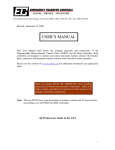
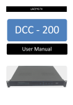
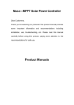
YG200 SWING GATE OPENER
OWNER’S MANUAL
©2005
Gatekeeper Ltd.
P.O. Box 752
Laceys Spring, AL 35754
http://www.gatekeeperltd.com
OUTLINE
1. Safety Precautions
2. Features
3. Specifications
4. Necessary Tools
5. Site Preparation
6. Mechanical Installation
7. Electrical Installation
8. Operation
9. Trouble Shooting
10. Warranty
IMPORTANT SAFTEY INFORMATION
Installing the YG200 Gate Opener requires the installation of
standard 110V electrical wiring. This work should only be
performed by a trained technician. Miswiring could cause
personal injury or DEATH. To prevent the risk of electrocution, be sure to turn
off all power to the YG200 until installation is complete. Read the the entire
user’s manual before beginning installation, and carefully obey the following
instructions:
• The Gate Opener should be installed by a qualified technician.
Otherwise, serious personal injury or property damage may occur.
• Before installation, all the locks of the gate should be unlocked.
• The auto-reverse function must be checked during installation to
ensure that the gate can auto-reverse in the event of obstruction.
• This auto-reverse function should be regularly inspected and adjusted,
if necessary.
• When opening or closing the gate, do not attempt to walk or drive
through the gate. Do not touch the gate while in operation.
• Children should not be allowed to play near or operate automatic gates.
• The maximum force that the gate opener can provide is 1500N.
• An electric lock is provided for installation for gate lengths greater than
5 feet (1.5 meters).
• IMPORTANT: Before installing, verify that the force adjust knobs inside
the control box for each motor are in the low position, and only advance
it towards additional force as required. See section Adjustment of the
Auto-Reverse Function
• This unit uses a current feedback system to stop. Do not operate the
opener without a solid stop block in place. This could cause injury,
damage to the opener or other personal property.
• Do not install the gate too close to the limit of travel; install the stop
block with at least three inches margin.
• The automatic gate opener must be grounded.
• Do not attempt to go through the gate while it is still in motion.
• This operator is intended for vehicular use only.
• Be careful when in close proximity to moving parts where hands or
fingers could be pinched.
• Additional safety equipment such as photoelectric sensors, safety
edges, roller guards and warning signs must be installed to prevent
injury.
• Do not allow control devices to be placed so that a person can access
them by reaching through the gate.
• In the event of power failure, an emergency release key allows you to
operate the gate manually.
• The opener should be switched off before repairing it or opening its
cover.
• Please erase and reset the code after installing the opener.
Class I: A vehicular gate opener (or system) intended solely for use in a
single-family home, or an associated garage or parking area.
ADDITIONAL FEATURES
•
•
•
•
•
•
•
•
•
•
•
•
•
•
•
•
Supports gate leafs up to 440 lbs or 8.2 feet
Keypad interface.
Single button interface.
Three position switch interface.
Infrared safety beam interface.
Supports up to 25 RF remotes, 2 included.
User programmable and user erasable remote codes.
RF rolling code technology prevents thieves from guessing your remote
code.
Auto-close feature is available for this opener.
Solid steel lock.
Push to open or pull to open configurable
Opening and closing position is automatically learned by the operator,
no need to program it.
Aluminum and cast metal housing.
For your safety, the YG-200 will stop and reverse if it encounters an
obstruction on opening and stop when it encounters an obstruction on
closing, as required by UL-325 safety standards.
Manual key release design for emergency purposes
Self-locking at any position
Specifications
Power Supply
AC 110V±10%V, 60Hz
Motor Speed
1680 rpm
Motor Output
Electronic lock Output
AC110V, 150W
DC12V 2A
Relay coil voltage
DC12V
MCU voltage
Remote control range:
DC5V
30m, Hopping Code
Control Box Weight
2Kg
Control Box Dimension:
276 mm (L) x 211 mm (W) x 112mm(H)
Environment temperature
10°C~+40°C
Auto Close Timer:
30 ± 3 seconds
Opening Time
<26 seconds
Working Angle of Gate
90° or 105°
Max. Gate Section Weight
440 lbs. (200kg)
Max. Gate Section Width
8.2 feet (2.5 meters)
Duty Cycle
25%
Noise
<65dB(A)
Emergency Release Key in Case of Power Failure
Class I: A vehicular gate opener (or system) intended solely for use in a
single-family home, or an associated garage or parking area.
Necessary Tools and Equipment
The following tools may be necessary to install the YG-200 opener. You will
need standard and Phillips screw drivers, an electric drill, wire cutters and a
wire stripper, a socket set, and possibly access to a welder if your installation
cannot use the supplied brackets. If the brackets shipped do not fit your gate
because of the dimensions of your gate, you may also need equipment to cut
and grind metal parts. In some rare cases you may have to fabricate brackets
for your application or notch a column in order to obtain the necessary set
back.
Site Preparation
Before you begin the opener installation, the gate should be mounted to the
mounting posts and swinging freely, there should be little resistance in the
swing of the gate. The gate and post must be suitable for being automated.
Check that the structure is sufficiently strong and rigid, and that its dimensions
and weights conform to those listed in the specifications table of this
document. Make sure that the gate is plumb and level. The fence posts must
be mounted in concrete. Since both motors must be powered, a set of wires
from the control box to both motors will be required. Therefore it is necessary
to dig a shallow trench across the driveway. If the driveway is paved this will
require a masonry saw and chisel. The YG-200 is powered by 110V/60Hz AC
power, therefore if you have not already done so; wire a waterproof outlet
near the gate following proper safety standards for your area. If you are not
experienced with this type of wiring or if your area requires it, hire a
professional electrician to perform this as well as wire in the YG-200 in the
electrical section. The YG-200 requires at least a 10A service. Make sure
your electrician takes into account the voltage drop involved in running many
feet of wire to your installation location. If an insufficient gauge of wire is
used, there will be insufficient power at the site to operate the opener. Once
the gate is mounted adequately, electrical power is available, and a trench for
the control motors is dug, you are ready to proceed.
Parts List
1
Hood pipe
22
24T ring gear
2
End joint
23
Locating shield
3
Pin 10x40
24
Motor
4
Steel tube
25
Capacitor bracket
5
Small support ring
26
Capacitor
6
Right housing
27
Wiring base
7
Screw M5x20
28
Wiring terminal
Locknut
29
Screw M4x8
8
Screw shaft
30
Wiring cover
9
Connect socket
31
Tapping screw
9A
Split ring
32
Joint block
10
Tapping screw
33
Axle pin
11
Outer tube
34
Earth wire
12
Large support ring
35
Release key
13
Bearing 6004
36
Lock
14
Pin 8x35
37
Seal 17X2.65
15
27T ring gear
38
Upper cover
16
Planetary gear
39
Screw 4.2x9.5
17
Central gear
40
Waterproof seal
18
Pin 4x20
41
Hexagonal nut
19
Seal 13.2x2.65
42
Light housing
20
Square gasket
43
Waterproof seal
21
Spring
7A
Parts Diagram
7
6
25
26
5
27
28
29
4
3
30
2
31
24
32
23
33
22
34
21
1
20
18
17
15
19
43
16
14
13
12
11
42
41
10
9A
9
8
7A
40
39
38
37
36
35
Mechanical Installation
Begin with both openers unlocked. Next identify if this will be a “push to open”
or a “pull to open” installation. In either configuration, the gate is mounted on
one face of the mounting post, and the opener is mounted on the face 90
degrees from it. Below are schematics of both “push to open” and “pull to
open” configurations.
Fig. 1
Fig. 2
R eta iner
lo se p ositio n)
G a te op en er
E n la rge
R etaine r
(o pe n po sition )
The installation should meet the specifications shown in figure 3. See Fig. 3.
Fig. 3
Retainer
(close position)
110
A
140
130
B
125
115
Cmax
50
50
¦Á
90¡ ã
105¡ ã
A
B
Á
1020
¦
Gate opener
Cmax
Enlarge
Retainer
(open position)
>0¡ ã
Main Structure
Fig. 4
Special motor
Planetary reducer
Screw shaft
Control box
The installation height range is 1.18 – 3.15 inches (300 – 800mm). See Fig.
5. If the opener is mounted at a height above the specified range, and the
gate is not sturdy enough, then it may result in bending or damage to the gate
and or gate opener.
Fig. 5
Gate pillar
Gate opener
Gate
Electric lock
Gate Geometry
In order to obtain the desired opening angle, proper gate geometry is
essential. This is also sometimes called setback. The opener must be able to
swing from the closed position to the open position (touching the stop block)
while not extending to within 3 inches of its maximum travel. This may involve
notching the column, which is cutting into the column in order to bring the
opener nearer to the gate hinge. Another alternative to notching the column is
manipulating the shape and length of the brackets used to mount the gate to
the post, the actuator to the post, and the actuator to the gate. These
brackets are labeled A, B, and D, respectively. With these bracket lengths
known, the opening angle and G, the position along the gate which the D
bracket is welded can be calculated. Of course many installers accomplish
this by trial and error, but it can be calculated directly, and an online calculator
is available on the Gatekeeper site at:
www.gatekeeperltd.com/calc/calcgate.php
Most users will not be able to vary the size of the bracket A, the bracket
holding the gate to the post. It is also relatively impractical to vary the bracket
D, the bracket which holds the actuator to the gate. Therefore the most
common and straightforward way to proceed is to vary the value of B until the
calculator provides the proper value for the opening angle. Always verify that
the required 3 inches of margin mentioned above is preserved when checking
these measurements.
Positive Stop Block Installation
The YG-200 Automatic Gate Opener uses a current feedback system to
detect its stopping / reversing point. The control box supplies an electrical
current to the actuator motors to move the gate. As resistance increases, for
instance hitting an obstacle or the stop block, the current required to continue
operating the actuator motor increases. The control box constantly compares
the required current with the position of the force adjustment knob. If the
required current is greater than the position of the force adjustment knob, then
the opener will stop. If the actuator has not traveled a significant portion of its
available travel during closing, when it detects this high current condition, it
will sound the alarm and perform an emergency stop and auto reverse. If this
condition is detected during opening instead of closing, it will perform an
emergency stop. If an emergency stop condition occurs, terminate power
to the unit, use the keys to unlock both actuators, and move them to the
closed (actuators retracted) position before re-enabling power to the
unit. Failure to do so could cause damage to the opener or gate.
Therefore, the YG-200 absolutely requires a solid stop block. The stop block
(supplied in the YG-200 kit) should be placed such that it stops the actuator
arm at least 3 inches before it reaches its maximum travel. This margin is
required to prevent the actuator arm from over-extending before the control
box can shut down power to it. After mounting the actuator arm, with the key
unlocked, verify that it stops at the proper position.
The gate geometry must be manipulated until the gate can be moved
from the closed to the open position with the desired opening angle and
without reaching within 3 inches from the end of travel before hitting the
stop block. You are not ready to proceed to powering the actuator arms
or mounting the control box until this step is accomplished!
Front and Rear Parts of Gate Opener
To install the rear part of the gate opener, insert shoulder screw and spacer,
then tighten with the nut. See Fig. 6.
Fig. 6
S h o u ld e r s c re w
R e a r p a rt o f
g a te o p e n e r
S u p p o rt b ra c k e t
S pacer
Nut
To install the front part, fit the hole in the front part with the hole in the
supporting plate, and push the axle pin into the holes (using hands or a
hammer), and finally fit the retainer clip. See Fig. 7.
Fig. 7
Supporting plate
Axle pin
Front part of gate opener
Retainer clip
Wiring of the gate actuators
Screw off the two stainless tapping screws, and then remove the cover and
wiring as shown in Fig. 8. WARNING: Follow the wiring diagram precisely.
Failure to do so could cause damage to the gate opener controller. Gauge
16-3 wire is sufficient for wiring the gate motors.
Fig. 8
Stainless tapping screw
M
U V W
Upper cover
Enlarge
Hood Shield
Install the hood pipe, tighten the screws into the opener and cover the hood
shield over the joint. See Fig. 9.
Fig. 9
M a in u n it
H o o d p ip e
Ho o d p i p e
S cew
H o o d s h ie ld
Waterproof caps
There are 8 caps in total – 4 to be used and 4 spares. When the gate opener
is installed, the caps are used to cover the upper holes of the unit to avoid
leakage. See Fig. 10.
Fig. 10
W a te rp ro o f c a p
G a te o p e n e r
Retainer – Closed and Opened Positions
Close the gate section to its fully closed position; fix the retainer according to
the position of the gate section. NOTE: Each section is completed
separately. See Fig. 3.
If the maximum angle for installing is 105°, the retainer should be installed on
the ground at approx. 100°. If the installing angle is 90°, the retainer should
be installed at 90°. See Fig. 3.
Electric Lock
If the gate section is >5 feet (1.5 meters), it is recommended that you install
the electric lock. Weld the steel plate of the lock to the gate, and then fix the
lock. See Fig. 11 to determine the height of the plate.
Fig. 11
A
Release here
Electric lock
Base plate
To install the base plate of the lock, fix the plate to the ground with 3 screws
and make sure that the lock pin can fit tightly in the hole in the plate.
Adjustment
The pair of gate sections will not start simultaneously. The gate section
without the lock will start to open earlier than the other gate section, so that
both sections can be locked properly. A plate or tab can be welded on the
gate section with the lock so that when it closes, it will trap the gate section
without the lock between itself and the center stop block, thus locking both
gate sections.
Mechanical Maintenance
• Check the screw lubricant and add #1 grease regularly to both gate
actuators.
• Regularly verify that the gate swings freely and add grease as directed by
the manufacturer of the gate.
• Keep opener clean at all times.
Electrical and Control Box Installation
1. Please Review the following Safety instructions before installation
Please read user’s manual carefully and obey the following:
! It should be installed by a qualified technician. Otherwise serious personal injury or
property damage may occur.
! Before installation, all the locks of the gate should be unlocked.
! The auto-reverse function must be checked during installation to ensure that the gate
can auto-reverse in event of obstruction.
! This auto-reverse function should be regularly inspected and adjusted, if necessary.
! When opening or closing the gate, do not attempt to walk or drive through the gate.
! Do not touch the gate while it is in operation.
! Please switch off before repairing it or opening its cover.
! Please erase and reset the code after installing the operator.
! Before powering up the opener for the first time, verify that the force
adjustment knobs are in a low position (turned towards counter clockwise
direction) until the force adjustment is set in that section.
2. Installation
(1) Install the cable
!
In order to protect the wires, between the gate operator and the control box, armored
cable, galvanized cable or PVC pipe must be set into the concrete when it is poured.
Wires within the cable shall be located or protected so that no damage can result
from contact with any rough or sharp part. The diameter of the cable should be more
than 20mm2; the diameter of wire inside the cable should be more than 1.0mm2.
Gauge 16-3 wire or better is sufficient to wire the control box and the gate actuators.
(2) Install the control box
!
The control box circuit should be equipped with single-phase breaker (10A).
!
Make sure that power is OFF before making any electrical connections.
!
Open the cover of the control box, remove the control board, and fix the control box
on the wall. See Fig. E-1
!
Perform the wiring and replace the cover. (See table 2 and Fig. E-3)
Note: (1) we regard the gate with the electrical lock as No.1 gate, the other gate as No.2
gate. (2) If you want to use auto-close function, the gate operator must be equipped with
the infrared device.
Fig. E-1 mounting size
Table 2 wiring between control box and gate operator
Position
Tab
Remark
21(Terminal X12)
L
Connect live wire
21(Terminal X12)
N
Connect neutral wire
21(Terminal X12)
E
Connect ground wire
19 (Terminal X11)
U1
Connect No.1 motor COM/U
19 (Terminal X11)
V1
Connect No.1 motor V
19 (Terminal X11)
W1
Connect No.1 motor W
19 (Terminal X11)
C1, C1
18(Terminal X10)
U2
Connect No.2 motor COM/U
18(Terminal X10)
V2
Connect No.2 motor V
18(Terminal X10)
W2
Connect No.2 motor W
18(Terminal X10)
C2, C2
Connect No.2 motor capacitor
17(Terminal X9)
LAMP
Connect alarm lamp
16(Terminal X8)
LOCK
Connect electronic lock
Connect No.1 motor capacitor
(3) Install the External Keypad/Button Switch
The YG-200 is equipped with an interface for an external switch or keypad. The
interface type is a NO (Normally Open) momentary switch to ground. To activate the
opener, the keypad or other device must short the ground and the appropriate terminal
momentarily. This type of switch is very common. To install the keypad attach one
lead of your keypad to the O/S/C terminal and the other to the GND terminal. The
keypad will function in single channel mode just like the RF remote. For three button
switch installation, use the terminals for multi-channel mode. Three-button mode: The
port ‘GND’ is the common port, the port ‘OP’ is used to open the gate, ‘CL’ is used to
close the gate, and ‘ST’ is used to stop the gate. Single-button mode: connect two
wires of button switch to ‘O/S/C’ (see Fig.E-3 terminal X7 No.15) of control board.
Safe guard (Infrared device)
If the infrared beam is broken during closing, the gates will reverse and open
immediately. During opening, the beeper will ring. The control box is not
factory equipped with an infrared device.
Connect signal wire of infrared device to ‘IR’ (see Fig. E-3 terminal X6, No.14),
connect common wire (i.e. ‘power supply –‘) of infrared device to ‘GND’
(terminal X6, No.14), and connect ‘power supply +’ of infrared device to ‘12V’
(terminal X6, No.14).
The infrared device can be obtained through your dealer. To find a dealer in North
American, go to www.gatekeeperltd.com/dealers
3. RF Remote
Button 1
Button 4
Button 2
Button 3
Fig. E-2
(1) Learn / erase remote controls
Verify that the force adjustments knobs are in the low position before proceeding.
Adding extra remote controls (Learn): Press red button on the control board (see Fig.
E-3 No.12), then the ‘LED’ (see Fig. E-3 No.11) will be on, it will turn off when you press
any remote control button. Press the same button, the ‘LED’ will flash at 2Hz frequency
and then turn off; this indicates the learning process is finished. If it fails to set, the ‘LED’
will turn off automatically after flashing for 1 second, you should follow the steps above to
reset.
Up to 25 remote controls may be used.
To erase all remote controls: press and hold the red button on the control board until
‘LED’ turns on and then turns off. This indicates that all the remote controls have been
erased completely. You should reprogram the remote control if you want to control this
operator (see Adding extra remote controls section).
(2) The remote control works in a single channel mode. It has four buttons. See Fig. E-2.
With each press of the remote control button which has been programmed, the gate will
close, stop, open or stop cycle.
Warning: Notify the users that the gate is never to be operated unless it is in full view.
Additional RF Remote controls can be obtained through your dealer. To find a dealer in
North American, go to www.gatekeeperltd.com/dealers
4. Operation of the gates
The gates can be controlled by using remote control, single-button mode or three-button
mode external button switch.
!
Unlock the gate opener with the key. Push the gates to the opened (retracted)
position manually. Lock the gate opener with the key.
!
Turn the power on.
!
Close the gates by using the remote control, single-button mode or three-button
mode external button switch. The No.2 gate-leaf will close first, and then the No.1
gate-leaf with lock will close after 3 seconds.
!
The gates will stop at the closed position automatically, or you can stop the gates at
the closed position by remote control, single-button mode or three-button mode
external button switch. If gates do not stop or bind before stopping, verify that the
stop is firmly in place, and the force adjustment knob for that gate on the control
board is adjusted correctly. Adjust counter-clockwise to reduce binding.
!
Open the gates by remote control, single-button mode or three-button mode external
button switch. First, the electrical lock will be opened, the No.1 gate-leaf with lock
will open, and then the No.2 gate-leaf will open after 3 seconds.
!
The gates will stop at the opened position automatically, or you can stop the gates at
the opened position by remote control, single-button mode or three-button mode
external button switch. If gates do not stop or bind before stopping, verify that the
stop is firmly in place, and the force adjustment knob for that gate on the control
board is adjusted correctly. Adjust counter-clockwise to reduce binding.
!
Total working time: 21 seconds.
Note: The gate will return to open if you press the ‘OPEN’ button on the three-button
mode external button switch during closing, the beeper will ring. We call this Open
priority.
Auto-reverse function
It is very important that you tune the safety reverse function on your gate
opener. Power the control box if it is not already and verify that you have
completed the remote programming exercise. When properly adjusted, the
gate should close and stop when it hits the stop block without overly forcing
the gate, and reverse if it strikes an object before it reaches its stop. An alarm
should sound if it activates the auto reverse. Use a screw driver to rotate the
Force Adj. knob. Rotating clockwise will increase the resistance needed to
trip the safety reverse function. Rotating counter-clockwise will decrease the
resistance. If the gate does not move when activated, or auto reverses
without striking an obstacle, then the resistance setting may be too little. If the
gate does not stop when an obstruction is placed in its path, then the setting
may be too high. Start with just above the minimum value, and tune it to use
the minimum setting for which the gate will function.
WARNING: Do not attempt to tune the gate by placing your hand, arm or
other body part in the path of the gate, serious injury could result. Also
placing a heavy immovable object in the path to test with could cause damage
to the gate opener motors. Instead, place a light object in the path, preferably
something like a chair or trash can which will be pushed out of the way if the
setting is still too high without causing damage to the gate motors. Note, this
auto reverse function should be regularly inspected and adjusted if
necessary. Once this step is complete replace the cover and install the
rubber caps over the screws.
Auto-close function
Turn the fourth dip-switch (See Fig. E-3 No.13) to the ON position; the gates
will stay open for 30 ± 3 seconds before automatically closing. Factory preset:
the fourth dip-switch is in the OFF position, i.e. the auto-close function is shut
off. An Infrared device is required to be installed for safety if the auto-close
feature is enabled.
Safe guard (Infrared device)
If the infrared beam is broken during closing, the gates will reverse and open
immediately.
During opening, the beeper will ring. The control box is not factory equipped
with an infrared device.
The infrared device can be obtained through your dealer. To find a dealer in
North American, go to www.gatekeeperltd.com/dealers
Fig. E-3 Control board
Table 3 wiring notes of control board
Position
Function
Remark
1
Transformer input
AC110V
2
Transformer output
AC12V
3
Fuse
5 x 20 2A
4
Force adjustor (for No.1 gate-leaf
with electrical lock)
The resistance may be increased or decreased
by rotating clockwise or anticlockwise.
5
Force adjustor (for No.2 gate-leaf)
The resistance may be increased or decreased
by rotating clockwise or anticlockwise.
6
Beeper
12V
7
Antenna
Impedance: 50Ω
8
Receiver panel
Receive signals
9
Memory card
It can be unplugged; it is used to store signals.
10
Power indicator light (LED1)
1206 green
11
Indicator light (LED)
1206 red
12
Learn button
6 x 6 red
13
Dip-switch
Set auto-close function
14
External device interface
Connect infrared device
15
External button switch interface
Connect external button switch
16
Electrical lock interface
DC12V
17
Alarm lamp interface
AC110V
18
Motor and Capacitor interface
Connect No 2 motor
19
Motor and Capacitor interface
Connect No 1 motor
20
Fuse
5 x 20 10A
21
Power supply
AC110V 60Hz
Table 4 Troubleshooting
Symptoms
Gate will not open or
close
Possible cause
Remedy
(1) Power is OFF.
(1) Make sure that power is ON.
(2) The gate is
obstructed.
(2) Remove obstructions.
(3) Force Adj. Is set too
low.
(3) Rotate force adjustment knob
clockwise
Gate fails to reverse.
(1) The ‘FORCE ADJ’ is
adjusted too high.
(1) Adjust ‘FORCE ADJ’ counterclockwise to decrease force.
Gate begins to close,
then reverses.
(1) The ‘FORCE ADJ’ is
adjusted too low.
(1) Adjust ‘FORCE ADJ’ clockwise to
increase force.
(2) The gate is
obstructed.
(2) Remove obstructions.
(1) The indicator light of
remote control does not
light.
(1) Battery level may be low, replace
the battery inside the remote control.
Remote control does
not work
(2) Remote control is
not suitable for receiver.
(2) After making sure the codes are
correct, erase remote controls and
then re-program the remote control.
(3) Receiver panel.
(3) Check the receiver panel; make
sure it is plugged in at the control
board.
Gate running
direction is not
correct, or gates run
in different directions.
(1) Wiring is incorrect.
(1) Please change wires “V1 and
W1”or “V2 and W2”. If the wiring
between two gates is wrong and the
gates cannot work, please check the
wiring between “U1, V1, W1”and “U2,
V2, W2”.
Gate does not stop
when it should or
closes too hard
(1) The ‘FORCE ADJ’ is
adjusted too high.
(1) Adjust ‘FORCE ADJ’ anticlockwise
to decrease force.
(2) Positive stops are
not installed properly or
are installed too far from
the opener’s limit of
travel.
(2) Install positive stops as described
in the mechanical positive stop
installation section of this manual or
move stop in closer to the opener’s
limit of travel.
Gate does not open
far enough or does
not have the proper
opening angle
The gate opener is not
installed properly
according to fig. 3 in the
gate geometry section
of this manual.
Either modify the installation to meet
fig. 3 or adjust the size or replace the
installation brackets in accordance
with the gate geometry section of this
manual.
Gatekeeper Ltd. Limited Warranty
Gatekeeper Ltd. warrants the YG-200 Swinging Gate Opener to be free of
defects in materials and workmanship for a period of 1 year from the date of
purchase subject to certain limitations.
This warranty shall not apply in the following circumstances, misuse,
vandalism, accident, neglect, unauthorized repair or modification, acts of God
(lightning, flood, insect damage etc.), power surge, corrosive environments,
incorrect installation or application, damage to mechanism due to wrong type
of gate, incorrect weight, gate not operating freely or not on level ground etc.
The warranty set forth here shall be entirely exclusive and no other warranty,
either written or oral is expressed or implied. Gatekeeper Ltd specifically
disclaims any and all implied warranties of merchantability or fitness for a
particular purpose. It is the purchaser’s sole and exclusive responsibility to
determine whether or not the equipment will be suitable for a particular
purpose. In no event shall Gatekeeper Ltd be held liable for direct, indirect,
incidental, special, or consequential damages or loss of profits whether based
on contract, tort, or any other legal theory during the course of the warranty or
at any time thereafter. The installer, purchaser and/or end user do agree to
assume all responsibility for all liability in use of this product, releasing
Gatekeeper Ltd of all liability.
For service under this warranty, please contact your dealer. All parts,
accessories, service and support for Gatekeeper products is supplied through
our network of dealers. Dealer information can be obtained at
www.gatekeeperltd.com/dealers
** Special Warranty Note:
Improper installation of the YG-200 can cause the actuator arms to overrun
and unscrew into two parts. This can sometimes cause damage to parts 9 or
10. Carefully read and apply the directions in this manual to prevent this.
However if this condition does occur, do not panic. The operator can be
easily reassembled by inserting part 4 into the rest of the assembly and
rotating clockwise. Since this condition is due to improper installation, this will
not be considered an in warranty repair. However if any parts were damaged
due to this condition, parts can be obtained from your dealer. To find a dealer
visit: www.gatekeeperltd.com/dealers
Gatekeeper Ltd.
P.O. Box 752
Laceys Spring, AL 35754
[email protected]
For updated versions of the manual see:
http://www.gatekeeperltd.com
For Additional Remotes, Infrared Photo Cells or
Parts please contact your dealer. To locate a
dealer, please visit us at:
www.gatekeeperltd.com/dealers