1
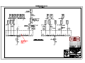
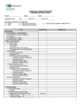
CITY OF TACOMA
Department of Public Utilities – Tacoma Power
ADDENDUM NO. 2
DATE: October 5, 2015
REVISIONS TO:
Request for Proposals Specification No. PG15-0519F
Tacoma Power Warehouse Community Solar
REVISIONS TO THE SUBMITTAL DEADLINE:
The submittal deadline remains the same, Tuesday, October 13, 2015.
REVISIONS TO THE TECHNICAL PROVISIONS:
Replace Section 16000 – Solar Panel System with revised Section: clarified PV System
responsibilities and revised transformer requirements.
REVISIONS TO THE EXHIBITS:
Replace Exhibit A Tacoma Power Site Survey Appendix F Drawing No. PP6003 with revised
drawing: clarified tie-in point for Phase 1 and Phase 2.
Insert Exhibit A Tacoma Power Site Survey Appendix I Drawing No. PP3574 – Warehouse
South (Upper) Roof PVC Membrane Installation drawing: provide roof membrane installation
details.
NOTE: Acknowledge receipt of this addendum by initialing the corresponding space as
indicated on the Signature Page. Vendors who have already submitted their bid/proposal may
contact the Purchasing Division at 253-502-8468 and request return of their bid/proposal for
acknowledgment and re-submittal. Or, a letter acknowledging receipt of this addendum may be
submitted in an envelope marked Request for Proposals Specification No. PG15-0519F
Addendum No. 2. The City reserves the right to reject any and all bids, including, in certain
circumstances, for failure to appropriately acknowledge this addendum.
Patsy Best, Procurement and Payables Manager
Finance/Purchasing Division
cc:
R. McLaughlin, Project Manager, Generation
T. Ryan, Generation Assistant Manager, Generation
Form No. SPEC-220A
Revised: 08/10/2011
SECTION 16000 – SOLAR PANEL SYSTEM
PART 1 GENERAL
1.1
SECTION INCLUDES
This specification establishes the system components, design, installation, and
commissioning required of the solar panel system. The Respondent shall design,
procure, install and commission a complete system consisting of the components and
requirements of this section and Tacoma Power Photovoltaic Site Survey (see Exhibit A
of this RFP).
1.2
REFERENCES
A. REFENCES
This section contains references to the following documents. They are a part of this
section as specified and modified. Where a referenced document contains references to
other standards, those documents are included as references under this section as if
referenced directly. In the event of a conflict between requirements of this section and
those in the listed documents, the requirements of this section shall prevail.
Unless otherwise specified, references to documents shall mean the documents in effect
at the time of the advertisement of the RFP. If reference documents have been
discontinued by the issuing organization, references to those documents shall mean the
replacement documents issued or otherwise identified by that organization or, if there are
no replacement documents, the last version of the document before it was discontinued.
1. ANSI C2
National Electric Code
2. NFPA 70B
Electrical Equipment Maintenance
3. NFPA 70
National Electric Code (NEC)
4. NECA 1
National Electrical Respondents Association – Standard Practices for
Good Workmanship in Electrical Contracting
5. IBC
1.3
International Building Code
SUBMITTALS
A. The Respondent shall submit the following in accordance with Construction Special
Provisions Section 01300 – Submittals
B. SYSTEM DESIGN
Respondent shall submit the following design documents prior to procurement of
materials:
1. Detailed Site Diagram showing:
a. Elevation and plan view of PV array location and/or 3-D rendering.
b. Plan and Elevation and plan view of all new electrical equipment to include but
not limited to inverters, disconnects, power panels, transformers, and metering
equipment.
2. Electrical Single-line diagram - Must include all information about major system
components specifications and ratings, conductor size and type, conduit size, ratings
of AC combiner power panels and OCPD’s, transformer ratings, and type and ratings
of facility electrical panel interconnection point.
Construction Special Provisions - Section 16000
Request for Proposal PG15-0519F
Page 1
3. Wire Sizing Calculations – Ampacities of conductors shall be determined using NEC
tables. Voltage drops for PV source, output and inverter output circuits shall be
determined by calculations and limited to manufacturer recommendations or
tolerances. All calculations shall be submitted to Tacoma Power for review.
4. PV Array Racking — The Respondent will be responsible for generating the PV array
racking design and attachment methodology. Respondent shall provide this
information to Tacoma Power in a timely manner for approval, prior to obtaining the
building permit.
5. Field Verification — Respondent must field verify design feasibility and/or all record
documents and prepare own as-builts prior to submitting final design for approval in
order to ensure proper system installation, successful integration with existing
systems, and adherence to contract timeline.
C. CONSTRUCTION SUBMITTALS
The Respondent shall supply all appropriate manufacturers’ data on the following. All
specifications, cutsheets, and product data shall be marked to identify the specific
products, models, options, tolerances, dimensions, and other pertinent data.
1. ITek Energy HE Solar Panel Data Sheet and Panel Layout Plan.
2. Solectric PVI TL Inverter and Data Sheet, Installation Manual, and Installation
Locations Plan.
3. PanelClaw Polar Bear III Racking and Anchoring Brochure, Installation Manual,
Installation Layout Plan, Rack/Anchoring Details, Stamped Rack/Anchoring
Calculations.
4. Sika Sarnafil Warranty.
5. DECK Monitoring Project quote, datasheet, installation and user manual.
6. AC Combiner Panel and OCPD’s specifications, panel layout, breaker sizes, and bus
size and layout.
7. Production meter base data sheet.
8. Step-up transformer data sheet.
9. Operation and maintenance manuals for equipment supplied. Three (3) hard copies
and two (2) compact disks (CD’s) shall be required.
10. DC and AC wiring, raceways, enclosures, components, fittings and fasteners.
1.4
CODE REQUIREMENTS AND UTILITIES
A. For questions regarding permitting, contact Tacoma Power electrical permitting
department.
1.5
PERMITS AND FEES
A. The Respondent shall apply for all necessary permits, licenses, and approvals
required for the execution of this work in accordance with Construction Special
Provisions Section 01040 – Project Coordination, Paragraph 1.3 - Permits.
B. The Respondent shall apply for and obtain a no fee electrical permit through Tacoma
Power’s New Services and Electrical Inspection Division. A plan review of the
proposed electrical system will be required.
C. The Respondent shall arrange for inspection of work by the inspectors and shall give
the inspectors all necessary assistance in their inspection of work.
Construction Special Provisions - Section 16000
Request for Proposal PG15-0519F
Page 2
1.6
TEMPORARY POWER
A. Coordinate with Tacoma Power for temporary power, if required.
1.7
COORDINATION
A. The Respondent shall coordinate and sequence work to prevent interferences,
conflicts, and sequence of construction.
B. Any discrepancies between the electrical equipment and other equipment shall be
brought to the immediate attention of Mr. Greg Kenyon, at 253-441-4467.
C. Coordinate equipment mounting locations and heights with existing structure and
surrounding finishes.
1.8
DELIVERY, STORAGE, AND HANDLING
The materials shall be protected from damage following delivery and shall be handled
and storage in accordance with all manufacturer’s instructions.
1.9
PROJECT WARRANTY
A. Respondent shall provide a five (5) year workmanship warranty
B. Respondent shall provide a five (5) year manufacturer’s warranty on all system
components except inverters which shall have a ten (10) year manufacturer’s
warranty.
C. Respondent shall provide a roofing warranty through May 15, 2033, as outlined in
Paragraph 4.5 of this section.
PART 2 SYSTEM DESIGN
2.1
TACOMA POWER PV SYSTEM DESCRIPTION
The following provides a general description of the overall project and the associated
system components as necessary for the development of the final design drawings and
calculations:
A. The installation for the solar panels will be located at the Tacoma Power Warehouse,
3628 South 35th Street, Tacoma, WA 98409 and will include either Phase 1 or
Phase 1 and 2 solar system “projects” (phases) of 74.48 kW each.
B. Tacoma Power Photovoltaic Site Survey: A Photovoltaic Site Survey and associated
document appendices, dated August 24, 2015 (see Exhibit A of this RFP) has been
drafted by the Bonneville Environmental Foundation. In addition to this section, the
Photovoltaic Site Survey document provides additional project site overview, facility
overview, and proposed equipment.
C. The Respondent is responsible for design, engineering, permitting and
construction of the solar system as described in this RFP. The City is
responsible for engineering as it pertains to the evaluation of the existing
building structure. The City has determined the solar system shall be limited
to 4.25 psf. Any building structural upgrades required or costs incurred due to
the system exceeding the system 4.25 psf weight will be the responsibility of
the Contractor.
2.2
INTERCONNECTION REQUIREMENTS
1. Recommend grid connected via a Step-up transformer to a breaker landed in a
480/277v, 3 phase, 4 wire, 1200A 800A switch board, labeled “1MD”.
2. Production meter base to be provided by contractor. Revenue grade meter to be
provided by Tacoma Power.
Construction Special Provisions - Section 16000
Request for Proposal PG15-0519F
Page 3
Contractor to arrange meter installation through TP’s electrical inpection division.
3. PV inverter outputs to land in AC combining electrical panel, SquareD, no equal
4. External PV energy production meter to be located on the building’s west exterior
next to inverters.
5. Tacoma Power approved placards identifying the location of the PV system
disconnect will be required at the existing building service/meter location.
PART 3 PRODUCTS
3.1
1.
TACOMA POWER PV SYSTEM COMPONENTS
Mounting system
a. PanelClaw Polar Bear Gen III
b. Tilt: 10º
c. Orientation: to match roof at 180º south.
d. Respondent to specify proposed racking layout in bid response with a drawing.
2.
PV Modules
a. (Quantity: 266 modules per project) Itek Energy IT-280 HE.
b. Made in Washington panels required.
c. Grade B panels will be accepted provided that defects are purely
cosmetic and do not cause any loss of production. Warranty shall be the
same as non-Grade B panels. The city reserves the right to reject any
Grade B panel that has excessive cosmetic defects.
3.
Inverters
a. Made in Washington, Solectria PVI TL series, grid-tied string inverters.
b. Located on the west exterior wall.
c. Inverter outputs combined with dedicated solar AC combiner panel.
4.
Electrical Panels: Square D, 1x PV system AC combining electrical panel to allow
aggregate interconnection of the entire PV system to existing electrical panel.
a. Located on the west exterior wall
5.
DECK Monitoring System
a. Made in Washington, Solectria PVI TL series, grid-tied string inverters
b. Located on the west exterior wall
c. Inverter outputs combined with dedicated solar AC combiner panel
6.
Step up Transformer: Step up transformer to accommodate 480/277V
interconnection. Transformer: Shall be dry-type, all copper windings relocated
within 12-feet of 1MD panel and be one (1) of the following configurations:
a. 208Y / 480Y step-up transformer.
b. 208Y / 480Y Delta step-up transformer.
c. 480 Delta / 208 Y step-down transformer (reverse fed)
7.
Production Meter: 1x PV system production meter base to provide aggregate
energy production metering of entire PV system, located after AC combiner panel.
Construction Special Provisions - Section 16000
Request for Proposal PG15-0519F
Page 4
8.
DC and AC wiring, raceways, enclosures, components, fittings and fasteners: as
designed and in compliance with NEC, local building department, and utility
interconnect requirements.
9.
DECK Monitoring System:
a. Respondent will be required to install all necessary data communication
components required by the DECK monitoring, inverter direct commercial
monitoring system.
b. Projected pre-assembled DECK hardware components include:
1) NEMA 4 Enclosure
2) Acquisuite Data Logger
3) Internal 120v Power Supply
4) Two (2) Surge Suppressors
5) 3-foot Ethernet Cable
10.
Inverter direct communications wiring (shielded Cat5) to the DECK equipment will
be provided by the Respondent.
PART 4 EXECUTION
4.1
MATERIAL PROCUREMENT
Respondent shall be responsible for procuring all system materials per the City
approved contactor provided design drawings as necessary for a completely operational
solar panel system, whether or not specified in the system description, unless otherwise
indicated above that it will be supplied by Tacoma Power or others.
4.2
PV SYSTEM INSTALLATION
A.
Respondent shall be responsible for installing a grid-tied photovoltaic installation at
the Tacoma Power warehouse. The installation shall be compliant with the current
NEC and/or all applicable building codes and standards. It is the Contractor’s
responsibility to ensure code compliance with the local authorities. The installation
shall be executed according to the City approved system design documentation.
Tacoma Power must approve any design changes made in the field.
B.
Respondent will provide adequate protection of the roof membrane in accordance with
Sika Sarnafil requirements (see Exhibit B – Roofing Warranty of this RFP) during the
installation. This will include, but may not be limited to, landing pads, protective
barriers, balloon carts, and suitable housekeeping. No material will be permitted to be
stored on the roof membrane without a protective barrier. Respondent will be required
to attend a pre-installation walkthrough with a certified Sika-Sarnafil roof
inspector/contractor and will be responsible for any roof damage during the installation
process. The Respondent will pay for the pre and post installation roof inspections.
C.
Respondent will subcontract and oversee the roofing installation to a Sika Sarnafil
approved roofer and adhere to the Sika Corporation Photovoltaic
Installation/Warranty Policy (see Exhibit B of this RFP).
D.
Respondent will be responsible for roofing repairs at any and all roof penetrations
and mechanical attachments to the roof deck as required to re-establish the current
roofing warranty (see Exhibit B – Roofing Warranty of this RFP)..
E.
Respondent will be responsible the procurement and installation of any and all
ballast materials as determined by the racking respondent’s structural engineering.
Construction Special Provisions - Section 16000
Request for Proposal PG15-0519F
Page 5
F.
All electrical equipment, such as power panels, inverters, cable, and conduit shall
be installed according to the following procedures:
1.
Cable Installation
Except as otherwise specified or indicated, cable shall be installed according to the
following procedures, taking care to protect the cable and to avoid kinking the conductors,
cutting or puncturing the jacket, contamination by oil or grease, or any other damage.
Circuits to supply electric power and control to equipment and devices, communication
and signal circuits shall be installed continuous and may not be spliced unless approved
by the City.
a. Stranded conductor cable shall be terminated by lugs or pressure type connectors.
Wrapping stranded cables around screw type terminals is not acceptable.
b. Stranded conductor cable shall be spliced by crimp type connectors. Twist on
wire connectors may be used for splicing solid cable and for terminations at
lighting fixtures.
c. Splices, if approved, may be made only at readily accessible locations.
d. Cable shall not be pulled tight against bushings nor pressed heavily against
enclosures.
e. Cable pulling lubricant shall be compatible with all cable jackets; shall not contain
wax, grease, or silicone; and shall be Polywater "Type J".
f.
Where necessary to prevent heavy loading on cable connections, in vertical
risers, the cable shall be supported by Kellems, or equal, woven grips.
g. Spare cable ends shall be taped, coiled, and identified.
h. Cables shall not be bent to a radius less than the minimum recommended by the
manufacturer. For cables rated higher than 600 volts, the minimum radius shall
be 8 diameters for non-shielded cable and 12 diameters for shielded cable.
i.
2.
All cables in one conduit, over 1 foot long, or with any bends, shall be pulled in or
out simultaneously.
Conduit Installation
Contractor shall be responsible for routing all conduits. Contractor shall be responsible for
routing the conduit to meet the following installation requirements:
a. Conduit installed in all exposed indoor locations shall be rigid steel. Exposed
conduit shall be rigidly supported by hot-dip galvanized hardware and framing
materials, including nuts and bolts.
b. Final connections to dry type transformers, to motors without flexible cords, and
to other equipment with rotating or moving parts shall be liquidtight flexible metal
conduit with watertight connectors installed without sharp bends and in the
minimum lengths required for the application, but not longer than 6 feet unless
otherwise acceptable to the City.
c. Terminations and connections of rigid steel and intermediate metal conduit shall
be taper threaded. Conduits shall be reamed free of burrs and shall be
terminated with conduit bushings. Use Grounding Myers hubs for all outdoor and
wet locations. Hub shall have insulated throat with bonding lock nut or ground
screw and be manufactured by Appleton, O-Z Gedney, or Crouse-Hinds.
d. Exposed conduit shall be installed either parallel or perpendicular to structural
members and surfaces.
Construction Special Provisions - Section 16000
Request for Proposal PG15-0519F
Page 6
e. Two (2) or more conduits in the same general routing shall be parallel, with
symmetrical bends.
f.
Conduits shall be at least 6 inches from high temperature piping, ducts, and flues.
g. Metallic conduit connections to sheet metal enclosures, whether junction boxes,
pull boxes, or other types, those connections shall be securely fastened by
locknuts inside and outside.
h. Conduits through roofs or metal walls shall be flashed and sealed watertight.
i.
Conduit installed through any openings cut into non-fire rated concrete or
masonry structure elements shall be neatly grouted. Conduit penetrations of fire
rated structure elements shall be sealed in a manner that maintains the fire rating
as indicated on the Drawings.
j.
Conduits shall be capped during construction to prevent entrance of dirt, trash,
and water.
k. Exposed conduit stubs for future use shall be terminated with galvanized pipe caps.
l.
Concealed conduit for future use shall be terminated in equipment or fitted with
couplings plugged flush with structural surfaces.
m. All conduits that enter enclosures shall be terminated with acceptable fittings that
will not affect the NEMA rating of the enclosure.
n. All conduits shall enter outdoor exposed enclosures from the bottom; top and
side entry is not allowed.
p. Sealing of conduits: After cable has been installed and connected, conduit ends
shall be sealed by forcing non-hardening sealing compound into the conduits to a
depth at least equal to the conduit diameter. This method shall be used for
sealing all conduits at handholes, manholes, and building entrance junction
boxes, and for 1 inch and larger conduit connections to equipment.
Existing conduits may be reused as indicated on the drawings and subject to the
approval of the City and compliance with the following requirements:
1) A wire brush shall be pulled through the conduit to remove any loose debris.
2) A mandrel shall be pulled through the conduit to remove sharp edges and burrs.
3.
Conduit Boxes, Fittings, and Electrical Equipment Installation
a. Galvanized or cadmium plated, threaded, malleable iron boxes and fittings shall
be installed in concrete walls, ceilings, and floors; in the outdoor faces of
masonry walls; and in all locations where weatherproof device covers are
required. These boxes and fittings shall also be installed in exposed rigid steel
and intermediate metal conduit systems.
b. Galvanized or cadmium plated sheet steel boxes shall be installed in the indoor
faces of masonry walls, in interior partition walls, and in joist supported ceilings.
c. Equipment installation: All equipment, boxes, and gutters shall be installed level
and plumb. Boxes, equipment enclosures, metal raceways, and similar items
mounted on water or earth bearing walls shall be separated from the wall by at
least 1/4 inch thick corrosion resistant spacers.
Where boxes, enclosures,
and raceways are installed at locations where walls are not suitable or available
for mounting, concrete equipment pads, framing material, and associated
hardware shall be provided.
Construction Special Provisions - Section 16000
Request for Proposal PG15-0519F
Page 7
d. Sealing of Equipment: All outdoor substation, switchgear, motor control center,
and similar equipment shall be permanently sealed at the base, and all openings
into equipment shall be screened or sealed with concrete grout to keep out
rodents and insects the size of wasps and mud daubers. Small cracks and
openings shall be sealed from inside with silicone sealant, Dow Corning "795" or
4.3
SYSTEM LAYOUT
A.
Access pathways shall be provided at a minimum of 150-foot increments.
B.
A minimum of 20-foot pathway shall be provided at the each edge side of the roof.
C.
The array shall be located on the western side of the warehouse building to
minimize wire runs to the electrical gear.
D.
Any conduit, junction boxes, or combiner boxes shall be roof mounted using
approved conduit sleepers.
4.4
A.
INTERCONNECTION
Respondent shall coordinate with the utility to confirm acceptable location for
production meter, transformer, and AC disconnect at each site.
It will be the responsibility of the Respondent to ensure that any and all other
documentation necessary to meet permit and utility requirements is submitted to
Tacoma Power.
B.
4.5
It shall be the Responsibility of the Respondent to ensure that the production meter
has been installed and the system has passed all required Building Department
and utility inspections.
PV SYSTEM ENERGY MONITORING
The Respondent will install and set up on behalf of Tacoma Power the following data
acquisition hardware and subscriptions. Upon successful installation the Respondent will
ensure proper registration and communication with DECK.
A.
Once contractor provided design drawings have been completed, the Bonneville
Environmental Foundation will procure all hardware and software components
necessary.
B.
Local network cabling and terminations will be provided to the DECK equipment by
Tacoma Power
4.6
ROOFING WARRANTY
The Respondent shall be responsible for all coordination with the roofing manufacturer
as necessary to re-establish the existing roofing membrane warranty (see Exhibit B –
Roofing Warranty in this RFP) following construction of the solar panel project through
May 15, 2033. The roofing membrane shall be repaired by a Sika-Sarnafil certified
installer to the satisfaction of the roofing manufacture. Repair will include, but not be
limited to repair of any racking anchor penetrations, any electrical penetrations, and the
addition of any protection layers along walking paths, and racking bearing pads, as
necessary to re-establish the existing roofing warranty.
The roofing manufacture contact information is as follows:
Roofing Manufacturer: Sika-Sarnafil
Contact: William Clark
Phone Number: 253-872-0258
Construction Special Provisions - Section 16000
Request for Proposal PG15-0519F
Page 8
4.7
BUILDING PERMIT
A.
It will be the responsibility of the Respondent to perform and stamp all solar system
anchorage and racking design structural engineering, submit all required
applications with the Building Department and Tacoma Power, and obtain the
building and electrical permit.
B.
Tacoma Power will perform and stamp the structural review of the loads added to
the building and provide to the Respondent for submission to the Building
Department for acquisition of the building and electrical permit.
C.
The Respondent will be responsible for providing any additional engineering and
stamped calculations as required by the Building Department for permitting of the
project components and anchorage, but does not include stamped calculations of
the existing building structure performed by the City.
4.8
SYSTEM COMMISSIONING
A.
Respondent shall submit a PV system commissioning test plan to assure the
system is operating as designed.
1.
Respondent will be responsible for completing the requisite commissioning
documentation to be approved by Tacoma Power a minimum of 30 days prior to
commissioning.
2.
The final PV system commissioning test report shall be included in the project
documentation.
B. MINIMUM DOCUMENTATION INCLUDES:
1.
As Built Drawings
2.
3.
Racking Torque Verifications
Racking Visual Inspection
4.
Wiring Visual Inspection
5.
Electrical tests to be performed, including but not limited to:
6.
a. String Level Open Circuit Voltage and Polarity
b. Megger Testing of any AC conductors 1/0 or larger
c. AC Current and Voltage
d. String Level Max Power Voltage
e. String Level Ampacity
f. Inverter Level Production
Manufacturer start-up procedures
7.
Operational tests
8.
Power loss tests
C. POWER DATA MONITORING
1.
2.
Registration Information
Inverter serial numbers
3.
Data Logger serial number and IP address
4.
Confirmation of reporting and display
D. TRAINING
1.
Respondent will be responsible for providing on-site operator and maintenance
training for PV system and DECK monitoring software.
Construction Special Provisions - Section 16000
Request for Proposal PG15-0519F
Page 9
4.9
PROJECT DOCUMENTATION
A.
Respondent will be responsible for maintaining accuracy of design documentation
during project construction and will submit as-built documentation to Tacoma
Power upon project completion.
B.
Respondent will be responsible for generating a complete and detailed project
construction schedule once all permits are secured.
The project schedule should help the Tacoma Power understand the timing and
duration of work and in which areas the work will occur.
END OF SECTION
Construction Special Provisions - Section 16000
Request for Proposal PG15-0519F
Page 10