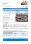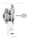
1
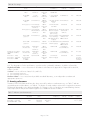
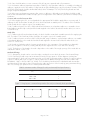
APPROVAL INSPECTION TESTING CERTIFICATION Kingspan Insulation Limited Pembridge Leominster Herefordshire HR6 9LA Tel: 01544 388 601 Fax: 01544 388 888 TECHNICAL APPROVALS FOR CONSTRUCTION Agrément Certificate 06/4372 e-mail: [email protected] website: www.insulation.kingspan.com Product Sheet 1 KINGSPAN INSULATION THERMAROOF TR27 LPC/FM AND THERMATAPER TT47 LPC/FM ROOFING BOARDS PRODUCT SCOPE AND SUMMARY OF CERTIFICATE This Certificate relates to Thermaroof TR27 LPC/FM and Thermataper TT47 LPC/FM Roofing Boards, rigid thermoset polyisocyanurate glass tissue faced insulation for use as a thermal insulation layer on limited access pitched or flat concrete, metal or timber roof decks. Thermataper TT47 LPC/FM is also for use on zero pitch roofs to create or improve falls. The products are for use in conjunction with a vapour control layer and adhesively bonded or mechanically fixed roof waterproofing membrane in domestic and non-domestic buildings. AGRÉMENT CERTIFICATION INCLUDES: • factors relating to compliance with Building Regulations where applicable • factors relating to additional non-regulatory information where applicable • independently verified technical specification • assessment criteria and technical investigations • design considerations • installation guidance • regular surveillance of production • formal three-yearly review. KEY FACTORS ASSESSED Thermal performance — the products’ have declared thermal conductivities (90/90 value) ranging from 0.024 W·m–1·K–1 to 0.026 W·m·–1·K–1 depending on thickness (see section 5). Condensation risk — the products can contribute to limiting the risk of surface condensation (see section 6). Strength and stability — when installed on suitable substrates using appropriate adhesive and/or mechanical fixing methods, the products can adequately transfer maintenance traffic loads and wind loads to the roof deck (see section 7). Behaviour in relation to fire — the fire rating of any roof containing the products will depend on the type of completed roof construction (see section 8). Durability — the products, when used as thermal insulation in the roof systems described in this Certificate, will have a life at least as long as that of the roof waterproof covering (see section 11). The BBA has awarded this Agrément Certificate to the company named above for the products described herein. These products have been assessed by the BBA as being fit for their intended use provided they are installed, used and maintained as set out in this Certificate. On behalf of the British Board of Agrément Date of First issue: 11 August 2011 Sean Moriarty Greg Cooper Originally certificated on 29 September 2006 Head of Approvals — Physics Chief Executive The BBA is a UKAS accredited certification body — Number 113. The schedule of the current scope of accreditation for product certification is available in pdf format via the UKAS link on the BBA website at www.bbacerts.co.uk Readers are advised to check the validity and latest issue number of this Agrément Certificate by either referring to the BBA website or contacting the BBA direct. British Board of Agrément Bucknalls Lane Garston, Watford Herts WD25 9BA ©2011 Page 1 of 12 tel: 01923 665300 fax: 01923 665301 e-mail: [email protected] website: www.bbacerts.co.uk Regulations In the opinion of the BBA, Thermaroof TR27 LPC/FM and Thermataper TT47 LPC/FM Roofing Boards, if used in accordance with the provisions of this Certificate, will meet or contribute to meeting the relevant requirements of the following Building Regulations: The Building Regulations 2010 (England and Wales) Requirement: A1 Loading Comment: Requirement: B4(2) External fire spread Comment: Requirement: C2(c) Resistance to moisture The products are acceptable. See section 7.1 of this Certificate. Roofs incorporating the products can meet this Requirement. See section 8.2 of this Certificate. Comment: The products will contribute to a roof meeting this Requirement. See sections 6.1, 6.3 and 6.6 of this Certificate. Requirement: L1(a)(i) Conservation of fuel and power Comment: Requirement: Regulation 7 Materials and workmanship Comment: The products are an acceptable material. See section 11 and the Installation part of this Certificate. The products can meet or contribute to meeting this Requirement. See sections 5.2 and 5.3 of this Certificate. The Building (Scotland) Regulations 2004 (as amended) Regulation: 8(1) Regulation: Standard: 9 1.1 2.8 3.15 6.1(b) 6.2 7(a)(b) Statement of sustainability The products can contribute to meeting the relevant Requirements of Regulation 9, Standards 1 to 6 and therefore will contribute to a construction meeting a bronze level of sustainability as defined in this Standard. In addition the products can contribute to a construction meeting a higher level of sustainability as defined in this Standard, with reference to clauses 7.1.4(1)(2) Aspects 1(1)(2) and 2(1), 7.1.6(1)(2) Aspects 1(1)(2) and 2(1) and 7.1.7(1)(2) Aspect 1(1)(2). See section 5.2 of this Certificate. Comment: Regulation: Carbon dioxide emissions Building insulation envelope The products can contribute to satisfying the requirements of these Standards, with reference to clauses, or parts of, 6.1.2(2), 6.1.6(1), 6.2.1(1)(2), 6.2.3(1), 6.2.4(2), 6.2.5(2), 6.2.6(1), 6.2.7(1), 6.2.8(1)(2), 6.2.9(1)(2), 6.2.10(1)(2), 6.2.11(1)(2), 6.2.12(2) and 6.2.13(1)(2). See sections 5.2 and 5.3 of this Certificate. Comment: Standard: Condensation The products will contribute to a roof meeting this Standard, with reference to clauses 3.15.1(1)(2), 3.15.3(1)(2), 3.15.4(1)(2), 3.15.5(1)(2) and 3.15.6(1)(2). See sections 6.1, 6.4 and 6.6 of this Certificate. Comment: Standard: Standard: Spread from neighbouring buildings Roofs incorporating these products can meet this Standard, with reference to clauses 2.8.1(1)(2). See section 8.2 of this Certificate. Comment: Standard: Building standards — construction Structure The products are acceptable, with reference to clauses 1.1.1(1)(2), 1.1.2(1)(2) and 1.1.3(1)(2). See sections 7.1 of this Certificate. Comment: Standard: Fitness and durability of materials and workmanship The products can contribute to a construction satisfying this Regulation. See section 11 and the Installation part of this Certificate. Comment: 12 Building standards — conversions All comments given for these products under Regulation 9, also apply to this Regulation, with reference to clause 0.12.1(1)(2) and Schedule 6(1)(2). Comment: (1) Technical Handbook (Domestic). (2) Technical Handbook (Non-Domestic). The Building Regulations (Northern Ireland) 2000 (as amended) Regulation: B2 Fitness of materials and workmanship Comment: Regulation: C5 Condensation Comment: Regulation: D1 Stability Comment: Regulation: E5(b) External fire spread Comment: Regulation: Regulation: F2(a)(i) F3(2) Conservation measures Target carbon dioxide Emissions Rate Comment: The products are acceptable. See section 11 and the Installation section of this Certificate. The products contribute to a roof meeting this Regulation. See sections 6.1 and 6.6 of this Certificate. The products are acceptable. See section 7.1 of this Certificate. Roofs incorporating the products can meet this Regulation. See section 8.2 of this Certificate. Roofs incorporating the products can satisfy or contribute to satisfying this Regulation. See sections 5.2 and 5.3 of this Certificate. Page 2 of 12 Construction (Design and Management) Regulations 2007 Construction (Design and Management) Regulations (Northern Ireland) 2007 Information in this Certificate may assist the client, CDM co-ordinator, designer and contractors to address their obligations under these Regulations. 2 Delivery and site handling (2.5) of this Certificate. See section Non-regulatory Information NHBC Standards 2011 NHBC accepts the use of Thermaroof TR27 LPC/FM and Thermataper TT47 LPC/FM Roofing Boards, when installed and used in accordance with this Certificate, in relation to NHBC Standards, Chapter 7.1 Flat roofs and balconies and Chapter 7.2 Pitched roofs. Technical Specification 1 Description 1.1 Thermaroof TR27 LPC/FM and Thermataper TT47 LPC/FM Roofing Boards are rigid thermoset polyisocyanurate insulation boards with glass-tissue facings on both sides. They are manufactured using CFC/HCFC free materials, with zero ozone depletion potential (0 ODP) and a global warming potential (GWP) of less than 5. 1.2 Boards(1) have the nominal characteristics as shown in Table 1. Table 1 Nominal characteristics Property Length (mm) Width (mm) Thickness (mm) Compressive strength at 10% compression (kPa) Density (kg·m–3) Thermaroof TR27 Thermataper TT47 2400 and 600 1200 25 to 150 in 5 mm increments 150 32 1200 1200 25 to 145 in 5 mm increments 150 32 (1) Other board sizes may be available on request. 1.3 Thermataper TT47 LPC/FM Roofing Boards are available in falls of 1:80, 1:60, 1:40 and 1:30. 1.4 Quality control checks are carried out on raw materials, during the manufacturing process and on finished boards. 1.5 The boards are installed as part of a system in conjunction with the following items: • waterproofing membrane • vapour control layer (VCL) • adhesive or fixings — incorporating countersunk washer. 2 Delivery and site handling 2.1 Boards are delivered to site in packs shrink-wrapped in polythene. Each pack carries a label bearing the company’s name, product code and batch number and the BBA logo, incorporating the number of this Certificate. 2.2 Boards must be stored flat, off the ground on a clean, level surface under cover to protect them from precipitation, moisture, high winds and mechanical damage. 2.3 Boards must be protected from prolonged exposure to sunlight by storing either under cover or by covering with opaque polythene sheets or waterproof tarpaulin. Where possible, the boards should be stored inside a building. 2.4 Wet boards should not be used. 2.5 Boards must not be exposed to naked flame or other ignition sources. Assessment and Technical Investigations The following is a summary of the assessment and technical investigations carried out on Thermaroof TR27 LPC/FM and Thermataper TT47 LPC/FM Roofing Boards. Design Considerations 3 General 3.1 Thermaroof TR27 LPC/FM and Thermataper TT47 LPC/FM Roofing Boards are suitable for use as a thermal insulation layer on concrete, metal or timber pitched or flat roofs, with access limited to maintenance only. Page 3 of 12 3.2 Decks should be designed in accordance with the relevant clauses of BS 6229 : 2003, BS 8217 : 2005, BS 8218 : 1998 and where appropriate, the NHBC Standards 2011, Chapter 7.1. 3.3 Roofs should incorporate an effective VCL below the boards. 3.4 Boards are for use with one of the following waterproofing specifications: • partially bonded built-up bitumen felt, laid in accordance with BS 8217 : 2005 • mastic asphalt laid in accordance with BS 8218 : 1998 • liquid applied systems subject of a current Agrément Certificate laid in accordance with, and within, the limitations imposed by that Certificate • PVC, CSM CPE, FPO (including TPO), VET, PIB or EPDM single-ply waterproof membranes subject of a current Agrément Certificate and laid in accordance with that Certificate. 3.5 Limited access roofs are defined for the purpose of this Certificate as those roofs subject only to pedestrian traffic for maintenance of the roof covering and cleaning of gutters, etc (see also section 7.13). 3.6 Flat roofs are defined for the purpose of this Certificate as those roofs having a minimum finished fall of 1:80 and a maximum 1:6 as defined in BS 6229 : 2003. 3.7 For design purposes on flat roofs, twice the minimum finished fall should be assumed, unless a detailed analysis of the roof is available, including overall and local deflections, direction of falls etc. 3.8 Tapered boards may be used where appropriate to achieve the minimum finished falls required. If using the tapered insulation board a fall of 1:60 will be acceptable to achieve at least 1:80 post construction falls. 3.9 Pitched roofs are defined as those having falls in excess of 1:6. 4 Practicability of installation The products are designed to be installed by a competent general builder, or a contractor, experienced with this type of product. 5 Thermal performance 5.1 Calculations of thermal transmittance (U value), should be carried out in accordance with BS EN ISO 6946 : 2007 and BRE Report (BR 443 : 2006) Conventions for U-value calculations, using the declared thermal conductivity (90/90 value) of the products as shown in Table 2. Table 2 Thermal conductivity (90/90 values) Insulation thickness (mm) Thermal conductivity (W·m–1·K–1) < 80 0.026 ≥ 80 < 120 0.025 ≥ 120 0.024 5.2 The U value of a completed roof will depend on the thickness of insulation used, the number and type of fixings and the insulating value of other roof components/layers. Example U values of roofs incorporating the products are shown in Tables 3 and 4. Table 3 Example U values — Mechanically fixed U-value requirement (W·m–2·K–1)(1) Deck construction/insulation thickness (mm) Concrete(2)(3) Timber(2)(4) Metal(2)(5) 0.13 215 215 225 0.16 175 175 185 0.18 155 155 165 0.20 140 135 145 0.25 110 110 120 (1) Thermaroof TR27 LPC/FM Roofing Boards. (2) Includes 5.55 steel fixings per m2 and 3.55 steel waterproofing fixings per m2, with a 4.8 mm cross sectional head diameter and full insulation penetration depth. (3) Concrete decking 2.0 W·m–1·K–1, 38 mm timber battens (15%), VCL, 1.5 mm single ply waterproofing membrane, 12.5 mm plasterboard. (4) 18 mm plywood decking, 150 mm timber joists (12.5%) with 150 mm airspace (87.5%), VCL, 1.5 mm single ply waterproofing membrane, 12.5 mm plasterboard. (5) Metal deck – (not included in calculation), VCL, 1.5 mm single ply waterproofing membrane. Page 4 of 12 Table 4 Example U values — Adhesively fixed U-value requirement (W·m–2·K–1)(1) 0.13 0.16 0.18 0.20 0.25 Deck construction/insulation thickness (mm) Concrete(2)(3) Timber(2)(4) Metal(2)(5) 170 135 120 115 90 170 135 120 110 90 175 145 130 120 95 (1) Thermaroof TR27 LPC/FM Roofing Boards. (2) Adhesively fixed with no metal fixings. (3) Concrete decking 2.0 W·m–1·K–1, 38 mm timber battens (15%), VCL, 1.5 mm single ply waterproofing membrane, 12.5 mm plasterboard. (4) 18 mm plywood decking, 150 mm timber joists (12.5%) with 150 mm airspace (87.5%), VCL, 1.5 mm single ply waterproofing membrane, 12.5 mm plasterboard. (5) Metal deck – (not included in calculation), VCL, 1.5 mm single ply waterproofing membrane. 5.3 The products can contribute to maintaining continuity of thermal insulation at junctions between elements and openings. For Accredited Construction Details the corresponding psi values in BRE Information Paper IP1/06 Assessing the effects of thermal bridging at junctions and around openings, Table 3 may be used in carbon emission calculations in Scotland and Northern Ireland. Detailed guidance for other junctions and on limiting heat loss by air infiltration can be found in: England and Wales — Approved Documents to Part L and for new thermal elements to existing buildings, Accredited Construction Details (version 1.0). See also SAP 2009 Appendix K and the iSBEM User Manual for new-build Scotland — Accredited Construction Details (Scotland) Northern Ireland — Accredited Construction Details (version 1.0). 6 Condensation risk Interstitial condensation 6.1 Roofs incorporating a VCL with a vapour resistance of at least 250 MN·s·g–1 will adequately limit the risk of interstitial condensation when they are designed and constructed in accordance with BS 5250 : 2002, Section 8.4 and Appendix D and BRE Report (BR 262 : 2002) Thermal insulation: avoiding risks in England and Wales. 6.2 For the purposes of assessing the risk of interstitial condensation, the boards vapour resistivity may be taken as approximately 306 MN·s·g–1·m–1. Surface condensation 6.3 Roofs will adequately limit the risk of surface condensation when the thermal transmittance (U value) does not exceed 0.35 W·m–2·K–1 at any point and the junctions with other elements are designed in accordance with section 5.3. 6.4 Roofs will adequately limit the risk of surface condensation when the thermal transmittance (U value) does not exceed 1.2 W·m–2·K–1 at any point. Guidance may be obtained from BS 5250 : 2002, Section 8 and BRE Report (BR 262 : 2002). 6.5 Alternatively, a detailed assessment in accordance with BS 5250 : 2002, Annex D, and BS EN ISO 13788 : 2002, Section 5 can be carried out to show that surface condensation and mould growth are not predicted. 6.6 Where an effective VCL is difficult to ensure, eg due to a large number of penetrations through this layer, the risk of condensation should be assessed in accordance with BS 6229 : 2003, Annex A. 7 Strength and stability 7.1 When installed on suitable roof decks, boards can adequately transfer maintenance traffic loads and negative and positive (suction and pressure) wind loads to the roof deck. 7.2 The roof construction or immediate substrate to which the boards are fixed must be structurally sound and have sufficient strength and stability to resist all dead, imposed and wind loads. It must also have adequate resistance to the pull-out forces created by the wind forces acting on the specified fixings used. 7.3 The suitability of the roof construction, and in particular the immediate substrate, to accept the adhesive bond and mechanical fixing must be checked before installation. Mechanical fixings must be checked before installation by carrying out in-situ pull-out or pull-through testing to determine the minimum safe working load the fixings can resist. The advice of the Certificate holder should also be sought in respect of suitable mechanical fixings. 7.4 The type and number of fixings will depend on the roof construction and location; the Certificate holder’s advice can be sought in this respect. The Certificate holder recommends a minimum number of fixings per board size, see section 13.12. Page 5 of 12 7.5 All design analysis must be in accordance with British or European Standards relevant to the construction. The requirement for fixings to suit the wind uplift requirements for the particular site should be assessed in accordance with BS 6399-2 : 1997 or BS EN 1991-1-4 : 2005. All calculations should be approved by a suitably competent person eg a Chartered Engineer or equivalent. 7.6 Each fixing should incorporate a head or washer which is a minimum of 50 mm diameter if round or 50 mm by 50 mm if square. Fixings installed along the edges or at corners of boards should be greater than 50 mm but less than 150 mm from the board edge. 7.7 For adhesive application of the insulation boards, the substrate must be free of dust, dry and installation should be in accordance with the instructions of the adhesive manufacturer. The surface of the substrate must have sufficient cohesive strength to resist the calculated wind load acting upon the structure. 7.8 When adhering is the chosen method for the insulation or waterproofing, adhesion between the insulation board and VCL and between the board and overlay must be adequate to resist the effects of wind suction and thermal cycling likely to be experienced under normal conditions. Metal deck profiles should give a bonding area of at least 33% of the total projected surface area. In areas where high wind speeds can be expected, additional mechanical fixings should be considered and the advice of a suitably qualified Chartered Engineer should be sought as to the method of fixing as defined in the relevant clauses of BS 6399-2 : 1997 and BS EN 1991-1-4 : 2005. 7.9 Roof waterproof systems (see section 3.4 for suitable types) must be applied in accordance with the relevant British Standards, Agrément Certificates or manufacturer’s guidance. 7.10 For design purposes, the boards may be assumed to have an allowable compressive strength of 150 kPa at 10% compression. 7.11 The boards have not been assessed for use with permanent distributed or concentrated loads, such as air conditioning units, mechanical plants, water tanks, etc. Such loads should be supported directly on the roof construction. The boards are not suitable when permanent roof access is required. 7.12 When profiled decking is used, boards will need to span across the ribs. Maximum permissible spans between ribs for board thickness are shown in Table 5. Table 5 Maximum clear span Maximum clear span (mm) < 75 > 75 > 100 > 125 > 150 > 175 > 200 > 225 ≤ ≤ ≤ ≤ ≤ ≤ ≤ Minimum roofboard thickness (mm) 25 30 35 40 45 50 55 60 100 125 150 175 200 225 250 7.13 When maintenance is required to the roof waterproofing, protective boarding should be laid over the roof surface to avoid concentrations of load. 8 Behaviour in relation to fire 8.1 The fire rating of any roof containing the boards will depend on the type of deck and the nature of the roof waterproof covering. 8.2 The constructions shown in Table 6 achieve a roof covering designation AA, AB, AC or BROOF(t4) (Low vulnerability in Scotland) rating and are acceptable for use less than 6 m from a relevant boundary. For other roof constructions, designers should refer to the relevant guidance in the documents supporting the national Building Regulations. Page 6 of 12 Table 6 Fire ratings Standard Substrate deck(1) VCL(1) Insulation Waterproofing membrane(1) Fixing method(1) 18 mm OSB timber 1.5 mm bituminous 100 mm Thermaroof TR27 1.23 mm Sarnafil G410-12EL 2170 Adhesive 0° EXT.F.AC 18 mm OSB timber 1.4 mm bituminous 100 mm Thermaroof TR27 1.2 mm Sarnafil G410-12EL 2170 Adhesive 45° EXT.S.AB 18 mm OSB timber 3 mm bituminous 100 mm Thermaroof TR27 5 mm thick Sarnafil TG76-12 Felt 2142S Adhesive 0° EXT.F.AC 12 mm plywood 2 mm Paravapo SBS metal lined bituminous 90 mm Thermaroof TR27 5 mm thick Parafor Solo GFM Mechanical 0° EXT.F.AB 12 mm plywood 3 mm Paravapo SBS metal lined bituminous 90 mm Thermaroof TR27 Graviflex Extensive Bonded by torching Green Roof System and Insta stik with live Sedum Adhesive plant covering 0° EXT.F.AA 18 mm WBP plywood 2 mm bituminous 120 mm Thermaroof TR27 2.2 mm (including Caswell ICB PU-M fleece backing) Adhesive and ICB Alwitra Evalon V DOW Insta stik single-ply 0° EXT.F.AB 18 mm WBP plywood 2 mm bituminous 120 mm Thermaroof 2.4 mm ICB Alwitra Caswell ICB PU-M XTEVA single-ply Adhesive and DOW Insta stik 0° EXT.F.AB 6 mm calcium silicate board Liquid Plastics 1.5 mm bituminous 40 mm Thermaroof TR27 Gamma 20 Liquid Plastics Decostik Adhesive 0° EXT.F.AB Classified in accordance with BS EN 13501-5 : 2005 6 mm calcium silicate board Liquid Plastics 1.5 mm bituminous 40 mm Thermaroof TR27 Gamma 20 Liquid Plastics Decostik Adhesive 0° BROOF(t4) EN 1363-1 : 1999, EN 1363-2 : 1999 and EN 1365-2 : 2000 Trapezoidal steel sheet 85A 0.75 mm S 320 G 0.2 mm foil PE 100 mm Thermaroof TR27 1.2 mm Protan PVC foil single-ply Mechanical 0° Retained specimen integrity for 31 minutes BS 476-3 : 2004 Roof Designation inclination (1) These items are outside the scope of the Certificate. Specific constructions used should be tested. 8.3 The designation of other specifications, eg when used on combustible substrates, should be confirmed by: England and Wales — test or assessment in accordance with Clause 6 of appendix A of Approved Document B, volumes 1 and 2. Scotland — test to conform to clauses 2.C(1) and 2.F(2). (1) Technical Handbook (Domestic). (2) Technical Handbook (Non-Domestic). Northern Ireland — test or assessment by a UKAS accredited laboratory, or an independent consultant with appropriate experience. 9 Acoustic performance Thermaroof TR27 LPC/FM boards have also been assessed for airborne sound transmission, see Table 7 and rain generated impact sound reduction, see Table 8. The degree of sound insulation achieved for completed constructions will depend substantially on the design and quality of construction of the roof and their associated flanking elements. Further improvements may be achieved through the use of additional acoustic insulation. Table 7 Airborne sound transmission Test method BS EN ISO 140-3 : 1995, BS 2750-3 : 1995 and BS EN ISO 140-6 : 1998 Method calculated Substrate deck(1) Insulation Waterproofing membrane(1) Fixing method(1) BS EN ISO 717-1 : 1997 0.7 mm thick galvanized steel deck 80 mm Thermaroof TR27 single-ply Mechanical (1) These items are outside the scope of the Certificate. Specific constructions used should be tested. Page 7 of 12 Roof Airborne sound inclination reduction 0° Rw (C;Ctr) = 27 (–1;–3) dB Table 8 Rain Generated Impact Sound Reduction Test Method Substrate deck(1)(2) VCL(1)(2) Insulation(1) Waterproofing Membrane(1)(2) 0.7 mm thick profiled metal deck (MF) 1.5 mm bituminous felt (A) 110 mm Thermaroof TR27 (A) 1.2 mm single ply membrane with a fleece backing (A) 0º LIA = 56.1 dB 0.7 mm thick profiled metal deck (MF) 0.2 mm polythene (MF) 110 mm Thermaroof TR27 (MF) 1.2 mm single ply membrane with a fleece backing (A) 0º LIA = 57.0 dB Draft ISO 140-18 Roof Inclination Rain generated impact sound reduction (1) (MF) = Mechanically fixed, (A) = Adhesively fixed (2) These items are outside the scope of the Certificate. Specific constructions used should be tested. 10 Maintenance No maintenance of the insulation layer will be required provided the roof waterproof covering remains intact. 11 Durability Boards are rot-resistant and durable. They will have a life at least as long as that of the roof waterproof covering. Installation 12 General 12.1 Thermaroof TR27 LPC/FM and Thermataper TT47 LPC/FM Roofing Boards must be installed in accordance with the Certificate holder’s instructions and BS 6229 : 2003, BS 8217 : 2005, or the relevant Agrément Certificate, depending on the waterproofing to be applied. 12.2 Care should be taken to ensure the deck is graded to the correct falls, is dry, clean and free from any projections or gaps. 12.3 For tapered boards to be effective in providing a uniform fall, it is essential that the structural deck is true and even. Any hollows, depressions, backfalls, found in the roof deck, must be rectified prior to laying the insulation. 12.4 The suitability of the substrate deck to accept adhesive and retain mechanical fixings must be checked prior to work commencing. 12.5 The deck to which the VCL is to be applied must be level, clean, dry and sound, and free from dust, grease and other defects which may impair restraint of the insulation boards (ie adhering and/or mechanically fixing). For adhered systems, all deck joints must be taped and, where necessary, the deck coated with bitumen primer to BS 3416 : 1991. 12.6 Where the specified VCL is other than a bituminised felt or bitumen coated foil, any fixings that penetrate the VCL should be of the self-sealing type. Advice should be sought from the Certificate holder. 12.7 On multi-storey buildings or in areas subject to high wind loads, additional mechanical fixings may be required and the advice of the Certificate holder should be sought on any limitations of use. 12.8 The mechanical fixing frequency and pattern should be predetermined in accordance with the Certificate holder’s instructions and the relevant clauses of BS 6399-2 : 1997 or BS EN 1991-1-4 : 2005. Each fixing should incorporate a minimum 50 mm by 50 mm square or a 50 mm diameter circular plate countersunk washer, which must not restrain more than one board. 12.9 To prevent moisture being trapped on, or in the insulation it is essential to: • protect the boards during laying, before the application of the roof waterproofing, or to lay the roof covering at the same time as laying the boards. However boards accidentally wetted, must be replaced before application of the waterproof layer • boards should be installed only when the ambient temperature is above 5ºC to prevent condensation. 12.10 Boards can be cut with a sharp knife or fine-toothed saw to fit around projections through the roof. 12.11 Boards are for use with the waterproofing membranes specified in section 3.4, that are laid in accordance with the relevant British Standard or subject of a current Agrément Certificate and laid in accordance with that Certificate. 12.12 Once installed, access to the roof should be restricted in accordance with section 3.5. 13 Procedure Timber decks (eg tongue-and-groove boards, plywood) 13.1 If using a bituminised felt VCL, the felt is nailed to the deck and the nail heads blanked out with hot bitumen. Laps are sealed using the appropriate grade of bitumen, a polyurethane adhesive or a suitable solvent based adhesive in accordance with BS 8217 : 2005. Page 8 of 12 13.2 Care should be taken to ensure continuity of the VCL at joints, upstands and roof penetrations. 13.3 Hot bitumen adhesive (maximum temperature of 240°C) or a polyurethane adhesive or a suitable solvent-based adhesive is applied over the VCL and the roofing boards are fully embedded into it and close butted. Thermaroof TR27 LPC/FM Roofing Boards should be laid break-bonded, whilst Thermataper TT47 LPC/FM Roofing Boards are laid using a chequer board pattern. 13.4 When using non-bituminous waterproofing systems or adhesives, all board joints and edges should be sealed with 50 mm wide aluminium foil adhesive tape, prior to the application of the adhesive system and roof waterproofing membrane. Concrete and screeded concrete decks 13.5 Before applying the VCL, a screed graded to the appropriate fall should be applied where necessary and, if adhering the VCL and insulation boards, the whole deck treated with a suitable primer. The advice of the Certificate holder should also be sought in respect of a suitable primer. 13.6 For adhered systems, the VCL is fully bonded with hot bitumen, a polyurethane adhesive or a suitable solvent based adhesive and the laps sealed, and the boards applied in the manner described for timber decks (see sections 13.3 and 13.4). Metal decks 13.7 If adhering the VCL and insulation boards, the deck should be treated with a suitable primer before applying the VCL. The advice of the Certificate holder should also be sought in respect of a suitable primer. 13.8 For adhered systems a reinforced VCL is fully bonded, using hot bitumen, a polyurethane adhesive or a suitable solvent-based adhesive, to the metal deck and the boards applied in the manner described for timber decks (see section 13.3 and 13.4). 13.9 Boards are laid either with the long axis at right angles to the corrugations of the metal deck or diagonally across the corrugations of the deck, ensuring that all joints are supported on the crown flats of the decking. 13.10 The thickness of the board to be used is dependent on the width of the trough openings of the metal deck as indicated in Table 8, section 7.12. Mechanical fixings 13.11 Alternatively, boards can be secured to timber, metal and concrete decks by means of mechanical fixings. 13.12 Each fixing should incorporate a minimum 50 mm by 50 mm square or 50 mm diameter circular plate countersunk washer, which must not restrain more than one board. The minimum number of fixings for each board size is given in Table 9 and shown in Figure 1, with the requirement of additional fixings assessed in accordance with BS 6399-2 : 1997 or BS EN 1991-1-4 : 2005: These should be placed within the individual board area and be sited more than 50 mm and less than 150 mm from the edges and corners of the board, eg giving a minimum fixing rate of 5.55 fixings per square metre for 1200 by 600 mm boards. Table 9 Minimum number of fixings (for solely mechanically fixed specification) Board dimensions (mm) Minimum number of fixings 2400 x 1200 6 1200 x 1200 4 600 x 1200 4 Figure 1 Fixing layouts – minimum fixing numbers (for solely mechanically fixed specification) Page 9 of 12 13.13 On tall buildings or in areas subject to high-wind loads, additional mechanical fixings may be required(1). The suitability of the substrate to accept and retain mechanical fixings must be checked prior to the work commencing. (1) The requirement for additional fixings must be assessed in accordance with BS 6399-2 : 1997 or BS EN 1991-1-4 : 2005. Pitched roofs 13.14 Boards should be either fully bonded or mechanically fixed to the supporting deck. Alternatively, a combination of the two methods can be used. For solely mechanically fixed boards, the fixings should be installed as specified in section 13.12, with the minimum number of fixings for each board given in Table 9. 13.15 A suitable VCL with lapped and sealed joints should be applied prior to the installation of the boards, as outlined in sections 13.1 or 13.5 to 13.8. 13.16 Boards are installed on the supporting deck in the manner described for timber decks (see sections 13.3 and 13.4). 13.17 When installing above a profile metal deck, boards can be laid either with the long axis at right angles to the corrugations of the deck, or diagonally across the corrugations of the deck, ensuring that all board joints are supported on the crown flats of the decking. 13.18 Each fixing should be installed in the manner described in section 13.12. 13.19 Waterproofing systems should then be applied above the insulation as described in section 13.20. Weatherproofing (all systems) 13.20 Waterproofing systems should be applied above the insulation boards and as noted in section 3.4. Technical Investigations 14 Tests Tests were carried out by the BBA and the results assessed to determine: • resistance to loading (free span) • resistance to peel. 15 Investigations 15.1 An assessment was made of the results of test data in accordance with MOAT No 50 : 1992 to determine: • density • compressive strength at 10% compression • dimensional stability with temperature • dimensional accuracy • thermal conductivity (fresh and aged) • water vapour resistance/resistivity • fire rating • adhesive bonding • mechanical fixings • condensation risk. 15.2 The manufacturing processes were examined, including quality control. Page 10 of 12 Bibliography BS 476-3 : 2004 Fire tests on building materials and structures — Classification and method of test for external fire exposure to roofs BS 2750-3 : 1995 Acoustics — Measurement of sound insulation in buildings and of building elements — Laboratory measurements of airborne sound insulation of building elements BS 3416 : 1991 Specification for bitumen based coatings for cold application, suitable for use in contact with potable water BS 5250 : 2002 Code of practice for control of condensation in buildings BS 6229 : 2003 Flat roofs with continuously supported coverings — Code of practice BS 6399-2 : 1997 Loading for buildings — Code of practice for wind loads BS 8217 : 2005 Reinforced bitumen membranes for roofing — Code of practice BS 8218 : 1998 Code of practice for mastic asphalt roofing BS EN 1991-1-4 : 2005 Eurocode 1 : Actions on structures — General actions — Wind actions BS EN 13501-5 : 2005 Fire classification of construction products and building elements — Classification using data from external fire exposure to roof tests BS EN ISO 140-3 : 1995 Acoustics — Measurement of sound insulation in buildings and of building elements — Laboratory measurement of airborne sound insulation of building elements BS EN ISO 140-6 : 1998 Acoustics — Measurement of sound insulation in buildings and of building elements — Laboratory measurements of impact sound insulation of floors BS EN ISO 717-1 : 1997 Acoustics — Rating of sound insulation in buildings and of building elements — Airborne sound insulation BS EN ISO 6946 : 2007 Building components and building elements — Thermal resistance and thermal transmittance — Calculation method BS EN ISO 13788 : 2002 Hygrothermal performance of building components and building elements — Internal surface temperature to avoid critical surface humidity and interstitial condensation — Calculation methods Draft ISO 140-18 Draft International Standard — Laboratory measurement of sound generated by rainfall on building elements EN 1363-1 : 1999 Fire resistance tests — General requirements EN 1363-2 : 1999 Fire resistance tests for loadbearing elements — Floors and roofs EN 1365-2 : 2000 Fire resistance tests for loadbearing elements — Floors and roofs MOAT No 50 : 1992 Technical guidelines for the assessment of thermal insulation systems intended for supporting waterproof coverings on flat and sloping roofs Page 11 of 12 Conditions of Certification 16 Conditions 16.1 This Certificate: • relates only to the product/system that is named and described on the front page • is issued only to the company, firm, organisation or person named on the front page — no other company, firm, organisation or person may hold or claim that this Certificate has been issued to them • is valid only within the UK • has to be read, considered and used as a whole document — it may be misleading and will be incomplete to be selective • is copyright of the BBA • is subject to English Law. 16.2 Publications, documents, specifications, legislation, regulations, standards and the like referenced in this Certificate are those that were current and/or deemed relevant by the BBA at the date of issue or reissue of this Certificate. 16.3 This Certificate will remain valid for an unlimited period provided that the product/system and its manufacture and/or fabrication, including all related and relevant parts and processes thereof: • are maintained at or above the levels which have been assessed and found to be satisfactory by the BBA • continue to be checked as and when deemed appropriate by the BBA under arrangements that it will determine • are reviewed by the BBA as and when it considers appropriate. 16.4 The BBA has used due skill, care and diligence in preparing this Certificate, but no warranty is provided. 16.5 In issuing this Certificate, the BBA is not responsible and is excluded from any liability to any company, firm, organisation or person, for any matters arising directly or indirectly from: • the presence or absence of any patent, intellectual property or similar rights subsisting in the product/system or any other product/system • the right of the Certificate holder to manufacture, supply, install, maintain or market the product/system • individual installations of the product/system, including their nature, design, methods, performance, workmanship and maintenance • any works and constructions in which the product/system is installed, including their nature, design, methods, performance, workmanship and maintenance • any loss or damage, including personal injury, howsoever caused by the product/system, including its manufacture, supply, installation, use, maintenance and removal. 16.6 Any information relating to the manufacture, supply, installation, use, maintenance and removal of this product/ system which is contained or referred to in this Certificate is the minimum required to be met when the product/system is manufactured, supplied, installed, used, maintained and removed. It does not purport in any way to restate the requirements of the Health and Safety at Work etc. Act 1974, or of any other statutory, common law or other duty which may exist at the date of issue or reissue of this Certificate; nor is conformity with such information to be taken as satisfying the requirements of the 1974 Act or of any statutory, common law or other duty of care. British Board of Agrément Bucknalls Lane Garston, Watford Herts WD25 9BA ©2011 Page 12 of 12 tel: 01923 665300 fax: 01923 665301 e-mail: [email protected] website: www.bbacerts.co.uk