1
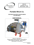
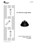
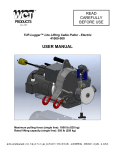
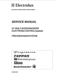
TABLE OF CONTENTS
FEATURES ........................................................................................
PRECAUTIONS .................................................................................
LOCATION OF THE CONTROLS ......................................................
INSTALLATION ..................................................................................
OPERATION DIAGRAM ....................................................................
USING THE CONTROLLER ..............................................................
Parameter Ranges .........................................................................
Factory Settings .............................................................................
The Meaning of a Flashing Display ................................................
Temperature Units .........................................................................
Room Temperature ........................................................................
RoomTemperature Display ........................................................
Probe Temperature Display .......................................................
Minimum / Maximum Temperature Recall .................................
Minimum / Maximum Temperature Reset ..................................
Temperature Set Point / Temperature Curve .............................
Stage 1 - Curtains ..........................................................................
Stage 2 - Cooling / Heating / Misting ..............................................
Alarms ............................................................................................
Manual Operation ..........................................................................
Locking the Parameters .................................................................
TROUBLESHOOTING GUIDE ...........................................................
TECHNICAL SPECIFICATIONS ........................................................
3
5
6
9
13
14
14
15
16
16
17
17
17
18
19
20
24
30
39
40
41
42
45
FOR CUSTOMER USE
Enter below the serial number
located on the side of the controller
and retain this information for future
reference.
CWS-T-11HA
Model number
Serial number
2
CWS-T-11HA.rev.03
FEATURES
The CWS-T-11HA is an electronic device used for environmental control in
livestock buildings. It allows the user to maintain a specified target temperature
by controlling the operation of ventilation and heating equipment. One stage
of either constant speed fans, heating units or mist sprinklers, as well as
curtains for natural ventilation can be connected to the controller.
The main features of the controller are as follows:
DIGITAL DISPLAY
A digital display shows temperatures and other operation
parameters.
PILOT LIGHTS
Pilot lights indicating the status of outputs allow you to
monitor the operation of the system at a distance.
TEMPERATURE CURVE
A temperature curve comprised of six different points
provides an automatic adjustment of the target room
temperature over a given period of time.
FOUR INDEPENDENT TEMPERATURE PROBE INPUTS
Up to four temperature probes can be connected to the
controller in order to obtain a more accurate reading of
the average room temperature and a faster reaction time.
HIGH/LOW TEMPERATURE AND POWER FAILURE ALARMS
The controller generates an output signal that will activate
any alarm system in case of a rise or fall in temperature
beyond a specified limit, a power failure or a fault in the
supply circuit.
CWS-T-11HA.rev.03
3
ROOM TEMPERATURE COMPENSATION ON NATURAL
VENTILATION OUTPUT (OPTIONAL)
The controller compensates the curtain timer settings
proportionally to the room temperature. The lower the room
temperature, the faster the curtains close. The higher the
room temperature, the faster the curtains open.
OVERLOAD AND OVERVOLTAGE PROTECTION
Fuses are located at the input and outputs of the controller
to protect its circuitry in the case of an overload or
overvoltage.
COMPUTER CONTROL
The controller can be connected to a computer, thus making
possible the centralization of information management and
a more diversified control strategy.
ADAPTS TO ALL TYPES OF AIR INLET POWER UNITS
4
CWS-T-11HA.rev.03
PRECAUTIONS
We strongly recommend installing a back-up thermostat on
stage 2 (refer to the wiring diagram enclosed with this
user's manual to connect the thermostat) as well as an
independent failure alarm system and a curtain drop or
manual winch .
Fuses at the input and outputs of the controller adequately
protect its circuitry in the case of an overload or overvoltage.
However, we recommend installing an additional protection
device on the supply circuit as well as an external relay on
stage 2 to prolong the life of the controller.
To avoid exposing the controller to harmful gases or
excessive humidity, it is preferable to install it in a corridor.
The room temperature where the controller is located
MUST ALWAYS REMAIN BETWEEN 0° AND 40°C (32° AND
104°F).
DO NOT SPRAY WATER ON THE CONTROLLER
CWS-T-11HA.rev.03
5
LOCATION OF THE CONTROLS
6
CWS-T-11HA.rev.03
1
Digital display
Displays temperatures and other parameters shown around the
parameter selection knob.
2
Opening pilot light
Turns on when the curtains are opening.
3
Closing pilot light
Turns on when the curtains are closing.
4
Stage 2 pilot light
Turns on when the stage 2 fans, heating units or misting units
are on.
5
Temperature curve pilot light
Turn on when the temperature curve is activated.
6
Defective probe pilot light
Turn on when a probe is defective.
7
Alarm pilot light
Turns on when the alarm is activated.
8
Locked parameter pilot light
Turns on when the parameters are locked.
9
Parameter selection knob
Used to select a parameter.
10
Push-button
Used to access the various adjustments.
11
Adjustment knob
Used to adjust the value of a selected parameter.
CWS-T-11HA.rev.03
7
13
Internal switches
Used to set the operationg modes as described in the table below.
SWITCH
DESCRIPTION
8
#
POSITION
OPERATING MODE
Parameters
1
ON
OFF
Locked parameters
Unlocked parameters
Temperature units
2
ON
OFF
° Celsius
° Fahrenheit
Probe # 2
3
ON
OFF
Probe # 2 activated
Probe # 2 deactivated
Probe # 3
4
ON
OFF
Probe # 3 activated
Probe # 3 deactivated
Probe # 4
5
ON
OFF
Probe # 4 activated
Probe # 4 deactivated
Heat/cool/mist
option
6/8
Curtain
Compensation
7
CWS-T-11HA.rev.03
Stage 2 used for heating
6: ON
6: OFF | 8: OFF Stage 2 used for cooling
6: OFF | 8: ON Stage 2 used for misting
ON
OFF
Progressive mode
Normal mode
INSTALLATION
Mounting Instructions
Remove the four screws in the front cover and lift the cover. Remove the
black caps located on the three mounting holes. Mount the enclosure to the
wall using three screws. Be sure the electrical knockouts are at the bottom
of the enclosure in order to prevent water from entering the controller.
Insert the screws into the mounting holes and tighten. Fasten the black
caps onto the mounting holes.
Connections
To connect the controller, refer to the wiring diagram enclosed with this
user's manual.
Set the voltage switch to the
appropriate line voltage.
Voltage switch
Route the cables through the
electrical knockouts provided at
the bottom of the enclosure. Do
not make additional holes in the
enclosure, particularly on the side
of the enclosure when using a
computer
communication
module.
Inside of the enclosure
CWS-T-11HA.rev.03
9
If stage 2 is used for heating, it may be necessary to install a
transformer in order to supply the correct voltage to the heating
units.
CONCERNING THE ALARM CONNECTION: There are two types of
alarms in the industry. One type activates when current is cut off at its input,
whereas the other activates when current is supplied at its input. For an
alarm of the first type, use the NO terminal as shown in the wiring diagram.
For an alarm of the second type, use the NC terminal.
ALL WIRING MUST BE DONE BY AN AUTHORIZED ELECTRICIAN AND MUST COMPLY WITH APPLICABLE CODES,
LAWS AND REGULATIONS. BE SURE POWER IS OFF
BEFORE DOING ANY WIRING TO AVOID ELECTRICAL
SHOCK AND EQUIPMENT DAMAGE.
Temperature Probes
The controller is supplied with one temperature probe connected to terminal
# 1.
CAUTION : The probes operate under low voltage and are isolated from the
supply. Be sure the probe cables remain isolated from all high voltage
sources. Do not route the probe cables and other power cables through the
same electrical knockout. Do not run the probe cables next to other power
cables. When crossing over other cables, cross at 90o.
Extending the probes
Each probe can be extended up to 500 feet (150 meters). To extend a probe:
Use a shielded cable of outside diameter between 0.245 and
0.260 in (6.22 and 6.60 mm) to ensure the cable entry is liquidtight (the cable dimension should not be under 18 AWG).
10
CWS-T-11HA.rev.03
It is preferable to weld the cable joint to ensure a proper contact
between the two cables.
Do not ground the shielding.
Connecting Additional Probes
Three additional probes may be connected to the controller in order to
obtain a more accurate reading of the average room temperature and a
faster reaction time.
Connect each additional probe using terminals # 2, # 3 and # 4,
as shown on the wiring diagram enclosed with this user’s manual.
Switches are used to activate or deactivate the additional probes connected
to the controller.
Activate each additional probe by
setting the appropriate switch to ON:
Switch # 3 activates the probe connected to terminal # 2.
Switch # 4 activates the probe connected to terminal # 3.
Switch # 5 activates the probe connected to terminal # 4.
FACTORY SETTING: When the controller is shipped from the factory,
switches # 3, # 4 and # 5 are set to OFF (probes are deactivated).
CWS-T-11HA.rev.03
11
Defective Probes
If one or many probes are defective, the defective probe pilot light turns on.
The average temperature measured by the probes remaining in proper
condition is displayed when the parameter selection knob is set to
ROOM TEMPERATURE and the controller operates according to this
temperature. If all the probes are defective, the display shows the letter "P"
when the parameter selection knob is set to ROOM TEMPERATURE, the
controller stops operating the stages and activates the alarm.
To identify the defective probe:
Set the selection knob to ROOM
TEMPERATURE. The room temperature
is displayed.
Press the push-button. If the probe
connected to terminal # 1 and supplied
with the controller is not defective, "PR1"
is displayed, alternating with the temperature measured by the probe. Otherwise,
"PR1" is displayed, alternating with "P".
For each additional probe connected to
the controller:
Press the push-button once again. If the probe is not defective, "PR#"
is displayed (where # is the number of the terminal the probe is connected
to), alternating with the temperature measured by the probe. Otherwise,
"PR#" alternates with "P".
12
CWS-T-11HA.rev.03
Heat / Cool / Mist Options
Stage 2 can be used either for
cooling, heating or mist cooling.
Set switch # 6 to the required position:
6: ON for stage 2 to operate as a heating stage.
6: OFF / 8: OFF for stage 2 to operate as a cooling stage.
6: OFF / 8: ON for stage 2 to operate as a mist cooling stage.
FACTORY SETTING: When the controller is shipped from the factory,
switches # 6 and #8 are set to ON (stage 2 operates as a heating stage).
CWS-T-11HA.rev.03
13
USING THE CONTROLLER
Parameter Ranges
PARAMETER
TEMPERATURE SET POINT
STAGE 1 CURTAINS
STAGE 2 COOLING
OR
HEATING
ADJUSTMENT RANGE
-40.0° to 99.9°F (-40° to 37.7°C)
Differential
0.5° to 20.0°F (0.3° to 11.1°C)
Time opening
1 to 900 seconds
Time closing
1 to 900 seconds
Time off
0 to 900 seconds
Differential
0.5° to 20.0°F (0.3° to 11.1°C)
Heating Offset
- activated
- deactivated
-9.9° to 20.0°F (-5.5° to 11.1°C)
0.0° to 20.0°F (0.0° to 11.1°C)
Time on
0 to 900 seconds, by
increments of 15 seconds
Time off
0 to 900 seconds, by
increments of 15 seconds
High offset
0.5° to 40.0°F (0.3° to 22.2°C)
Low offset
0.5° to 40.0°F (0.3° to 22.2°C)
ALARM
14
CWS-T-11HA.rev.03
Factory Settings
The controller is programmed at the factory with the settings shown
below. Keep the settings that are convenient for you and make changes
where necessary.
NOTES: (1) The controller only memorizes the last parameter settings.
Each new setting replaces the preceding one.
(2) If the power supply is cut off, the last parameter setting
will be kept in memory until the power is restored.
PARAMETER
FACTORY SETTING
Set point
75.0°F (23.9°C)
Temperature curve
OFF
Differential
3.0°F (1.7°C)
STAGE 1 -
Time opening
20 seconds
CURTAINS
Time closing
20 seconds
Time off
60 seconds
Differential
2.0°F (1.1°C)
Offset
0.5°F (0.3°C)
Time on
15 seconds
Time off
30 seconds
High offset
12.0°F (6.7°C)
Low offset
10.0°F (5.6°C)
TEMPERATURE
SET POINT
STAGE 2 COOLING
OR
HEATING
ALARM
CWS-T-11HA.rev.03
15
The Meaning of a Flashing Display
The display flashes certain
values and does not flash
others. The flashing indicates
that the displayed value
can be adjusted. A value
that is not flashing can not
be adjusted.
Temperature Units
Temperatures can be displayed either in
degrees Celsius or in degrees Fahrenheit.
Set switch # 2 to the desired position:
ON to display temperatures in degrees Celsius.
OFF to display temperatures in degrees Fahrenheit.
FACTORY SETTING: When the controller is shipped from the factory,
switch # 2 is set to OFF (temperatures are displayed in degrees Fahrenheit).
16
CWS-T-11HA.rev.03
Room Temperature
Room Temperature Display
The room temperature is the average value of all temperatures measured
by probes that are activated and in proper operating condition.
DISPLAYING THE ROOM TEMPERATURE
Set the parameter selection knob to ROOM TEMPERATURE.
The room temperature appears on the display.
Probe Temperature Display
DISPLAYING PROBE TEMPERATURES
Set the parameter selection knob to ROOM TEMPERATURE.
The ambient temperature appears on the display.
Press the push-button. "PR1" is displayed, alternating with the
temperature measured by the probe connected to terminal # 1
(supplied with the controller).
CWS-T-11HA.rev.03
17
DISPLAYING PROBE TEMPERATURES (CONT'D)
For each additional probe connected to the controller:
Press the push-button again. "PR#" (where # is the terminal
number to which the probe is connected) is displayed, alternating
with the temperature measured by the probe.
Minimum / Maximum Temperature Recall
The minimum and maximum temperatures are the lowest and highest
values of all room temperatures measured since the last reset.
RECALLING MINIMUM AND MAXIMUM
TEMPERATURES
Set the parameter selection knob to ROOM TEMPERATURE.
The room temperature appears on the display.
Turn the adjustment knob clockwise by one notch. The minimum
temperature appears flashing on the display.
Turn the adjustment knob clockwise one notch further. The
maximum temperature appears flashing on the display.
Turn the adjustment knob clockwise a third notch. The room
temperature again appears on the display.
If the adjustment knob is turned counterclockwise rather than
clockwise, the display sequence will be reversed (room-maximumminimum-room).
18
CWS-T-11HA.rev.03
Minimum / Maximum Temperature Reset
The reset erases the current minimum and maximum temperatures. From
the moment the reset is completed, the controller begins to store in memory
the new minimum and maximum temperatures measured by the probes.
RESETTING MINIMUM AND MAXIMUM
TEMPERATURES
Set the parameter selection knob to ROOM TEMPERATURE.
The room temperature appears on the display.
Turn the adjustment knob clockwise (or counterclockwise) by
one notch and leave it in this position. The minimum (or
maximum) temperature first appears flashing on the display.
After 10 seconds, the display stops flashing and the room
temperature again appears on the display, indicating that the
reset is completed.
NOTE : To avoid resetting the minimum et maximum temperatures
while recalling them, be sure to return to the room temperature
display within the 10 second delay.
CWS-T-11HA.rev.03
19
Temperature Set Point / Temperature Curve
There are two ways to specify the target room temperature:
1 Adjust the temperature set point to the desired value and do not activate the
temperature curve. The controller will operate according to this target room
temperature as long as the temperature curve remains deactivated.
2 Program a temperature curve comprised of six points and activate the
temperature curve. For each of the six points, you must specify a day
number and a temperature set point for this day number. The controller
will automatically change the target room temperature every hour in a
linear fashion between two consecutive points. When the last point is
reached, the temperature curve becomes deactivated. The controller
continues to operate according to the last temperature set point until you
activate the temperature curve once again or specify a new temperature
set point. You can also deactivate the temperature curve before the last
point is reached.
The temperature set point and the points of the temperature curve can
be adjusted only if the temperature curve is deactivated:
If the temperature curve pilot light is off, the temperature curve is
presently deactivated and you can proceed with the adjustment.
If the temperature curve pilot light is on, the temperature curve is
presently activated. Before proceeding with the adjustment, deactivate
the curve as follows.
To deactivate the temperature curve
Set the parameter selection knob to SET POINT/ TEMP.CURVE.
The current temperature set point appears flashing on the display.
Press the push-button repeatedly until the word ON appears
flashing on the display.
Turn the adjustment knob counterclockwise one notch and leave it
in this position for at least 10 seconds. The word OFF appears
flashing on the display and after 10 seconds, the temperature
curve pilot light turns off, indicating that the temperature curve is
now deactivated. Set the parameter selection knob to ROOM
TEMPERATURE.
20
CWS-T-11HA.rev.03
ADJUSTING THE TEMPERATURE SET POINT
Be sure the temperature curve is deactivated (see above).
Set the parameter selection knob to SET POINT/ TEMP.CURVE.
The current temperature set point appears flashing on the
display.
Using the adjustment knob, adjust the set point to the desired
value.
PROGRAMMING THE TEMPERATURE CURVE
NOTES:
All six points of the curve must be specified. If you do
not need six different points, repeat your last temperature set point
for each unnecessary point of the curve.
To reduce the risk of errors:
-
The highest possible day number is 99.
You can not specify decreasing day numbers.
You can not specify an increasing temperature curve.
The temperature variation can not exceed 3°F (1.6°C) per day.
To specify the six points of the temperature curve:
Be sure the temperature curve is deactivated (see above).
Set the parameter selection knob to SET POINT/TEMP.CURVE.
The current temperature set point appears flashing on the
display.
Press the push-button. The word OFF appears on the display,
indicating that the temperature curve is deactivated.
CWS-T-11HA.rev.03
21
PROGRAMMING THE TEMPERATURE CURVE (CONT'D)
Repeat the following steps for each of the six points:
Press the push-button once again. A day number, preceded
by the letter "d", appears flashing on the display.
Using the adjustment knob, adjust the day number to the
desired value.
Press the push-button once again. The current temperature
set point for this day number appears flashing on the display.
Using the adjustment knob, adjust the temperature set point
to the desired value.
When the six points of the temperature curve have been specified,
activate the curve as follows.
To activate the temperature curve
Press the push-button once again. The word OFF appears
flashing on the display.
Turn the adjustment knob clockwise one notch and leave it in
this position for at least 10 seconds. The word ON appears
flashing on the display and after 10 seconds, the temperature
curve pilot light turns on, indicating that the temperature curve
is now activated.
Set the parameter selection knob to ROOM TEMPERATURE.
22
CWS-T-11HA.rev.03
PROGRAMMING THE TEMPERATURE CURVE (CONT'D)
NOTE: When the temperature curve is activated, the current target
room temperature and the current day number can be viewed at any
time. The current day number can also be adjusted to move forward
or backward on the temperature curve.
To display the temperature set point and to display and adjust
the current day number:
Set the parameter selection knob to SET POINT / TEMP.CURVE.
The current temperature set point appears flashing on the display.
Press the push-button. The current day number is displayed.
Use the adjustment knob to set the day number to the desired
value.
CWS-T-11HA.rev.03
23
Stage 1 - Curtains
Description of Operation
(
Refer to figure 1 on next page)
When the room temperature rises to "temperature set point + differential" (point 1), the curtains begin to open and continue to do so as long
as the room temperature remains above this point. The curtains open intermittently according to the time opening and time off settings:
During TIME OPENING, the
curtains open.
During TIME OFF, the curtains
stop opening.
When the room temperature falls to "temperature set point - differential" (point
2), the curtains begin to close and continue to do so as long as the room
temperature remains below this point. The curtains close intermittently according to the time closing and time off settings:
During TIME CLOSING, the
curtains close.
During TIME OFF, the curtains
stop closing.
24
CWS-T-11HA.rev.03
CWS-T-11HA.rev.03
25
Curtain Operating Time Compensation as a Function
of Room Temperature
1 When switch # 7 is set to OFF (normal mode):
The curtains open and close intermittently according
to the specified time opening, time closing and time off,
as described on the previous page. There is no room
temperature compensation.
2 When switch # 7 is set to ON (progressive mode):
The controller compensates the time opening, time closing and time off
according to the room temperature, as described hereafter:
When the curtains open:
Each time the room temperature rises by a certain number of degrees above "temperature set point + differential" , the controller multiplies the time opening by a given factor and reduces the time off so that
the total cycle time remains constant.
The higher the room temperature, the faster the curtains open. When
the time off is below 10 seconds, the curtains begin to open continuously.
When the curtains close:
Each time the room temperature falls by a certain number of degrees below "temperature set point - differential" , the controller multiplies the time closing by a given factor and reduces the time off so that
the total cycle time remains constant.
The lower the room temperature, the faster the curtains close. When
the time off is below 10 seconds, the curtains begin to close continuously.
26
CWS-T-11HA.rev.03
Table 1 below shows multiplication factors used when the room temperature rises above the set point plus the differential (curtains open)
or falls below the set point minus the differential (curtains close).
EXAMPLE. Suppose that you have specified the following values:
When the room temperature rises to "temperature set point + differential + 1°F (0.6°C)":
When the room temperature rises to "temperature set point + differential + 2°F (1.2°C)":
When the room temperature rises to "temperature set point + differential + 3°F (1.8°C)":
CWS-T-11HA.rev.03
27
When the room temperature rises to "temperature set point + differential + 4°F (2.2°C)", the time off is below 10 seconds. The curtains therefore begin to open continuously:
ADJUSTING THE CURTAIN PARAMETERS
ADJUSTING THE CURTAIN DIFFERENTIAL
Set the parameter selection knob to CURTAINS -DIFFERENTIAL. The current curtain differential appears flashing on
the display.
Using the adjustment knob, adjust the differential to the desired
value.
ADJUSTING THE CURTAIN TIME OPENING
Set the parameter selection knob to CURTAINS - TIME
OPENING. The current curtain time opening appears flashing
on the display.
Using the adjustment knob, adjust the time opening to the
desired value.
28
CWS-T-11HA.rev.03
ADJUSTING THE CURTAIN TIME CLOSING
Set the parameter selection knob to CURTAINS - TIME
CLOSING. The current curtain time closing appears flashing
on the display.
Using the adjustment knob, adjust the time closing to the
desired value.
ADJUSTING THE CURTAIN TIME OFF
Set the parameter selection knob to CURTAIN - TIME OFF.
The current curtain time off appears flashing on the display.
Using the adjustment knob, adjust the time off to the desired
value.
CWS-T-11HA.rev.03
29
Stage 2 - Cooling / Heating / Mist Cooling
COOLING MODE
Description of Operation
(
Refer to figure 2 on next page)
If the room temperature rises (Figure 2.a):
• When the room temperature rises to "temperature set point + offset +
differential" (point 3), the fans begin to run according to the cooling timer
settings.
• When the room temperature rises to " temperature set point + offset + differential " (point 3), the fans operate nonstop.
If the room temperature falls (Figure 2.b):
• When the room temperature is greater than "temperature set point +
offset" (point 4), the fans operate nonstop.
• When the room temperature falls to " temperature set point + offset " (point 4), the fans begin to run according to the cooling timer
settings.
30
CWS-T-11HA.rev.03
CWS-T-11HA.rev.03
31
Cooling Timer Operation:
Cooling timer:
During TIME ON, the fans are on.
During TIME OFF, the fans are off.
To run the fans intermittently: set TIME ON to the desired on time and
TIME OFF to the desired off time.
To run the fans continuously: set TIME OFF to zero and TIME ON to any
value other than zero.
To stop the fans: set TIME ON to zero and TIME OFF to any value (equal
to or other than zero).
ADJUSTING THE COOLING PARAMETERS
ADJUSTING THE COOLING DIFFERENTIAL
Set the parameter selection knob to STAGE 2 - DIFFERENTIAL. The current cooling differential appears flashing on the
display.
Using the adjustment knob, adjust the differential to the desired
value.
ADJUSTING THE COOLING OFFSET
Set the parameter selection knob to STAGE 2 - OFFSET. The
current cooling offset appears flashing on the display.
Using the adjustment knob, adjust the offset to the desired
value.
32
CWS-T-11HA.rev.03
ADJUSTING THE COOLING TIMER
Set the parameter selection knob to STAGE 2 - TIMER. The
word ON and the current cooling time on alternately appear
flashing on the display.
Using the adjustment knob, adjust the time on to the desired
value.
Press the push-button. The word OFF and the current cooling
time off alternately appear flashing on the display.
Using the adjustment knob, adjust the time off to the desired
value.
CAUTION : On and off times are in seconds.
HEATING MODE
Description of operation
(
Refer to figure 3 on next page)
If the room temperature rises (Figure 3.a):
• When the room temperature is below "temperature set point - offset"
(point 5), the heating units are on.
• When the room temperature rises to "temperature set point - offset"
(point 5), the heating units turn off.
If the room temperature falls (Figure 3.b):
• When the room temperature is greater than "temperature set point offset - differential" (point 6), the heating units are off.
• When the room temperature falls to "temperature set point - offset differential" (point 6), the heating units turn on.
NOTE: Heating units do not operate with the timer.
CWS-T-11HA.rev.03
33
34
CWS-T-11HA.rev.03
ADJUSTING THE HEATING PARAMETERS
ADJUSTING THE HEATING DIFFERENTIAL
Set the parameter selection knob to STAGE 2 DIFFERENTIAL. The current heating differential appears
flashing on the display.
Using the adjustment knob, adjust the differential to the
desired value.
ADJUSTING THE HEATING OFFSET
The heating offset is the number of degrees below the set point at
which the heating units turn off. The heating offset can provide substantial energy savings if correctly adjusted according to the outside
temperature.
When the heating offset is disabled, it can only be set to a positive
value. When enabled, it can be adjusted to a positive or negative
value. A negative value lets the heating units operate at ambient
temperatures greater than the set point.
Enabling / Disabling the Heating Offset
Set the selection knob to STAGE 2 - OFFSET. The current
offset value flashes on the display.
Press the push-button. The status of the offset is displayed, i.e.
ON/OFF. Turn the adjustment knob one knotch to the right to enable the offset (the display flashes ON), or one knotch to the left to
disable the offset (the display flashes OFF).
CWS-T-11HA.rev.03
35
ADJUSTING THE HEATING OFFSET
Set the parameter selection knob to STAGE 2 - OFFSET. The
current heating offset appears flashing on the display.
Using the adjustment knob, adjust the offset to the desired
value.
MIST COOLING MODE
DESCRIPTION OF OPERATION
(
Refer to figure 4 on next page)
If the room temperature rises (Figure 4.a):
• When the room temperature is less than "temperature set point + offset +
differential" (point 7), the misting units are turned off.
• When the room temperature rises to "temperature set point + offset +
differential" (point 7), the misting units operate according to the mist timer.
If the room temperature falls (Figure 4.b):
• When the room temperature is greater than "temperature set point +
offset" (point 8), the misting units operate according to the mist timer.
• When the room temperature falls to "temperature set point + offset"
(point 8), the misting units are turned off..
36
CWS-T-11HA.rev.03
CWS-T-11HA.rev.03
37
ADJUSTING THE MIST PARAMETERS
ADJUSTING THE MIST DIFFERENTIAL
Set the parameter selection knob to STAGE 2 - DIFFERENTIAL. The current differential appears flashing on the display.
Using the adjustment knob, adjust the differential to the desired
value.
ADJUSTING THE MIST OFFSET
Set the parameter selection knob to STAGE 2 - OFFSET. The
current offset appears flashing on the display.
Using the adjustment knob, adjust the offset to the desired
value.
ADJUSTING THE MIST TIMER
Set the parameter selection knob to STAGE 2 - TIMER. The
word ON and the current time on alternately appear flashing on
the display.
Using the adjustment knob, adjust the time on to the desired
value.
Press the push-button. The word OFF and the current time off
alternately appear flashing on the display.
Using the adjustment knob, adjust the time off to the desired
value.
CAUTION : On and off times are in minutes..
38
CWS-T-11HA.rev.03
Alarms
High Temperature Alarm
The controller activates the alarm when the room temperature rises to
“temperature set point + high offset”.
ADJUSTING THE HIGH OFFSET
Set the parameter selection knob to ALARM OFFSET - HIGH.
The current high offset appears flashing on the display.
Using the adjustment knob, adjust the high offset to the desired
value.
Low Temperature Alarm
The controller activates the alarm when the room temperature falls to
“temperature set point - low offset”.
ADJUSTING THE LOW OFFSET
Set the parameter selection knob to ALARM OFFSET - LOW.
The current low offset appears flashing on the display.
Using the adjustment knob, adjust the low offset to the desired
value.
CWS-T-11HA.rev.03
39
POWER FAILURE, SUPPLY CIRCUIT FAULT OR FAILURE OF ALL PROBES
The controller activates the alarm in the event of a power failure, a fault in
the supply circuit or a failure in all probes.
Manual Operation
Manual operation allows you to interrupt the operation of the curtains.
When the parameter selection knob is set to MANUAL OPERATION, the
curtains do not operate. When the parameter selection knob is set to any
position other than MANUAL OPERATION, the curtains operate according
to the parameter settings.
Manually Operating the Curtains
Set the selection knob to the MANUAL position. The display
flashes OFF and stops the curtains after five seconds.
Press the push-button. The display flashes OPE and the
curtains start opening after five seconds.
Press the push-button once again. The display flashes CLO
and the curtains start closing after five seconds.
Keep pressing the push-button to stop, open and close the
curtains in that order.
40
CWS-T-11HA.rev.03
Locking the Parameters
Locking the parameters prevents accidental or unauthorized modification
of the parameter settings. When the parameters are locked, only the room
set point can be modified (if the temperature curve is deactivated). All
other settings can not be modified.
LOCKING / UNLOCKING THE PARAMETERS
Set switch # 1 to ON to lock the parameters.
Set switch # 1 to OFF to unlock the parameters.
FACTORY SETTING: When the controller is shipped from the factory,
switch # 1 is set to OFF (the parameters are unlocked).
CWS-T-11HA.rev.03
41
TROUBLESHOOTING GUIDE
CAUSE
PROBLEM
SOLUTION
The circuit breaker
at the service panel
is off or tripped.
Reset the circuit breaker.
The wiring is
incorrect.
Correct the wiring.
The F6 input fuse is
open.
Replace the fuse.
The voltage selector
switch is in the
wrong position.
Set the switch to the correct
position.
The display board
interconnect cable
is not properly
plugged into the
power supply board.
Be sure the cable is firmly
plugged in.
The display
shows "P" and
the defective
probe pilot light
is on.
All the probes
connected to the
controller are
defective.
Replace the probes.
The defective
probe pilot light
is on.
A room probe is
defective.
Replace the probe. Refer to
"defective probes"
There is no
display.
42
CWS-T-11HA.rev.03
PROBLEM
The display
shows sudden
variations in the
ambient
temperature.
The fans or
heating units
are not running.
CAUSE
SOLUTION
A variation in
resistance is
induced on a
probe.
Be sure the probes are dry.
Locate them away from drafts
and sources of radiant heating.
There is electrical
noise near a probe
cable.
Isolate the probe cables from
all high voltage sources. Do
not route probe cables and
other power cables through the
same electrical knockout. Do
not run probe cables next to
other power cables. When
crossing other power cables,
cross at 90°.
The wiring is
incorrect.
Correct the wiring. Be sure two
different lines are connected to
each fan motor or heating unit:
line L1 modulated by the
controller should be combined
with another line (N for 115V or
L2 for 230V) to activate the fan
or heating unit. Also, be sure
the stage 2 COMMON is
supplied by line L1.
The stage 2 fuse is
open.
Replace the fuse.
The display board
interconnect cable
is not properly
plugged into the
power supply board.
Be sure the cable is firmly
plugged in.
CWS-T-11HA.rev.03
43
PROBLEM
CAUSE
SOLUTION
The fan motor or
heating unit is
defective.
Check if the motor or heating
unit is defective by connecting
it to an alternate power supply.
If it still is not operating,
replace the motor or heating
unit.
The controller is
defective.
Listen to see if there is a
clicking sound when the
stage 2 pilot light turns on. If
there is no clicking sound, your
controller needs repair.
The curtains do
not work.
The F1 fuse on the
stage 1 output is
blown.
Replace the fuse.
The curtains operate in manual
mode but not in
automatic
mode.
The curtain operating parameters are
set incorrectly.
Correct the parameter settings.
See "Stage 1 - Curtains".
The fans or
heating units
are not running.
(continued)
TECHNICAL SPECIFICATIONS
Supply: - 115/230 VAC (-18%,+8%), 50/60 Hz, overload and overvoltage
protection fuse F6-1A fast blow.
- 12 VDC for AC back-up supply, can activate curtains, Stage 2
and alarm if supplied with DC back-up voltage.
Curtain: OPEN-CLOSE output, 115/230 VAC, 50/60 Hz, 5A winch output,
fuse F1-5A slow blow.
Stage 2: ON-OFF output, 115/230 VAC, 50/60 Hz, 30VDC, 6A FAN, 10A
RES, heating or ventilation, fuse F3-10A slow blow.
Alarm: ON-OFF output, 115/230 VAC, 50/60 Hz, 30 VDC, 3A, fuse F5-3A
slow blow.
Probes: Low voltage (< 5V), isolated from the supply. Operating Range: 40.0 to 48.9 oC (-40.0 oF to 120.0 oF); Accuracy: 1.8°F (1°C) between 41° and
95°F (5° and 35°C).
Enclosure: ABS, moisture and dust-tight.
The temperature where the controller is installed MUST AT
ALL TIMES REMAIN BETWEEN 32 AND 104 oF (0 and 40 oC).
NOTES
46
CWS-T-11HA.rev.03