1
USER MANUAL
Part Number: NP25AEN
Version: B
BM 25A
2
GAS DETECTION
We are delighted that you have chosen an OLDHAM instrument and would like to thank you for your
choice.
We have taken all the necessary measures to ensure that your instrument provides total satisfaction.
Now it is important to read this document carefully.
EXTENT OF RESPONSIBILITY
* OLDHAM declines its responsibility towards any person for material damage, physical injury or death resulting
wholly or partly from inappropriate use, installation or storage of its equipment resulting from failure to observe
instructions and warnings and/or standards and regulations in force.
* OLDHAM neither supports nor authorises any company, physical or moral person to assume responsibility on
behalf of OLDHAM, even if it is involved in the sale of OLDHAM products.
* OLDHAM cannot be held responsible for direct or indirect damage or be required to pay direct or indirect
compensation resulting from the sale or use of any of its products IF THESE PRODUCTS HAVE NOT BEEN
DEFINED AND CHOSEN BY OLDHAM FOR SUCH USE.
CLAUSES CONCERNING PROPERTY
* Drawings, plans, specifications and information included in this document contain confidential information that is
the property of OLDHAM.
* None of this information may be reproduced, copied, divulged or translated, by physical, electronic or any other
means, nor used as the basis for the manufacture or sale of OLDHAM equipment or for any other reasons without
prior consent from OLDHAM.
WARNINGS
* This document is not contractually binding. In the interests of its customers, OLDHAM reserves to modify
the technical specifications of its equipment without notice, in order to improve product performance.
* READ THIS MANUAL CAREFULLY BEFORE FIRST USE OF THE EQUIPMENT: this manual must be
read by any person who is or will be responsible for using, maintaining or repairing this equipment.
* This equipment will only provide the announced performance levels if it is used, maintained and repaired
according to OLDHAM directives, by OLDHAM personnel or by personnel approved by OLDHAM.
GUARANTEE
* 2 years guarantee in normal conditions of use on parts and labour, return in our workshops, excluding consumables
(sensors, filters, etc.).
3
4
CONTENTS
I.
INTRODUCTION ...................................................................................................................... 9
1.
POWER ............................................................................................................................. 9
1.1.
1.2.
2.
SENSORS ....................................................................................................................... 10
2.1.
2.2.
3.
4.
5.
6.
II.
Sensor location (examples) ............................................................................................... 10
Combustible, toxic gases and oxygen sensors .................................................................. 11
DISPLAY UNIT ............................................................................................................. 11
VISUAL INDICATIONS ............................................................................................... 11
AUDIBLE ALARMS...................................................................................................... 11
SAMPLING .................................................................................................................... 12
6.1.
6.2.
6.3.
6.4.
6.5.
7.
Power supply ...................................................................................................................... 9
1.1.1. Charging the battery pack ....................................................................................... 9
1.1.2. Trickle charge ......................................................................................................... 9
Memory saving ................................................................................................................... 9
Operating instructions ....................................................................................................... 12
Electrical pumping system (not CSA certified) ................................................................ 12
Manual pumping system ................................................................................................... 12
Different probes for manual and electrical pump ............................................................. 12
Gas detector mode ............................................................................................................ 12
COMMUNICATION SOFTWARE COM 2100 ............................................................ 13
UTILIZATION ......................................................................................................................... 15
1.
2.
3.
KEYBOARD................................................................................................................... 15
READING MEASUREMENTS ..................................................................................... 15
STARTING UP ............................................................................................................... 16
3.1.
3.2.
3.3.
Starting up in standard mode ............................................................................................ 16
Starting up with choice of reference explosive gas .......................................................... 16
Start-up test and calibration due ....................................................................................... 17
4. SHUTTING DOWN ............................................................................................................. 17
5.
DISPLAY BACKLIGHTING ......................................................................................... 17
6.
SCROLLING THROUGH SET PARAMETERS .......................................................... 17
6.1
7.
ALARMS ........................................................................................................................ 18
7.1.
7.2.
7.3.
7.4.
8.
“Roundsman” function ..................................................................................................... 18
“Gas” alarms ..................................................................................................................... 18
Fault alarms ...................................................................................................................... 19
Gas alarms acknowledgement .......................................................................................... 19
7.3.1. Manual acknowledgement .................................................................................... 19
7.3.2. Automatic acknowledgement................................................................................ 19
Alarm transfer ................................................................................................................... 20
MEASUREMENTS ........................................................................................................ 20
8.1
8.2
Display of instantaneous readings .................................................................................... 20
8.1.1. Diffusion mode ..................................................................................................... 20
8.1.2 With electric pump systems (the pump is not certified by CSA) .......................... 21
8.1.3 With manual pump systems .................................................................................. 21
Memorizing histogram measurements .............................................................................. 21
8.2.1. Operating principle: memorized items .................................................................. 21
8.2.2. Memory capacity .................................................................................................. 22
8.2.3. Data storage time .................................................................................................. 22
5
III.
SPECIAL INSTRUCTIONS FOR USE IN EXPLOSIVE ATMOSPHERES OR
HAZARDOUS LOCATIONS .................................................................................................. 23
1.
2.
ATEX AREAS AND GENERAL RULES ..................................................................... 23
ATEX ZONES: INPUT/OUTPUT PARAMETERS ...................................................... 24
2.1.
2.2.
2.3.
2.4.
3.
4.
IV.
CSA HAZARDOUS LOCATIONS: INPUT/OUTPUT PARAMETERS ..................... 24
MARKING ...................................................................................................................... 28
MAINTENANCE ..................................................................................................................... 29
1.
ACCESS TO MAINTENANCE MENUS ...................................................................... 29
1.1.
1.2.
1.3.
1.4.
1.5.
V.
Channel settings ................................................................................................................ 29
1.1.1. List of pre-programmed “explo" gases and coefficients ....................................... 30
Sensor calibration menu ................................................................................................... 31
Auto-zero menu ................................................................................................................ 31
Date and time management menu ..................................................................................... 31
Exit menu .......................................................................................................................... 31
COM 2100 SOFTWARE.......................................................................................................... 33
1.
2.
INSTRUMENT CONNECTION .................................................................................... 34
MAINTENANCE ........................................................................................................... 35
2.1.
2.1.1.
2.1.2.
2.1.3.
2.2.
2.3.
2.4.
2.5.
3.
4.
VI.
Gas detector recharge connector ....................................................................................... 24
Connector for alarm outputs / fault and digital TOR inputs ............................................. 24
External power connector ................................................................................................. 24
Connector accessories / options ........................................................................................ 24
Configuration .................................................................................................................... 35
Channel settings ................................................................................................................ 35
Alarm settings ................................................................................................................... 36
Combustible gas selection ................................................................................................ 36
Calibration ........................................................................................................................ 36
Time and Date settings ..................................................................................................... 37
Monitoring reports ............................................................................................................ 37
Status Report..................................................................................................................... 39
CONFIGURATION OF ALARM RELAY AND LOGIC INPUTS FOR THE BM 25A:40
SCREENS ....................................................................................................................... 41
CHARGERS ............................................................................................................................. 43
1.
2.
3.
INTRODUCTION........................................................................................................... 43
CHARGING THE BATTERY ....................................................................................... 43
TRICKLE CHARGE ...................................................................................................... 43
3.1.
Connection ........................................................................................................................ 43
VII. DISPOSAL ............................................................................................................................... 45
VIII. ACCESSORIES........................................................................................................................ 45
IX.
SPARE PARTS ........................................................................................................................ 47
X.
TECHNICAL CHARACTERISTICS ...................................................................................... 49
1.
2.
XI.
DESCRIPTION ............................................................................................................... 49
SENSORS (NON-EXHAUSTIVE LIST) ....................................................................... 51
EC DECLARATION OF CONFORMITY .............................................................................. 53
6
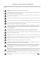
WARNINGS AND CAUTIONARY STATEMENTS
IMPORTANT: Failure to perform certain procedures or note certain conditions may impair the performance of this
product. For maximum safety and optimal performance, please read and follow the procedures and conditions listed
below.
IMPORTANT: Read and understand this manual before operating.
WARNING: SERVICING THE UNIT OR CHANGING THE BATTERIES MUST ONLY BE DONE IN
AN AREA KNOWN TO BE NONHAZARDOUS.
Prior to each day’s use, a bump test should be performed. If the instrument does not pass the bump test, a
full calibration is recommended.
Oxygen deficient atmospheres may cause combustible gas readings to be lower than actual concentrations.
Oxygen enriched atmospheres may cause combustible gas readings to be higher than actual concentrations.
Verify the calibration of the combustible gas sensor after any incident where the combustible gas content
has caused the instrument to display an over-range condition.
Silicone compound vapors or other known contaminants may affect the combustible gas sensor and cause
readings of combustible gas to be lower than actual gas concentrations. If the instrument has been used in
an area where silicone vapors were present, always calibrate the instrument before next use to ensure
accurate measurements.
Sensor openings and water barriers must be kept clean. Obstruction of the sensor openings and/or
contamination of the water barriers may cause readings to be lower than actual gas concentrations.
When in the hazardous area, connections to the battery charging or communications ports must be done in
accordance with this technical manual.
WARNING: Substitution of components may impair intrinsic safety and may cause an unsafe condition.
CAUTION: For safety reasons, this equipment must be operated and serviced by qualified personnel only.
Read and understand the instruction manual completely before operating or servicing.
CAUTION: High off-scale readings may indicate explosive concentration.
CAUTION: Any rapid up-scale reading followed by a declining or erratic readingmay indicate a gas
concentration beyond the upper scale limit which may be hazardous.
CAUTION: Before each day’s usage, sensitivity must be tested on a known concentration of pentane or
methane equivalent to 25%-50% of full scale concentration. Accuracy must be within -0% to +20% of
actual concentration. Accuracy may be corrected by referring to the zero/calibration section of the
instruction manual.
The BM 25A is CSA certified according to the Canadian Electrical Code for use in Class I, Division 1 and
Class I, Zone 1 Hazardous Locations within an ambient temperature range of -20°C to +55°C. CSA has
assessed only the combustible gas detection portion of this instrument for performance according to CSA
Standard C22.2 No. 152. applicable only when the instrument is used in the diffusion mode and has been
calibrated to 50% LEL CH4.
BM 25A with pump or with PID sensors or with infrared sensors for combustible gases detection is not
CSA certified.
7
8
I.
INTRODUCTION
The BM 25A is a portable gas detector that can be used in explosive gas atmospheres
according to directive ATEX 94/9/EC and the IECEx international certification system. It
provides simultaneous detection of up to 5 gases present in the air by means of sensors specific
to each risk to be evaluated (under-oxygenation, explosive or toxic gases).
1.
POWER
1.1. Power supply
The BM 25A is powered by an interchangeable and rechargeable battery pack.
Under normal operating conditions, and depending on the sensor configuration, operating runtime
varies between a minimum of 75 hours and a maximum of 170 hours (100 hours standard).
The power supply unit is a rechargeable NiMH 7V2 / 9AH battery pack.
1.1.1. Charging the battery pack
A lateral connector allows the battery pack (see the section on CHARGERS) to be charged without
dismantling.
1.1.2. Trickle charge
You can trickle charge your BM 25A continuously in a classified area to keep the charge level
constant (except in alarm conditions) for as long as needed by means of an intrinsically safe power
supply.
1.2. Memory saving
A lithium battery (non-rechargeable) ensures the storage of the BM 25A gas detector's specific data
(time/history), especially when the instrument is out of service (off mode) or without the battery
pack (main power supply).
This lithium battery has a maximum service life of two years without the main power supply
(battery discharged or internal switch in “off” position).
IMPORTANT: The instrument is approved for explosive atmosphere operations, only when it is
equipped with batteries of a type recommended by the manufacturer.
Switch instrument to “off” before any maintenance operation, such as battery replacement.
9
2.
SENSORS
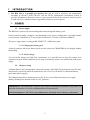
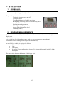
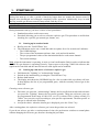
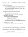
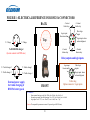
2.1. Sensor location (examples)
Sensors S7/S3
- SO2, ETO etc.
- CO2 IR
- Medium O2 sensor (2year lifetime)
Explosive gas sensor from 0 to 100% LEL.
2
1
Small format sensors
for toxic gases and
oxygen with 1 year
service
5
3
4
Medium sensors:
- O2 with 2-year lifetime
- CO/H2S, SO2, ETO etc.
- CO2 IR
1: explo LEL
2: tox/Ox mini
3: tox/Ox mini
4: tox/Ox medium
5: Big sensor (3 series type) or medium
Notes:
-
“Big sensors” are “3 or 7 series”. As an example: Compensated butane or hydrogen CO
sensor
In case sensors are present in slots 5 and 2, the sensor for slot 5 has priority and
deactivates the one for slot 2
The CO/H2S “combo” sensor shall be placed into slot #4.
Caution: Sensors’ slots and protection filters must be kept clean otherwise measurements
could be affected.
10
2.2. Combustible, toxic gases and oxygen sensors
The removable, interchangeable and intelligent sensor blocks are made of catalytic, electrochemical
or IR sensor and electronic components, including an “EEPROM” memory in which OLDHAM has
stored the sensor's specific characteristics (measuring range, various correction coefficients, STEL
and TWA alarms, date of manufacture, serial number, etc.).
Another parameter called the "wear rate" is used by the BM 25A to automatically determine the
optimal time to replace the sensor.
These sensor blocks, also called “intelligent blocks,” are plugged in as indicated in Chapter 2.1
above.
Caution: Silicon vapours or other “poisons” may have an adverse effect on explosive gas
detection sensors and distort measurements (under-estimated measurements).
If the instrument is used in poisoned atmospheres, calibrate it before its next use.
3.
DISPLAY UNIT
This is an LCD type display unit which lights up automatically in backlit mode in alarm or fault
conditions and the display can be reversed.
It shows:
-
4.
Five measurements for units and type of gas.
A calibration reminder
The date and time
Minimums-maximums
The mean STEL and TWA values
The remaining battery time (bar graph)
Operator identification (roundsman function)
Maintenance menus
Alarm transfers
VISUAL INDICATIONS
An indicator light (made of 20 ultra-bright LEDs) installed on top of the instrument indicates alarm
conditions and can be seen from all directions.
5.
AUDIBLE ALARMS
The operator is also warned when an alarm is triggered by two very powerful, built-in horns (103
dB @ 1m).
11
6.
SAMPLING
The BM 25A gas detector can be equipped with an internal electrical pump (not CSA certified) or
an external manual pump to measure gas concentrations in inaccessible locations or in locations
needing to be verified before access.
6.1. Operating instructions
The operator can:
Gas detector mode: place the gas detector in the working area and let the BM 25A
monitor the atmosphere.
Sampling mode: take regular measurements by means of a sampling system (manual
or electrical).
6.2. Electrical pumping system (not CSA certified)
The BM 25A gas detector can be optionally equipped with an integrated electrical pump, powered
directly from the gas detector’s battery pack. Pump drainage is between 18 and 25 1/h
NOTE: After each use of the electrical pump, check the watertightness by obstructing the end of
the sampling line until the draining alarm is triggered.
6.3. Manual pumping system
It consists of a cover, a horn bulb, a probe and a connecting line.
6.4. Different probes for manual and electrical pump
-
Rigid probe
Semi-rigid probe
Telescopic probe
CAUTION: Flexible probes, horn bulbs and certain rods are not antistatic. The operator
must take the necessary precautions to avoid electrostatic discharges, and, in any event, must
prevent any hazardous discharge through a metallic probe.
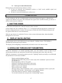
6.5. Gas detector mode
The BM 25A must be positioned vertically.
Depending on the type of gas to be detected or likely to be present, the instrument must be placed:
On the ground for detection of heavy gases (density > 1)
At medium height (approx. 1 m.) or in an outlet nozzle for a general detection of a
maximum of gases or for oxygen monitoring.
Optionally, the gas detector can also be used on a tripod to be more visible from
different areas.
12
7.
Communication Software COM 2100
This password-protected software is used to supervise and maintain the BM 25A gas detector:
Allows the display of gas measurements and grants access to parameters
Gives diagnostic assistance in case of failure
Helps programming of instrument and sensor channels
Allows management of options
Enables calibration of channels through an automated scrolling menu
Prints status and monitoring reports
Enables the management, display and printout of events and measurements stored
The BM 25A can be connected to a computer via a cable equipped with an infrared port.
Two versions are available: COM or USB port.
13
14
II. UTILIZATION
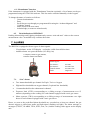
1.
KEYBOARD
Push buttons are "piezo" type with slight deformation.
They enable:
Turning the instrument on and off
The display mode
The acknowledgment of audible gas alarm
Backlighting of display (turns off automatically after 4
minutes)
Scrolling through parameters
Selecting menus during operation
Access to the Maintenance level
Validating (Enter)
2.
READING MEASUREMENTS
The gas content measured by each of the sensors "in service" can be seen on the alphanumeric
display unit.
It is divided into four independent zones, each one corresponding to a sensor channel.
A maximum of four readings can be displayed simultaneously.
In each field, the reading is displayed as follows:
Measurement
Unit
Gas symbol
In case of a 5-gas configuration, channel 5 is displayed alternately in field 3 of the
display unit.
The time is also shown at the bottom of the display unit.
15
3.
STARTING UP
IMPORTANT:
During first start-up, or after a period of inactivity longer than one month, the detector must be
charged, then discharged and recharged completely before operation. Additionally, keep in mind
that any portable gas detector must be bump tested each day of use.
REMINDER: Before starting up the BM 25A, check that the necessary sensors are connected.
During instrument start up, you have a choice of two procedures:
Standard procedure used in most cases
Procedure allowing you to select a reference explosive gas. This procedure is useful when
checking for a specific gas (natural gas, butane, etc.).
3.1. Starting up in standard mode
Briefly press the "On/Off/Enter" key:
The instrument carries out a visual and audio test phase for a few seconds and indicates:
- The OLDHAM logo
- The version of the instrument software, date, code and serial number
- The pre-programmed values of the alarm thresholds for each sensor channel
- The current readings
Note: when the instrument is operating, it emits a visual confirmation flash in order to indicate that
the BM 25A gas detector is operating correctly. Upon request or by using COM 2100 software, this
signal can be cancelled and the interval between each signal can be modified.
3.2. Starting up with choice of reference explosive gas
Hold down the "Lighting" or "Acknowledge" button
Switch on the instrument by pressing the “On/Off/Enter” key
Release both buttons
The display unit shows the OLDHAM logo for a few seconds while it performs self-tests.
It then displays the list of pre-programmed gases, with the currently selected gas in the
dark field.
Choosing a new reference gas:
Each time you press the “Acknowledge” button, the list scrolls downwards and each time
you press the “Lighting” button, the list scrolls upwards. Thirty-one reference gases are
pre-programmed in the range 0-100% LEL (or 0-5% volume CH4). A thirty-second (32)
“Other” lets you select a gas according to your specific requirements. The data specific to
that gas is entered in the workshop.
Accept the choice: when the chosen gas is displayed, press the “Enter” key.
After a testing phase, the explosive reference gas is now the gas that was selected.
If you do not select a gas after a certain amount of time, the gas detector switches to normal phase
without changing the reference gas, therefore aborting the procedure.
16
3.3. Start-up test and calibration due
During start-up, the instrument performs a self-test.
If tests are incorrect, the instrument switches to “fault” mode (audible signal and
continuous visual indication).
If tests are correct the instrument is ready to use.
CALIBRATION DUE
If, after starting up, the date of calibration has expired, the instrument triggers a calibration due
signal on the channel concerned. This calibration due signal can be cancelled and the gas detector is
still in use but must be calibrated.
4. SHUTTING DOWN
To shut down, hold down the "On/Off" button for three seconds.
On the display unit, the countdown "Stop 3, 2, 1" is displayed until the instrument is switched off.
In more recent gas detector versions, it is necessary to release the ON/OFF button, then press the
key again (follow the on-screen instructions).
When the gas detector is switched off, the set values (sensor adjustment data, alarm thresholds,
histogram, etc.) are saved.
5.
DISPLAY BACKLIGHTING
Measurements can be read in dark places by pressing the "Lighting" button. This lighting is
automatically deactivated after 4 minutes.
The display unit backlighting is automatically activated in case of an alarm or fault.
6. SCROLLING THROUGH SET PARAMETERS
When the instrument is in normal operating mode, you can consult a series of data on gas
measurements and also the instrument's internal data (remaining battery time, date and time).
While the instrument is in normal operation, press the "Lighting" button repeatedly to scroll through
the parameters for each sensor channel
-
Display unit backlighting and date
Measurement location and operator’s name (only with “roundsman” option activated:
see Section 6.1)
Remaining battery time in a bar graph
Indication of minimums detected by each sensor
Indication of maximums detected by each sensor
STEL of each “toxic” channel
TWA of each “toxic” channel
Message stating “Enter maintenance code”: to access maintenance menus, specify the
four-digit code with the “Acknowledge" and “Lighting” buttons.
If the code entered is incorrect: return to normal display
To exit the list before the end: press the “Acknowledge” button.
17
6.1 “Roundsman” function
If the instrument is equipped with the "Roundsman" function (optional), a list of names can be preprogrammed using the COM 2100 software. This list can be consulted manually via the keypad.
To change the name or location, as follows:
- Current location/name
- Enter
- Scroll down or up through pre-programmed list using the “Acknowledgment” and
“Lighting” button
- Enter (to select the new name)
- Acknowledge (to return to normal mode)
6.2
Re-initialization of MIN/MAX
Pushing Acknowledge and Lighting simultaneously restores “min and max” values to the current
measurement value. An audible beep confirms the action.
7. ALARMS
The BM 25A is equipped with two types of alarm signals:
- Visual alarms: on the LCD display + red strobe visible from all directions
- Audible alarms: two powerful horns (103 dB @ 1m)
Common LEDs for gas alarms,
transfer alarms and faults.
Alarm types:
Gas alarm 1:
Gas alarm 2:
Transfer alarm:
Fault:
7.1.
two-tone
two-tone fast
two-tone slow
single-tone
“Gas” alarms
Two instant thresholds per channel for Explo, Toxic or Oxygen
High and low thresholds on oxygen channel (2 optional low thresholds)
1 instant threshold on the catharometric channel.
Exposure limit (STEL) corresponding to a sliding average of measurements over 15
minutes (depending on the country) for each channel equipped with a toxic gas sensor.
Mean exposure (TWA) corresponding to a sliding average of measurements over eight
hours for each channel equipped with a toxic gas sensor.
Hence, as soon as the predefined alarm thresholds are exceeded on at least one channel, the gas
detector triggers a pulsed-tone audio and light signal (flashing red light). The alarm message or
messages (FAULT, ALARM, TWA, STEL, min., etc.) and the reading value appear on the display
unit.
18
In case of a gas alarm, the gas detector displays the maximum value detected until
acknowledgment.
7.2.
Fault alarms
Faults can be classified into two categories:
Faults concerning sensors: out of range, worn sensors, request for calibration in the case
of a major deviation during auto-adjustment. These faults generate messages on the
display unit, a visual alarm (steady red light) and a steady audible alarm.
Faults concerning the instrument itself (discharged batteries or electronic fault). The
corresponding fault message appears at the bottom of the display unit. It takes priority
over all other sensor-related messages.
Examples of information which may be brought to the user's attention:
Battery pre-alarm warning
The remaining battery life is at least 20 minutes. During this phase, measurements are
still provided, only the audible beep can be acknowledged.
Battery fault: The BM 25A is no longer measuring, fault is not acknowledgeable.
"> 100% LEL”. LEL sensor Overange.
This concerns only the combustible channel. When it happens,
- Display is frozen
- It is impossible to acknowledge the audible alarm
- The flashlight switches to the steady mode
- BM 25A powers down the LEL sensor in order to protect it.
Normal operating conditions can be restored by powering the BM 25A gas monitor down
and up (this operation must be performed outside the hazardous area).
“Out of Range” for toxic gas and oxygen
Negative fault (reading below -20% of the scale), acknowledged automatically
Positive fault (scale exceeded by 120%), must be manually acknowledged
7.3.
Gas alarms acknowledgement
7.3.1. Manual acknowledgement
Pressing the “Acknowledge” button stops the audible alarm, but the alarm indicator light flashes
until the measurement is lower than the programmed alarm threshold. As soon as the measurement
returns within the defined limits, the visual signal is automatically stopped.
In standard configurations, the audible alarm will be reactivated after two minutes if the gas level is
still above pre-defined limit(s) (this feature can be disengaged by request).
7.3.2. Automatic acknowledgement
By request, it is possible to automatically stop gas alarms as soon as the concerned gas levels
exceed the pre-defined threshold without pressing the “Acknowledge” button.
19
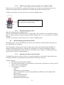
7.4.
Alarm transfer
The BM 25A has two “static” relays; one “gas alarm” relay common (in closing) for all channels
and one “failure” relay common in opening for all channels. The alarm relay is configured through
COM 2100.
The BM 25A is also equipped with two logic inputs (TOR):
-
1 input dedicated to remote acknowledgment
1 input dedicated to alarm triggering
These inputs are also configured through COM 2100.
Several gas detectors can be connected to each other in order to transfer an alarm from one gas
detector to another or to manually trigger an alarm.
2 relay outputs (default and gas) and 2 logic inputs
(remote acknowledged and alarm transfer)
IMPORTANT: Imperative parameters for relay outputs
AC
I Max 150 mA - V max 30V
DC
I Max 150 mA - V max 30 V
Caution: If the BM 25A gas detector is used in an explosive atmosphere, it is imperative to consider
output parameters, since contact must not impair the intrinsic safety of the gas detector. These
parameters are mentioned in the Special Instructions section for use in ATEX areas.
OLDHAM shall not, in any event, be liable for failure to follow regulations.
8. MEASUREMENTS
Caution: measurements can be affected by high or low oxygen concentrations. Any reading
rapidly changing from too high (exceeding the scale) to too low can in fact indicate a
hazardous gas level higher than the measurement scale.
8.1
Display of instantaneous readings
8.1.1.
Diffusion mode
All the instantaneous readings regarding gases are displayed in continuous mode.
The display unit is divided into four separate fields (quadrants).
Therefore, the operator can read:
The measurement
The measuring unit preceding the gas symbol
20
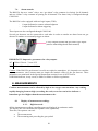
8.1.2
With electric pump systems (the pump is not certified by CSA)
Place the cover on the BM 25A as indicated and wait a few seconds to read measurements. Any
anomaly in the pump system is indicated by an audible alarm and on the display unit.
Caution: do not forget to remove the cover to return to diffusion mode.
Cover with pipe to connect the sampling
kit (electrical or manual pumps).
8.1.3
With manual pump systems
Place the calibration pipe as shown above.
Wait for measurements to stabilize before recording them. They could be over-estimated (explosive
gas) or under-estimated (oxygen) during manual pumping due to air movement and system
draining.
Caution: do not forget to remove the cover to return to diffusion mode.
8.2
Memorizing histogram measurements
Depending on the version, the BM 25A gas detector can memorize measurements so that they can
be restored later on a computer.
The "Histograms" function can be used to output values and events memorized by the BM 25A
during its operating period from a computer (a workstation, for example). Resetting of the data
contained in the histogram memory can only be performed with a computer. Switching off the gas
detector has no effect on memorized data.
8.2.1.
Operating principle: memorized items
The BM 25A stores sets of data as soon as it is started, and then in cyclic mode. Each of these sets
or threads (with their pre-programmed specifications) has the same structure.
A thread contains:
Information on measurement channels
The mean measurements of concentrations on each sensor in operation, over the period of
storage intervals (configurable)
The events on each channel:
- Resetting
- Fault
- Instantaneous or mean alarms
- Types of maintenance requested (programming, calibration, sensor replacement)
- Date and time
- Battery in discharged state
- Auto-adjustment request
- Maintenance function request.
21
8.2.2.
Memory capacity
The gas detector can store about 200,000 measurement points.
If the quantity of data to be stored exceeds the gas detector’s storage capacity, the oldest data are
lost.
8.2.3.
Data storage time
The data stored by the BM 25A are stored for two years if the instrument is no longer in service
(turned off or dead battery).
22
III. Special instructions for use in explosive
atmospheres or hazardous locations
Information in following paragraphs must be taken into account and followed by the person
responsible for the equipment installation site. Refer to the provisions of European ATEX Directive
1999/92/EC, the Canadian Electrical Code, or to the applicable local legislation, relevant to
improving safety protection and health of workers exposed to the risks of explosive atmospheres.
The installation and maintenance of the BM 25A should be performed according to the IEC 60079 14 and IEC 60079 – 17 standards, or via an OLDHAM authorized service center.
For intrinsically safe installations and especially for connections to the BM 25A, keep in mind that
the person responsible for the IS installation, called “the system designer,” must establish a system
document demonstrating that the whole system (BM 25A + cable + actuator) is Intrinsically Safe
(See standard IEC 60079-25 for the preparation of this document).
ATEX Essential Safety and Health requirements
comply with the following standards:
EN 50014 of June 1997 + Amendments 1 and 2
EN 50018 of November 2000 +amendment 1
EN 50020 of June 2002
EN 50284 of January 1999
EN 50303 of July 2000
IEC 60079-0 (Ed 4.0) / EN 60079-0
IEC 60079-1 (Ed 5.0) / EN 60079-1
IEC 60079-11 (Ed 4.0) / EN 60079-11
EN 60079-26
1.
Canadian Electrical Code requirements
comply with the following standards:
C22.2 No. 30
C22.2 No. 152
C22.2 No. 157
CAN/CSA-E79-0
CAN/CSA-E79-1
CAN/CSA-E79-11
ATEX areas and general rules
The BM 25A can be used in explosive atmospheres in Group II surface industries and Group I
mines containing firedamp.
The ambient temperature range for its use is from –20° C to + 55° C.
Depending on the type of sensors used on the instrument, categories covered by the gas detector
are:
- Surface industries: Category 2G, use in zones 1 or 2
- Mines containing firedamp: Category M2, use below a gas limit value
The following operations are prohibited in explosive atmospheres:
- Opening of the instrument: sensor cover or rear cover
- Recharging of batteries
- Link-up with a computer
All servicing, adjustment and maintenance operations must be performed by duly approved
personnel.
In order to avoid any risk of explosion by electrostatic discharges, the display unit glass and
indicator light must be cleaned only with a damp cloth. The battery pack must be replaced by the
original part specified by the manufacturer – OLDHAM P/N 6311082.
23
2.
ATEX zones: input/output parameters
2.1. Gas detector recharge connector
It is recommended that the charger provided by OLDHAM be used outside of the ATEX area.
When the recharging is done by a charger other than the one provided by OLDHAM, its
characteristics must not exceed a voltage of 30 VDC and a current of 30 A.
2.2. Connector for alarm outputs / fault and digital TOR inputs
The characteristics of static relay contacts inputs opto isolated and built into the gas detector are:
U in = 30 V max
I in = 150 mA max
The output characteristics of TOR digital inputs built into the gas detector are:
U out = 5 V max
I out = 50 mA max
L out = 8 mH
C out = 7 µF
Only zero voltage circuits can connect to the digital inputs, i.e. Uin = 0V and Iin = 0A.
Caution: the two previous circuits are separate intrinsic circuits. The cables connected to the ends of
these circuits must comply with the requirements for intrinsically safe circuit wiring: type of cables,
insulation voltage, insulation, linear capacity and inductance. Refer to national and international
standards, for example EN 60079-14.
A system log should be established by the person responsible for the installation as explained above.
2.3. External power connector
External power sources for maintenance of the battery pack must be intrinsic safety power sources
and must be compatible with the following input characteristics of the BM 25A:
U in = 30 V
I in = 160 mA
C in = 0 µF
L in = 0 mH
It is possible to connect two external power supplies on the connector in accordance with the rules
specified in the previous paragraph.
2.4. Connector accessories / options
Figure 1 shows the different connection options for the BM 25A. The connectors are located on the
sides of the gas detector.
Note: Unused connectors must be equipped with their protective cap.
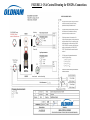
3.
CSA hazardous locations: input/output parameters
The control drawing shown in Figure 2 defines the CSA approved electrical parameters permitted
for the interconnection of the BM 25A to other circuits or apparatus while the instrument is situated
in a hazardous location
24
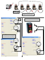
FIGURE 1: ELECTRICAL REFERENCE FOR BM 25A CONNECTORS
- Contact
BACK
Fault relay
3
V+ Charge
4
Logic input:
Alarm transfer
2
1
Top
V- Charge
3
2
4
7
1
To OLDHAM charger
(do not connect in ATEX area)
+ Contact
Fault relay
Mass logic
inputs
5
6
1
Logic input: alarm
acknowledgment
+ Contact
Alarm relay
- Contact
Alarm relay
Relay outputs and logic inputs
V+ Trickle charge 2
3
2
V- Trickle charge 2
4
1
Logic input:
Alarm transfer
V- Trickle charge 1
4
3 7 5
2
1
6
V+ Trickle charge 1
External power supply
for trickle charging of
BM 25A battery pack
FRONT
25
Logic input: alarm
acknowledgment
Yellow ring
Option connector = logic inputs
SI Parameters:
- Alarm contact Static type relay Vin=30Vdc, Iin=150 mA, Lin=0 et Cin=0
- External power supply for trickle charging U in =30V, I in=160 mA, Lin=0 et Cin=0
- Logic input U out = 5 V, I out = 50 mA, L out = 8 mH, C out = 7 µF
Caution: The responsible person must create an IS system log (see BM 25A note)
Mass logic
inputs
OUT
IN
Alarm
Straight-forward alarm transfer
Manual call point connection
out
3
4
7
2
5
1
3
6
7
4
2
5
1
6
IN
Connection between two BM 25A
3
7
4
2
5
1
6
3
7
4
2
5
1
3
2
5
7
1
6
4
6
3
7
4
2
5
1
26
6
FIGURE 2: CSA Control Drawing for BM 25A Connections
27
4.
Marking
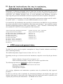
4.4.1 ATEX and IEC Ex
OLDHAM ARRAS
CE 0080
BM 25A
IP66
Ambient T : -20° C +55° C
II 2G / I M2
Ex ia d IIC T4 Ex ia d I
INERIS 05ATEX0044
IECEX INE 06.0002X
Do not open in explosive atmospheres
Potentially hazardous electrostatic charges – see instructions
serial number
manufacture year
4.4.2 CSA
OLDHAM
Model: BM 25A; P/N: 6514872
CSA logo
LR104516
Serial number
Exia intrinsic safety
Ex ia d IIC T4; Class I, Division 1, Group A B C D; T4
C22.2 No. 152
BM 25A with pump or with PID sensors or with infrared sensors for combustible gases detection is not
CSA certified.
28
IV. M AINTENANCE
Gas detectors are above all safety instruments. Recognizing this fact, OLDHAM Corporation
recommends that a functional (bump) test be performed on every portable gas detector prior to
each use. A functional test involves the injection of a gas of sufficient concentration at the sensor
level to trigger pre-set alarms. This test does not, in any event, replace a full calibration of the
sensor.
OLDHAM further recommends that a full instrument calibration be performed using a known
and certified concentration of calibration gas monthly to ensure accuracy of the instrument.*
If a gas detector does not respond correctly to a gas test, a full calibration with a standard gas is
mandatory.
These recommendations are consistent with applicable industry safety protocols and with the
standards and directives relative to the safety of industrial sites. Furthermore, OLDHAM is not
responsible for procedures implemented on a site.
IMPORTANT: The BM 25As are programmed by the manufacturer for an automatic
maintenance check after twelve months if the calibration has not been done ("Calibration due"
appears on screen).
The metrological certification of the BM 25A by the CSA (Canadian Standards Association)
according to standard CSA C22.2 No. 152 concerns only the “sensor for detection of explosive
gas”) CSA No. 152 standard requires calibration of the instrument with a concentration of
"methane/CH4" of 50% LEL, and an operating temperature between 0 and 40°C.
The operations explained in this chapter must be performed by authorized, qualified
personnel only as they could adversely affect detection safety.
1.
ACCESS TO MAINTENANCE MENUS
With the BM 25A in operation, menus can be accessed in the following manner:
Scroll to parameters with a central key until a request for a standard access code 0018
is displayed
Scroll to each digit with the “Lighting” button, choose the figure with the
“Acknowledge” button and validate access code with the “Enter” key.
The list of available menus is then displayed:
-
Programming
Calibration
Auto-zero
Date and time
Exit
1.1. Channel settings
This is used to:
Select the channel to be programmed
Switch the selected channel On and Off
Inform the operator of the type of sensor for the measuring range
29
In the case of an explosive sensor, select the type of reference gas from 31 pre-selected
gases or enter the coefficient of a 32nd gas and program instantaneous thresholds
When an oxygen sensor is used, to program the “min” and “max” alarm thresholds if
this option was selected
When a toxic gas sensor is used, to program instantaneous thresholds
When a catharometric sensor is used, to program low instantaneous thresholds
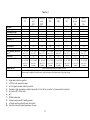
1.1.1. List of pre-programmed “explo" gases and coefficients
The combustible gases sensor used in the BM 25A is a “Wheatstone bridge” sensor
type. The coefficients are given for information in relation to a CH4 scale with LEL =
5.0% (the BM 25A already takes them automatically into consideration during the
calibrations / range changes).
Molecular
Vapour
Coef. /
density
CH4
gas calibr.
(French)
13%
2.1
1.70
But/Prop
ACO
1.5%
100%
0.9
1.3
But/Prop
ACY
C4H10
1.5%
8.5%
2.0
2.13
But/Prop
BUT
Ethanol
C2H6O
3.3%
19.0%
1.6
1.50
But/Prop
ETA
Ethylene
C2H4
2.7%
34.0%
0.98
1.30
But/Prop
ETY
Prop+But
1.65%
9.0%
1.85
1.90
But/Prop
LPG
CH4
5.0%
15.0%
0.55
1.05
CH4
GNT
C6H14
1.2%
7.4%
3.0
2.30
But/Prop
HEX
H2
4.0%
75.6%
0.069
0.89
But/Prop
H2
C3H8O
2.15%
13.5%
2.1
1.9
But/Prop
ISP
Methane3
CH4
5.0%
4.4%
15.0%
0.55
1.00
1.14
CH4
CH4
Methanol
CH3OH
5.5%
44.0%
1.1
1.175
But/Prop
MTL
Pentane
C5H12
1.4%
8.0%
2.5
2.08
But/Prop
PNT
Propane
C3H8
2.0%
9.5%
1.6
1.77
But/Prop
PRO
Propylene
C3H6
2.0 %
11.7 %
1.5
1.2
But/Prop
PRY
Toluene
C7H8
1.2%
7.0%
3.1
2.10
But/Prop
TOL
Xylene
C8H10
1.0%
7.6%
3.7
2.5
But/Prop
XYL
LEL1
LSE2
C3H6O
2.15%
Acetylene
C2H2
Butane
Gas
Acetone
L.P.G.
Natural gas
Hexane
Hydrogen
Isopropanol
formula
Suggested Abbreviation
1
Lower flammable limit
Upper flammable limit
3
The LEL adopted value for methane varies by country, there are two different CH4
ranges (LEL = 4.4% and 5.0% = LEL) to consider.
2
If the explosive gas that you want to detect is not in the list above, you can use the window
"other" by selecting a coefficient given by OLDHAM (contact us).
30
1.2. Sensor calibration menu
This menu is used to regularly calibrate the sensors connected to the instrument.
Calibration consists of adjusting the zero of the clean air sensor (free of gas which may be
detected by the BM 25A) and adjusting sensitivity with a standard gas of known characteristics.
Flow rate of the standard gas rate must be 601/h.
1.3. Auto-zero menu
This menu lets you adjust the "zero" of each sensor used in the BM 25A automatically and
simultaneously.
Caution: this menu must be used in clean air only!
1.4. Date and time management menu
This menu is used to update the internal calendar and clock of the gas detector.
These data are used to define time scales, especially when the measurements stored in memory
(min., max., STEL and TWA) are printed out or downloaded to an external microcomputer.
Loss of date and time
The electronic circuits for the date and time are supplied with power by a specific lithium battery
when the main battery is flat or when the device is switched off.
This lithium battery has an estimated service life of 2 years.
When this battery is low, operator is notified with a "low battery" message before losing all
stored data. Battery must then be replaced.
CAUTION: This operation is to be performed by OLDHAM or OLDHAM-approved
personnel only.
1.5. Exit menu
To return to normal operating mode.
31
32
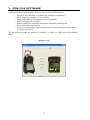
V. COM 2100 SOFTWARE
COM 2100 software ensures the gas detector's supervision and maintenance:
-
Display in uncoded mode of readings and parameters on channels
Gives diagnostic assistance in case of failure
Helps programming of instrument and sensor channels
Allows management of options
Enables calibration of channels through an automated scrolling menu
Prints status and control reports
Enables the management, display and printout of events and measurements stored
Is password protected
The link between the BM 25A and the PC is made by a “COM” or “USB” infrared port adaptor
cable.
Opening screen
33
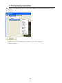
1. Instrument connection
Note: COM 2100 automatically detects a MX 2100 or BM 25A connection and relevant screens
are displayed.
-
Program necessary communication parameters (port, speed, language)
Click on “connect”
34
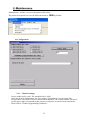
2. Maintenance
"Maintenance" window: access to the menus listed below
The password required to access the different menus is 1000 by default.
2.1.Configuration
2.1.1. Channel settings
-
-
Access authorized by code. The standard code is 1000.
Select the desired configuration: the first column “Switching on" (on the upper left)
corresponds to activated or inactive measurement channels. The second column “Presence"
(on the upper right) corresponds to the presence or absence of sensors on the instrument.
Then click on “Channel programming validation.”
35
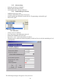
2.1.2. Alarm settings
-
Select the tab choice of channel
Modify alarm threshold values
And confirm with “Alarms validation”
2.1.3. Combustible gas selection
-
Authorized access by code
Change combustible gas name if necessary
Choose another gas from the list and click on "Programming combustible gas"
Then click “Quit”
2.2.Calibration
-
Choose sensor to calibrate
Set, if necessary, the maintenance interval
Indicate the standard gas level used
Proceed to “zero” as per instructions of software
Then proceed to sensitivity without forgetting to indicate first (in red) the standard gas level
to be injected
The following messages will appear; if not, start over:
36
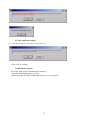
2.3.Time and Date settings
You can update the BM 25A clock directly with the PC clock.
-
Click “OK” to validate
2.4.Monitoring reports
-
Fill in the fields (user's information for instance)
Create the monitoring report (.ctr file)
Open it from the PC (from COM 2100 folders) to view or print it
37
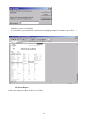
Examples:
- Click “Read only”
38
-
Printable version of certificate
It is possible to personalize this document by changing headers for instance (your firm ...)
2.5.Status Report
Follow the same procedure as above (.etx files).
39
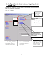
3. Configuration of alarm relay and logic inputs for
the BM 25A:
-
Fill in the table displayed on screen by clicking on the appropriate windows according to
alarm relay use and logic inputs needed
-
Click “OK” to validate
For activation of
internal alarm
relay by an
external alarm
Logic
input of
alarms
Alarm type, visual
indicators:
- Alarm 1 = low speed
- Alarm 2 = high
speed
- Transferred alarm =
very low speed
Logic
input of
acknowle
dgment
Local acknowledgment = to
acknowledge a manually
transferred alarm from BM
25A keyboard
-
programming column for
activation of alarm relays
- programming column for
logic inputs
40
Remote acknowledgment = to acknowledge a BM 25A alarm
by a transfer button
(closing of contact)
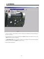
4. SCREENS
-
"Screens" window: displays history, faults, readings and configuration of the instrument at
the time of purchase
-
The maintenance access code for the BM 25A (0018 standard) and software access code
(1000 standard) can also be modified
-
A roundsman list can be created for further use by operators. This provides histograms
related to a date/time and a name (location or user)
-
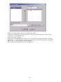
How to create a name list?
41
-
-
Write a new name under “Enter new Location/User name”
Validate by clicking “Save new Location/User name”. It will automatically appear in the
“Locations / Users available” box
Click on the name (in blue)
In the area on the right titled “Locations / Users list saved in instrument memory” click the
right arrow” “>” key. This way, you can navigate names or the full list from left to right and
right to left, by using the single or double arrows
Click “OK” to download the new list to the BM 25A
42
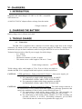
VI. CHARGERS
1. INTRODUCTION
Integrated and smart charger, 12 VDC to 30 VDC, compatible
with vehicle use.
A 100VAC/230VAC adaptor allows recharge from the mains.
Charger connector
2. CHARGING THE BATTERY
Battery charge time is 4 hours and a half.
3. TRICKLE CHARGE
3.1. Connection
The BM 25A is supplied with a connector for trickle charge (right next to the charger
connector). By means of one or two intrinsic safety power supplies, the battery’s charge can be
maintained (except in alarm conditions) while leaving the BM 25A in use in a classified area.
Technical characteristics of the IS power supply for trickle charge:
- Io 160mA
- Pmax= 1.2W
- Maximum resistance of cable=16 ohms
- This means a max. cable length of 500 m to 1.5 mm²
Trickle charge connector
Trickle charge cables with lengths of 25 m, 50 m or 100 m are single or double depending on
whether the BM 25A is equipped with both explosive and infrared sensors.
CAUTION:
ATEX applications – Refer to Section III, Clause 2. Only power supply, p/n
6111303, provided by OLDHAM can be used.
a) For connection to single trickle charge supply, use BLUE
INSTRUMENTATION CABLE TYPE 01 IP 09 EGSF.
b) For connection to dual trickle charge supplies, use BLUE
INSTRUMENTATION CABLE TYPE 03 IP 05 EISF.
CAUTION: CSA applications – Refer to Section III, Clause 3. The trickle charge connector is
for connection to CSA Certified Associated Apparatus with entity parameters that
satisfy the conditions of Note 4 in the control drawing (Figure 2).
a) For connection to single trickle charge supply, use cable assembly p/n
6315866, 6315867, or 6315868 and mating connector, p/n 6153064.
b) For connection to dual trickle charge supplies, use cable assembly p/n
6315869, 6315870, or 6315871, and mating connector, p/n 6153064.
Cable shields must be connected to ground at the supply end.
43
44
VII. DISPOS AL
For the preservation, protection and improvement of environmental quality,
and for the protection of human health and the prudent and rational utilization
of natural resources, the BM 25A must be disposed of separately from
electronic equipment and cannot be disposed of with normal household waste.
The user therefore has an obligation to separate the BM 25A from other waste
to ensure that it is recycled safely for the environment. For further details on
existing collection sites, contact the local administration or seller of the
product.
VIII.
ACCESSORIES
Part Number
Description
6511154
WCHMUBM
6321390
WLOG210
WLOGUSB
6314588
6314583
6331159
6327920
6327919
6327918
6327921
6327922
6327923
6327924
6321388
Charger 220 VAC for BM 25A / Charging time 4 hrs. 30 min.
Wall charger for BM 25A
Support for wall charger BM 25A
Software kit COM 2100 with infrared cord /COM
Software kit COM 2100 with infrared cord /USB
Connection cord IR / USB
Connection cord IR / COM
Gas calibration and sampling (manual) pipe
Sampling kit with rigid pump rod
Sampling kit with semi-rigid pump rod (not for use in classified areas)
Sampling kit with telescopic pump rod
Manual sampling kit with crystal tube (4 m)
Manual sampling kit with telescopic rod
Manual sampling kit with semi-rigid rod (not for use in classified areas)
Manual sampling kit with rigid rod
Tripod
Trickle Charge Kits
6311085
6311089
6311093
6311094
6311095
6311096
Trickle charge kit, single, length: 25m
Trickle charge kit, single, length: 50m
Trickle charge kit, single, length: 100m
Trickle charge kit, dual, length: 25m
Trickle charge kit, dual, length: 50m
Trickle charge kit, dual, length: 100m
Alarm Transfer
6314601
Connector Kit for Alarm Transfer including two connectors (one male and one
female)
45
46
IX. SP ARE P ARTS
Part Number
Combustible sensors
6313969
Sensor for Combustible gases, 0-100% LEL
Medium sensors
6313780
6313823
6313818
6313857
6313843
6313821
6313819
6313822
6313841
O2 sensor (medium type) (lifetime 2 years)
COMBO CO / H2S sensor
CO2 sensor, 0-5% vol.
NO2 sensor, 30 ppm
Cl2 sensor, 10 ppm
ETO sensor, 0-30 ppm
SO2 sensor, 0-30 ppm
SO2 sensor, 0-100 ppm
ClO2 sensor, 0-3 ppm
Mini Tox / O2 sensors
6313817
6313787
6313826
6313788
6313816
6313799
6313800
6313801
6313802
6313803
6313804
6313805
6313806
6313807
6313808
6313809
6313810
6313811
6313812
6313820
6313879
O2 sensor (lifetime 1 year minimum)
CO sensor, 0-1000 ppm
CO sensor, 0-2000 ppm
H2S sensor, 0-100 ppm
H2S sensor, 0-30 ppm, special for hydrocarbons
NH3 sensor, 0100 ppm
NH3 sensor, 0-1000 ppm
NO2 sensor, 0-30 ppm
NO sensor, 0-300 ppm
H2 sensor, 0-2000 ppm
HCl sensor, 0-30.0 ppm
HCN sensor, 0-30.0 ppm
HF sensor, 0-10 ppm
O3 (ozone) sensor, 0-1 ppm
SIH4 (silane) sensor, 0-50 ppm
Cl2 sensor, 0-10.0 ppm
PH3 (phosphine) sensor, 0-1 ppm
AsH3 (arsine) sensor, 0-1 ppm
COCl2 (phosgene), 0-1 ppm
F2 sensor, 0-1 ppm
N2H4 sensor, 0-1ppm
5th Position (not CSA certified)
6313998
6314065
6314064
6314087
6314088
6314089
6314090
6314092
PID isobutylene sensor
CH4 IR sensor, 0-100% LEL (4.4% vol)
CH4 IR sensor, 0-100% LEL (5.0% vol)
C3H8 IR sensor, 0-100% LEL
C4H10 IR sensor, 0-100% LEL
Isobutane IR sensor, 0-100% LEL
LPG IR sensor, 0-100% LEL
CH4 IR sensor, 0-100% vol
Note: This list is not exhaustive and may be modified.
Sensors must be stored in a cool place (5°C).
47
Part Number
Combustible sensors
6313832
Batch of fake TOX/O2/COMB sensors
6111303
IS power supply only
6153027
connector for IS power cable
48
X. TECHNICAL CHAR ACTERISTICS
1. DESCRIPTION
Manufacturer: OLDHAM
Function:
Multi-risk gas detector
Type:
BM 25A
Configuration:
One to four sensors (explosive, electrochemical, infrared (CO2))
Gases detected:
Explosive gases, toxic gases and oxygen
Measurement:
Continuous on all sensors in operation
Sensors:
Intelligent, precalibrated, interchangeable units
Automatic recognition by the BM 25A by means of EEPROM
Display unit:
Graphic LCD
Messages in uncoded mode, with backlighting
“Flip-Flop” function
Display lighting:
With time switch upon request, automatic for alarm or fault
Sensor faults
Indication by indicator light
Message in uncoded mode
Corresponding display "frozen". Other channels operational
Continuous general audible and visual alarm
Battery fault:
Display in uncoded mode
Continuous general audible and visual alarm
Operating check:
Self-test on power-up
Visual signal every 2 minutes (factory)
Display of measured values in uncoded mode
Alarm thresholds:
LEL: 2 adjustable instantaneous thresholds in 0-60 % LEL range
Oxygen: two adjustable instantaneous thresholds over the sensor's whole measuring scale
(over-oxygenation and under-oxygenation) or two optional under-oxygenation thresholds
49
Toxic (by sensor): two adjustable instantaneous thresholds over the whole range
- One TWA threshold
- One STEL threshold
Alarm sig
nals:
General audible and visual alarm (display unit, indicator light)
Display in uncoded mode of the fault or alarm for the channel concerned
Inputs/Outputs:
RS232 link by infrared
On PC, maintenance and supervision software, EXCEL database
Alarm relay output
Fault relay output
One logic input for alarm trigger
One logic output for remote acknowledgment
Ancillary software packages:
Maintenance software COM 2100
Power supply:
NiMH rechargeable battery pack
Battery life (except in alarm conditions):
70 hours with 1 catalytic and CO2 sensors
100 hours with 1 catalytic + Tox sensors
170 hours with Tox sensors only
Charging time:
4 hours 30 minutes
Ingress Protection:
IP66 certified by Notified Body (INERIS)
Weight:
6.85kg
Dimensions:
H470 x L180 x P190 mm
Electromagnetic Compatibility:
compliant with standard EN 50270 according to Electromagnetic Compatibility Directive
89/336/EEC
50
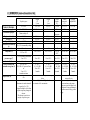
2. SENSORS (non-exhaustive list)
Explosive gases
Sensor reference
Standard range (1)
Measurement principle
6 313 969
0 - 100% LEL
Thermo-catalytic 4L
1 % LEL
Display resolution (1)
2
Accuracy (2)
± 1 % LEL
Repeatability (3)
Deviation of zero/sensitivity
0,5% / 2,5% from monthly reading
(4)
< 20 seconds
Response time (5) (sec)
Temperature (6)
-20°C to +50°C
Oxygen
O2
2 years
6 313 780
Oxygen
O2
1 year
6 313 817
Carbon
dioxide
CO2
6 313 818
Carbon
monoxide
CO
6 313 787
Hydrogen
sulphide H2S
2 - 30% volume
Electrochemical
2 – 30% volume
Electrochemical
1000
Electrochemical
100
Electrochemical
0.1% v/v
0.3% v/v
0.1% v/v
0.2 / 2
0.1% v/v
0.3% v/v
0.1% v/v
0.2 / 2
0 - 5% v/v
Infrared
absorption
0.1% v/v
0.2% v/v
0.1% v/v
0.2 / 2
1
15
1
0.5 / 1.5
1
3
1
0.5 / 2.5
< 10
-20°C to +40°C
< 10
-20°C to +40°C
< 30
-20°C to +40°C
< 25
-20°C to +40°C
10 – 95 % RH
1 bar ± 20 %
10 – 95 % RH
1 bar ± 20 %
36 months
4 – 20 °C
10 – 60 % RH
1 bar ± 10 %
2 months
36 months
4 – 20 °C
10 – 60 % RH
1 bar ± 10 %
2 months
Relative humidity and
pressure range (7)
0 – 95 % RH without condensation
1 bar ± 20 %
10 – 95 % RH
1 bar ± 20 %
10 – 95 % RH
1 bar ± 20 %
< 30
-10°C to
+40°C
10 – 95 % RH
1 bar ± 20 %
Service life (8)
Storage conditions and
maximum storage time (9)
48 months
-40°C to +40 °C
10%< HR< 60 % protected from
air
1 bar ± 10 %
6 months maximum
28 months
4 – 20 °C
10 – 60 % RH
1 bar ± 10 %
3 months
16 months
4 – 20 °C
10 – 60 % RH
1 bar ± 10 %
3 months
60 months
0 – 40 °C
10 – 60 % RH
1 bar ± 20 %
6 months
Response time (10)
Notes:
Sensors functional immediately after start up of
device
- Presence of high levels of CO2 can lead to an
- Measurement is underestimated if over estimation of O2 concentration
oxygen level is < 10%
- Exposure to high levels of silicon
or sulphur vapors may damage the
detector.
- The detector is sensitive to a
majority of explosive gases
<30 s
120 s
6 313 788
Sensors functional immediately after
start up of device
- Exposure to high levels of organic
solvents can damage the sensors
- Exposure to gases at higher levels
than detector’s range can damage it.
Recalibrate sensors if they go out of
range
Table No. 2
Reference
Standard range (1)
Measurement principle
Display resolution (1)
Accuracy (2)
Repeatability (3)
Deviation of zero/sensitivity (4)
Response time (5)
Temperature (6)
Relative humidity and pressure
range (7)
Service life (8)
Storage conditions (9)
Warm-up time (10)
Notes:
12245678910-
Chlorine
C12
Hydrochloride
acid
HCl
Hydrocyanic
acid
HCN
Ammonia
NH3
Ammonia
NH3
Nitric oxide
NO
Nitrogen
dioxide
NO2
Sulphur
Dioxide
SO2
6 313 809
10
Electrochemical
0.1
0.25
2
0.5 / 5
6 313 804
30
Electrochemical
0.1
1
2
0.5 / 5
6 313 805
10
Electrochemical
0.1
0.25
2
0.5 / 5
6 313 799
100
Electrochemical
1
5
2
1/2
6 313 800
1000
Electrochemical
1
30
2
1/2
6 313 802
300
Electrochemical
1
10
1
0.5 / 3
6 313 801
30
Electrochemical
1
1
1
0.5 / 5
6 313 819
30
Electrochemical
1
1
1
0.5 / 2
< 60
-20 to +40
10 – 90 % RH
1 bar ± 20 %
30
4 – 20 °C
10 – 60 % RH
1 bar ± 10 %
2 months
< 80
-20 to +40
15 – 95 % RH
1 bar ± 20 %
24
4 – 20 °C
10 – 60 % RH
1 bar ± 10 %
2 months
< 60
< 60
< 60
< 30
-20 to +40
-20 to +40
-20 to +40
-15 to +40
15 – 95 % RH
15 – 90 % RH
15 – 90 % RH
20 – 90 % RH
1 bar ± 20 %
1 bar ± 10 %
1 bar ± 10 %
1 bar ± 20 %
24
24
24
30
4 – 20 °C
4 – 20 °C
4 – 20 °C
4 – 20 °C
10 – 60 % RH
10 – 60 % RH
10 – 60 % RH
10 – 60 % RH
1 bar ± 10 %
1 bar ± 10 %
1 bar ± 10 %
1 bar ± 10 %
2 months
2 months
2 months
2 months
Sensors functional immediately after start up of device
- Exposure to high levels of organic solvents can damage the sensors
- Exposure to gases at higher levels than detector’s range can damage it. Recalibrate sensors if they go out of range
< 30
-20 to +40
15 – 90 % RH
1 bar ± 20 %
40
4 – 20 °C
10 – 60 % RH
1 bar ± 10 %
2 months
< 60
-20 to +50
15 – 90 % RH
1 bar ± 10 %
30
4 – 20 °C
10 – 60 % RH
1 bar ± 10 %
2 months
In ppm unless otherwise specified
At 50% of scale (same unit as range)
As % of signal read unless otherwise specified
Nominative values in normal use conditions per month as % of scale for zero and as % of measurement for sensitivity
In seconds at 90% of final value
In °C
Without condensation
Average noted per month 12 month guarantee
All sensors must be protected from air when stored
Time from start-up for optimal performance of sensor
52
XI. EC DECLAR ATION OF CONFORMITY
The Fixed Gas Detection People
EUROPEAN PLANT AND OFFICES
Z.I. Est – rue Orfila CS 20417 – 62027 Arras Cedex FRANCE
Tél: +33 (0)3 21 60 80 80 – Fax: +33 (0)3 21 60 80 00
Website: http://www.oldhamgas.com
AMERICAS
Tel: +1-713-559-9280
Fax: +1-281-292-2860
[email protected]
ASIA PACIFIC
Tel: +86-21-5899-3279
Fax: +86-21-5899-3280
[email protected]
EUROPE
Tel: +33-321-608-080
Fax: +33-321-608-000
[email protected]