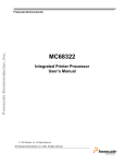
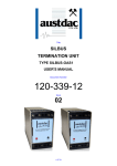
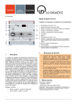
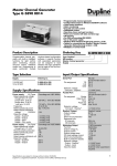
1
Title
4 CHANNEL ANALOGUE
RECEIVER
TYPE SILBUS-RX4A
USER'S MANUAL
Document Number
120-208-12
Issue
02
1 OF 24
REVISION CONTROL
02
Fix specs, add prog info
2010.02.02
PB’
PB’
JY
01
Original
2009.02.10
PB’
PB’
JY
Issue
Details
Date
Written
Designed
Approved
Austdac Pty Ltd
Unit 1 / 4 Packard Avenue
Castle Hill NSW 2154
Australia
PO Box 6486
Baulkham Hills Business Centre
NSW 2153
Australia
Phone: + 61 2 8851 5000
Fax: + 61 2 9899 2490
Website: www.austdac.com.au
Austdac Inc.
455 Lowries Run Rd,
Pittsburgh, PA 15237
USA
Phone: +1 888 254 9155
Fax: +1 412 635 0179
Copyright 2009-01-19
This document remains the property of Austdac Pty. Ltd. It is subject to its recall and must not be
reproduced in part or whole or its contents divulged to third parties without prior written approval
from Austdac Pty Ltd.
4 CHANNEL ANALOGUE RECEIVER
TYPE SILBUS-RX4A USER'S MANUAL
2 OF 24
120-208-12
Is s u e : 0 2
TABLE OF CONTENTS
REVISION CONTROL ...................................................................................................................... 2
TABLE OF CONTENTS.................................................................................................................... 3
PHOTOGRAPHS .............................................................................................................................. 4
TABLES ............................................................................................................................................ 4
FIGURES .......................................................................................................................................... 4
1 GENERAL DESCRIPTION ............................................................................................................ 5
2 FRONT PANEL LAYOUT .............................................................................................................. 5
3 THEORY OF OPERATION............................................................................................................ 6
4 OPERATING INSTRUCTIONS...................................................................................................... 8
5 CONFIGURATION......................................................................................................................... 8
5.1 CONSOLE PORT OPERATION ............................................................................................. 9
5.2 HELP COMMAND................................................................................................................. 10
5.3 REPEAT COMMAND............................................................................................................ 10
5.4 VERSION COMMAND .......................................................................................................... 11
5.5 STACK COMMAND .............................................................................................................. 11
5.6 SILBUS MAP COMMAND..................................................................................................... 12
5.7 SILBUS STATUS COMMAND .............................................................................................. 12
5.8 SILBUS GET COMMAND ..................................................................................................... 12
5.9 ANALOGUE OUTPUT ADDRESS COMMAND .................................................................... 13
5.10 FAULT ADDRESS COMMAND .......................................................................................... 14
5.11 FAULT LEVEL COMMAND................................................................................................. 15
5.12 fault hysteresis command ................................................................................................... 15
5.13 analogue SELECT command.............................................................................................. 16
5.14 analogue output command.................................................................................................. 16
5.15 fastlink marker command .................................................................................................... 17
6 TERMINATIONS AND CONNECTIONS...................................................................................... 18
6.1 ANALOGUE OUTPUT PORTS ............................................................................................. 18
6.2 POWER INPUT PORT.......................................................................................................... 19
6.3 SILBUS NETWORK PORT ................................................................................................... 19
7 CERTIFICATION ......................................................................................................................... 20
7.1 INSTALLATION CONFIGURATION 1 .................................................................................. 21
7.2 INSTALLATION CONFIGURATION 2 .................................................................................. 22
8 SOFTWARE REVISION AND DISPLAY...................................................................................... 23
9 SPECIFICATIONS ....................................................................................................................... 24
4 CHANNEL ANALOGUE RECEIVER
TYPE SILBUS-RX4A USER'S MANUAL
3 OF 24
120-208-12
Is s u e : 0 2
PHOTOGRAPHS
Photograph 1 SILBUS-RX4A front panel .......................................................................................... 5
Photograph 2 Access to console port and programming switch ....................................................... 6
Photograph 3 Laptop connected to console port via MEAN1 interface ............................................ 9
TABLES
Table 1 Status LED flash sequence meanings ................................................................................. 8
Table 2 SILBUS-RX4A Configuration record .................................................................................. 17
Table 3 Analogue output termination details................................................................................... 19
Table 4 Power input port termination details................................................................................... 19
Table 5 SILBUS network port termination details ........................................................................... 19
Table 6 Installation configuration 1 entity parameters .................................................................... 21
Table 7 Installation configuration 2 entity parameters .................................................................... 22
Table 8 SILBUS-RX4A Software revision history ........................................................................... 23
FIGURES
Figure 1 SIBUS-RX4A Connection diagram ................................................................................... 18
Figure 2 SILBUS-RX4A segregation and isolation levels ............................................................... 20
Figure 3 Installation configuration 1 ................................................................................................ 21
Figure 4 Installation configuration 2 ................................................................................................ 22
4 CHANNEL ANALOGUE RECEIVER
TYPE SILBUS-RX4A USER'S MANUAL
4 OF 24
120-208-12
Is s u e : 0 2
1 GENERAL DESCRIPTION
The four channel analogue receiver is part of a family of explosion protected DIN rail
mounting modules that transmit to and receive from an Austdac SILBUS field bus network.
The SILBUS-RX4A can receive up to four analogue signals on four independent valid
SILBUS channels.
The four analogue outputs are galvanically isolated from the SILBUS network port. This
isolation allows the SILBUS-RX4A to provide many simple and highly effective solutions
when used in installations involving intrinsically safe and non-intrinsically safe circuits.
The receiver is housed within a DIN rail mounting enclosure measuring 100mm (W) x
75mm (H) x 110mm (D). The front panel is located between the two top of enclosure
mounted terminal blocks to provide a clear view of the operation indicating LED’s. Two
LED’s are provided to show power and SILBUS network status.
The SILBUS-RX4A can be quickly and simply configured using a laptop computer running
Hyper Terminal and a small plug in programming adaptor. Each analogue output can be
independently programmed to any SILBUS channel address. Each analogue output can
also have it’s under range, hysteresis, digital fault channels and transmission protocol
configured by the user.
2 FRONT PANEL LAYOUT
The four channel analogue receiver front panel is located between the terminal blocks that
form part of the enclosure. The front panel is shown in photograph 1 below.
Photograph 1 SILBUS-RX4A front panel
Located in the top right hand corner of the front panel are the STATUS and POWER
indication LED’s. The green power LED is illuminated whenever a 12 volt supply is
4 CHANNEL ANALOGUE RECEIVER
TYPE SILBUS-RX4A USER'S MANUAL
5 OF 24
120-208-12
Is s u e : 0 2
connected to the receiver. The orange status LED flashes at different rates to indicate the
operational status of the receiver, see table 2 for more details.
The front panel can be snapped out and removed by using a wide bladed flat screw driver
to gain access to the configuration (console) port and programming switch. Photograph 2
below shows the front panel removed and the location of the console port and programming
switch.
Photograph 2 Access to console port and programming switch
The black four pin console port connector and the red programming switch are located
behind the lower right corner of the front panel label.
3 THEORY OF OPERATION
The four channel analogue receiver receives four valid ANALINK or FASTLINK analogue
channels and outputs them as a 4-20mA or 0-20mA signal. Each analogue channel is
converted from a sixteen bit (Fastlink) or eight bit (Analink) value into a 0-20mA or 4-20mA
signal at the output terminals. The transmission protocol can be independently selected for
each analogue output. See Austdac document 120-009-10 for a more detailed description
of SILBUS communications.
The analogue output circuit is monitored for open circuit or loss of compliance and if one of
these conditions should occur a fault condition is generated. This fault can be transmitted
as a digital signal on any valid configurable SILBUS channel address. Compliance is when
the SILBUS-RX4A can generate sufficient voltage to force the required signal current into
the connected load. Loss of compliance can occur when the input resistance of the load
4 CHANNEL ANALOGUE RECEIVER
TYPE SILBUS-RX4A USER'S MANUAL
6 OF 24
120-208-12
Is s u e : 0 2
and the signal cable resistance are too high for the required output signal current or when
the SILBUS-RX4A power supply voltage is reduced because of resistance in the power
supply cable. The following formula calculates the maximum load resistance given the
SILBUS-RX4A power supply voltage.
RL(MAX) = (Ui – 3.8) / 0.02
Where RL is the maximum load resistance and Ui is the voltage at the power supply
terminals of the Analogue receiver.
It is important that all installations be checked for output signal compliance using the above
formula to ensure correct functionality. Assuming a power supply voltage of 12.6 volts the
maximum RL is 440Ω. If the power supply voltage is at the operating minimum of 7.5 volts
the maximum RL is 185Ω. If the analogue receiver is at the end of long power supply
cables then the power supply voltage will alter as a function of cable resistance and
influence the compliance of the SILBUS-RX4A.
Should the analogue receiver receive an ANALINK or FASTLINK message that indicates
that the analogue transmitter sending the message has detected an out of range input i.e.
less than 4mA, then the SILBUS-RX4A will output less than 4mA as well, to indicate to the
final monitoring equipment e.g. PLC that the entire signal path from the sensor has a fault
that should be rectified.
Should the analogue receiver loose SILBUS communications with an analogue transmitter
or source device transmitting using the FASTLINK protocol or if the FASTLINK marker fails
or if FASTLINK CRC errors occur, then the SILBUS-RX4A can be configured to carry out
one of the following actions using the FSTFLT command;
•
•
•
Leave the analogue output at the last correctly received value until communications
are re-established or,
Drive the analogue output(s) to zero (0mA) to indicate an open faulty loop or,
Drive the analogue output(s) to full scale (20mA).
Should the SILBUS be experiencing CRC errors due to noise interference then the FSTFLT
command can be used to configure the number of consecutive CRC errors that must be
received before the failsafe action is implemented. The failsafe action can be individually
configured for the four analogue output channels. The selection of failsafe modes is not
available when the ANALINK protocol is selected.
A common alarm or quality digital output can be configured to transmit on any valid SILBUS
address whenever something is wrong with an ANALINK or FASTLINK received message.
Whenever the FASTLINK protocol is selected a FASTLINK marker channel or SILBUS
channel must be specified. The FASTLINK marker is generated by the Dual Port Channel
Generator type GSW1.
All configurable aspects of the four channel analogue receiver can be programmed via the
console port. The receiver will operate with 8, 16, 32, 64 and 128 channel SILBUS
networks and will automatically configure to the number of channels of the connected
SILBUS network.
4 CHANNEL ANALOGUE RECEIVER
TYPE SILBUS-RX4A USER'S MANUAL
7 OF 24
120-208-12
Is s u e : 0 2
4 OPERATING INSTRUCTIONS
The four channel analogue receiver does not require any operator action to operate once it
has been installed within an IP54 host enclosure and configured correctly.
An understanding of the various flash sequences of the orange status LED may be required
to help in the trouble shooting and maintenance of the entire SILBUS network installation.
The status LED provides information on the operational status of the receiver and the
connected SILBUS network. This information includes correct microprocessor operation,
health of connected SILBUS network, selection of an invalid SILBUS channel address and
indication of software version number. The table below shows the various flash sequences
and their meaning.
FLASH SEQUENCE
NONE – LED ON OR
OFF CONTINUOUSLY
3 SECONDS ON
3 SECONDS OFF
1 SECOND ON
1 SECOND OFF
STATUS LED FLASH SEQUENCES
NAME
MEANING
NO FLASH
SLOW FLASH
FAST FLASH
INTERNAL MICROPROCESSOR FAULT OR NO POWER.
RECEIVER FUNCTIONING – NO SILBUS
CONNECTED TO SILBUS PORT.
RECEIVER FUNCTIONING – HEALTHY SILBUS
CONNECTED TO SILBUS PORT.
AN ANALOGUE OUTPUT OR FAULT SIGNAL HAS BEEN
ASSIGNED TO AN INVALID SILBUS CHANNEL ADDRESS
I.E. P8 FOR A 64 CHANNEL SILBUS NETWORK.
AN ANALOGUE OUTPUT HAS BEEN CONFIGURED TO
FASTLINK AND A FASTLINK MARKER ADDRESS HAS
NOT BEEN SPECIFIED.
LONG PERIOD OFF
FOLLOWED BY 3
SHORT FLASHES
PAUSE – 3
SHORT
FLASH
LONG PERIOD OFF
FOLLOWED BY 5
SHORT FLASHES
PAUSE – 4
SHORT
FLASH
ONE OR MORE FASTLINK CHANNELS SELECTED BUT
NO FASTLINK MARKER ADDRESS ASSIGNED
LONG PERIOD OFF
FOLLOWED BY 5
SHORT FLASHES
PAUSE – 5
SHORT
FLASH
ONE OR MORE FASTLINK CHANNELS HAS DETECTED
AN CRC ERROR OR BAD FASTLINK MARKER OR ONE
OR MORE ANALINK CHANNELS HAS
A RECEIVED VALUE OF ZERO
LONG PERIOD OFF
FOLLOWED BY 6
SHORT FLASHES
MAJOR REVISION
FLASH SEQUENCE –
PAUSE – MINOR
REVISION FLASH
SEQUENCE
PAUSE – 6
SHORT
FLASH
ONE OR MORE ANALOGUE OUTPUT CIRCUITS
ARE OPEN CIRCUIT OR OUT OF COMPLIANCE.
SOFTWARE
VERSION
SEQUENCE
INDICATES THE SOFTWARE VERSION LEVEL
IMMEDIATELY AFTER POWER UP. SEE SOFTWARE
REVISION SECTION OF THIS MANUAL FOR DETAILS.
Table 1 Status LED flash sequence meanings
The console port power source selection switch SW1 must always be in the run position for
correct operation of the receiver. The run position is with the small slide actuator pushed
furthest away from the black four pin console connector X111.
5 CONFIGURATION
The four channel analogue receiver has several operational parameters that require
configuration prior to use. All of these parameters can be viewed and changed via the
console port. The console port consists of a small four pin connector and a two position
slide switch behind the front panel label. Access to the console port can be gained by
4 CHANNEL ANALOGUE RECEIVER
TYPE SILBUS-RX4A USER'S MANUAL
8 OF 24
120-208-12
Is s u e : 0 2
snapping out the front panel using a wide bladed flat screw driver in one of the slots
between the front panel and terminal blocks.
To use the console port an Austdac MEAN1 interface, A to B USB cable and laptop
computer running Hyper Terminal are required.
For more detail on the console port, MEAN1 interface and their use refer to Austdac
document 53-018-12.
5.1 CONSOLE PORT OPERATION
The console port should be connected to a laptop running a terminal emulation program
such as Hyper Terminal via the Austdac interface type MEAN1 and a USB cable as
shown in the following photograph.
Photograph 3 Laptop connected to console port via MEAN1 interface
The SILBUS-RX4A certification places restrictions on what may be connected to the
console port, the connection of an interface other than the Austdac MEAN1 to the console
port will invalidate the certification of the receiver.
The terminal emulation program should be configured to 19200 baud, 8 data bits, one
stop bit, no parity, no flow control and DEC VT100 terminal emulation.
Once communications have been established with the SILBUS-RX4A, it will display a
screen of information that includes software version, software checksum, and a list of
commands followed by the console port prompt.
The prompt includes an abbreviation of the receiver type number. RX4A::> 4 CHANNEL ANALOGUE RECEIVER
TYPE SILBUS-RX4A USER'S MANUAL
9 OF 24
120-208-12
Is s u e : 0 2
Commands are invoked by entering the command name followed by any optional
modifiers, keywords and the “ENTER” key. The enter key is shown in the following
examples as a “ ” symbol.
5.2 HELP COMMAND
The HELP command prints a list of all available commands and shows the syntax for each
command. Optional command modifiers are shown within [ ] while mandatory modifiers
are shown within < >. An example of a screen output follows:
RX4A::>HELP Software 1V01 0x4AAF Configuration 0x33DF SN:09031000 Commands: ‐‐‐‐‐‐‐‐‐‐‐‐‐‐‐‐‐‐‐‐‐‐‐‐‐‐‐‐‐‐‐‐‐‐‐‐‐‐‐‐‐‐‐‐‐‐‐‐‐‐‐‐‐‐‐‐‐‐‐‐‐‐‐‐‐‐‐
********** Level 1: Standard Menu ********** HELP [1…7] Level of Help Displays Help Menu REPEAT [LF] [Refresh rate in seconds] Repeats Previous Command VER Displays Firmware Version and Checksum STACK Displays Peak Stack Usage SBMAP Displays SILBUS I/O Map SBSTAT Displays SILBUS Status SBGET <A1–P8> Display selected SILBUS Channel State SBADDR [<SET> <ANA O/P> <A1‐P8, DISABLE>] Set ANA O/P Address SBFALT [<SET> <ANA O/P> <A1‐P8 or DISABLE>] Set Fault Address SBQUAL [<SET> <A1‐P8, DISABLE>] Analink/Fastlink Quality Add ANASEL [<SET> <ANA O/P> <ANALINK|FASTLINK>] Set Analog Protocol AOUT Display Analogue Output Values FSTMRK [<SET> <A1‐P8, DISABLE>] Set Fastlink Marker Address FSTFLT [<SET> [Count] [ZERO|FULL|HOLD]] Failsafe mode PWD <4 Digit Password> Password for Factory Menus ‐‐‐‐‐‐‐‐‐‐‐‐‐‐‐‐‐‐‐‐‐‐‐‐‐‐‐‐‐‐‐‐‐‐‐‐‐‐‐‐‐‐‐‐‐‐‐‐‐‐‐‐‐‐‐‐‐‐‐‐‐‐‐‐‐‐‐ RX4A::>_ 5.3 REPEAT COMMAND
The REPEAT command is used after another command to continuously repeat that
command. As an example the SBGET command can be executed followed by the
REPEAT command to provide a continuously updating display of the selected SILBUS
channel. The display will continue to update until any key is hit. The TX4A will respond by
displaying the prompt.
RX4A::>SBGET D1 D1 = ON RX4A::>REPEAT D1 = OFF 4 CHANNEL ANALOGUE RECEIVER
TYPE SILBUS-RX4A USER'S MANUAL
10 OF 24
120-208-12
Is s u e : 0 2
RX4A::>_ In the above example the “OFF” changed to an “ON” whenever SILBUS channel D1 was
activated. In this mode the repeat command writes over the previously displayed
information, if required, the repeat command can be made to refresh the information on a
new line by entering LF (line feed) as part of the command invocation. The repeat
command refreshes the display every one second by default. The refresh rate can be
slowed by entering the refresh rate in seconds as part of the repeat command as shown in
the following command:
RX4A::>REPEAT LF 5 D1 = OFF D1 = OFF D1 = ON D1 = OFF D1 = OFF D1 = ON D1 = OFF RX4A::>_ As can be seen from the above example the repeat command refreshed the status of
SILBUS channel D1 on a new line every five seconds. In the LF mode a record of the
status of D1 can be viewed on the screen.
5.4 VERSION COMMAND
The VERSION command is used to display the serial number, abbreviated type number,
software version and program memory checksum of the RX4A. The command can be
invoked as shown in the following example:
RX4A::>VER Software 1V01 0x4AAF Configuration 0x33DF SN:09031000 RX4A::>_ This command is useful when the user needs to know the software version or serial
number. The program memory checksum is useful to confirm that a software update has
completed successfully without any programming errors.
5.5 STACK COMMAND
The STACK command is provided to allow the technician to gauge the health of the RX4A
microprocessor and its code by displaying the maximum usage of the program stack. The
display is a peak value of the stack usage since the RX4A was powered up. The
command can be invoked as shown in the example below:
RX4A::>STACK Stack usage/size = 312/1024 Percentage Used = 30% RX4A::>_ 4 CHANNEL ANALOGUE RECEIVER
TYPE SILBUS-RX4A USER'S MANUAL
11 OF 24
120-208-12
Is s u e : 0 2
This command would typically only be used when requested by an Austdac software
engineer.
5.6 SILBUS MAP COMMAND
The SILBUS map command allows the operator to obtain a snapshot of the SILBUS
network to which the receiver is connected. The map shows all of the SILBUS channels
available on the network. The map consists of a table with a heading of groups below
which is displayed the channels using ones and zeros. Each group is shown vertically with
1 at the top and 8 at the bottom. A one indicates an ON channel and a zero indicates an
OFF channel. An example of an SBMAP is shown below with channels A4, P7 and P8 on
or active:
RX4A::>SBMAP ABCDEFGHIJKLMNOP 0000000000000000 0000000000000000 0000000000000000 1000000000000000 0000000000000000 0000000000000000 0000000000000001 0000000000000001 rX4A::>_ The SBMAP command is particularly useful when used with the repeat command as this
will display a continuously updated table.
5.7 SILBUS STATUS COMMAND
The SILBUS status command displays the number of SILBUS channels available on the
connected SILBUS network, a SILBUS synchronisation pulse count and a SILBUS error
count. This command is used to determine if the connected SILBUS network is functioning
correctly and how many channels are available. The error count should typically be zero
while the sync count should be incrementing. Once again the use of the repeat command
will provide a dynamic updating display. An example of the SBSTAT command follows:
RX4A::>SBSTAT No. Chan = 128, Sync Count = 17807, Error Count = 0 RX4A::>_ The error count will be non zero whenever the connected SILBUS network is out of
specification. The error count can be non zero if the connected SILBUS network channel
generator has its power supply cycled off and on. These error counts should be ignored.
5.8 SILBUS GET COMMAND
The SILBUS get command is used to display the status of one selected SILBUS channel
only. If this command is used in conjunction with the repeat command a continuously
4 CHANNEL ANALOGUE RECEIVER
TYPE SILBUS-RX4A USER'S MANUAL
12 OF 24
120-208-12
Is s u e : 0 2
updating display can be achieved. The command is invoked by entering the command
name followed by the desired channel address as shown in the two examples below:
RX4A::>SBGET M3 M3 = OFF RX4A::>SBGET B7 B7 = ON RX4A::>_ 5.9 ANALOGUE OUTPUT ADDRESS COMMAND
This command is used to display and configure the SILBUS channel addresses of the four
analogue outputs of the SILBUS-RX4A. The current SILBUS channels can be displayed
by simply entering the command name as shown in the example below:
RX4A::>SBADDR Silbus Output Addresses are: Output 1 Address = J2 Output 2 Address = A6 Output 3 Address = A7 Output 4 Address = B3 RX4A::>_ If the command name is entered with additional attributes the channel addresses can be
configured to any valid SILBUS address. There is no restriction on the SILBUS addresses;
they do not have to be in numerical order or from the same group. An example of
configuring output 2 is shown below:
RX4A::>SBADDR SET 2 K7 Setting Changed Output 1 Address = J2 Output 2 Address = K7 Output 3 Address = A7 Output 4 Address = B3 RX4A::>_ The above example shows the format of the command when the address is configured.
The keyword “SET” is required to invoke a change; the number of the RX4A output is
next, followed by the SILBUS channel address. If a RX4A output is not to be used then it
should not be assigned a SILBUS channel address. The keyword “DISABLE” is used
when a SILBUS channel is not required.
RX4A::>SBADDR SET 2 DISABLE Setting Changed Output 1 Address = J2 Output 2 Address = DISABLE 4 CHANNEL ANALOGUE RECEIVER
TYPE SILBUS-RX4A USER'S MANUAL
13 OF 24
120-208-12
Is s u e : 0 2
Output 3 Address = A7 Output 4 Address = B3 RX4A::>_ 5.10 FAULT ADDRESS COMMAND
This command is used to display and configure the SILBUS channel addresses of the four
signal fault signals of the SILBUS-RX4A. The fault signals are generated when an
analogue output falls out of compliance. The current SILBUS channels of the fault signals
can be displayed by simply entering the command name as shown in the example below:
RX4A::>SBFALT 4‐20mA loop fault SILBUS addresses are: Channel [1] Fault Address = J2 Channel [2] Fault Address = A6 Channel [3] Fault Address = A7 Channel [4] Fault Address = DISABLE RX4A::>_ If the command name is entered with additional attributes the channel addresses can be
configured to any valid SILBUS address. There is no restriction on the SILBUS addresses;
they do not have to be in numerical order or from the same group. An example of
configuring output 2 is shown below:
RX4A::>SBFALT SET 2 K7 Setting Changed Channel [1] Fault Address = J2 Channel [2] Fault Address = K7 Channel [3] Fault Address = A7 Channel [4] Fault Address = B3 RX4A::>_ The above example shows the format of the command when the address is configured.
The keyword “SET” is required to invoke a change; the number of the RX4A output is
next, followed by the SILBUS channel address. If a RX4A output is not to be used then it
should not be assigned a SILBUS channel address. The keyword “DISABLE” is used
when a SILBUS channel is not required.
RX4A::>SBFALT SET 2 DISABLE Setting Changed Channel [1] Fault Address = J2 Channel [2] Fault Address = DISABLE Channel [3] Fault Address = A7 Channel [4] Fault Address = B3 RX4A::>_ 4 CHANNEL ANALOGUE RECEIVER
TYPE SILBUS-RX4A USER'S MANUAL
14 OF 24
120-208-12
Is s u e : 0 2
5.11 FAULT LEVEL COMMAND
This command is used to display and configure the under level fault trigger point for each
of the analogue outputs. The fault trigger point allows the analogue receiver to detect
output signals that are out of range (less than 4mA) or open circuit. The fault level is
entered as a mA level for example 3.80. This would cause a fault to be generated
whenever the output signal fell below 380mV for a 0.4 to 2.0V output signal or 3.80mA for
a 4 to 20mA signal. The current fault levels can be displayed by simply entering the
command name as shown in the example below:
TX4A::>FLTLEV Output [1] = 3.99mA Output [2] = 4.00mA Output [3] = 3.90mA Output [4] = 3.85mA If the command name is entered with additional attributes the fault levels can be
configured to any valid level. An example of configuring the fault level for output 2 is
shown below:
TX4A::>FLTLEV SET 2 3.95 Setting Changed Output [1] = 3.99mA Output [2] = 3.95mA Output [3] = 3.90mA Output [4] = 3.85mA 5.12 FAULT HYSTERESIS COMMAND
This command is used to display and configure the under level fault trigger point
hysteresis for each of the analogue outputs. The hysteresis value is used to stop the fault
signal from switching on and off with any noise that may be present on the analogue
output signal. For example if the analogue output was currently at 4.00mA and the fault
level was set at 3.99mA, the output signal would only need slightly more than 0.01mA of
noise to cause the fault signal to randomly switch on and off. By setting the hysteresis
value to slightly higher than any known noise this random and annoying switching can be
eliminated. The hysteresis value is common to all four analogue outputs. The current
hysteresis value can be displayed by simply entering the command name as shown in the
example below:
TX4A::>FLTHYS Hysteresis level 0.10mA TX4A::>_ If the command name is entered with additional attributes the hysteresis level can be
configured to any valid level. An example of configuring the hysteresis level is shown
below:
TX4A::>FLTHYS SET 0.21 Setting Changed Hysteresis level 0.21mA 4 CHANNEL ANALOGUE RECEIVER
TYPE SILBUS-RX4A USER'S MANUAL
15 OF 24
120-208-12
Is s u e : 0 2
TX4A::>_ The range of the hysteresis is from 0.01mA to 1.00mA.
5.13 ANALOGUE SELECT COMMAND
This command is used to display and configure the analogue transmission protocol for
each of the analogue outputs. Each analogue output can be configured to either Analink
or Fastlink. The current selected transmission protocols can be displayed by simply
entering the command name as shown in the example below:
RX4A::>ANASEL Chan[1] = Analink Chan[2] = Analink Chan[3] = Analink Chan[4] = Analink RX4A::>_ If the command name is entered with additional attributes the analogue transmission
protocol can be configured to Fastlink or Analink for each analogue output. An example of
configuring output 1 is shown below:
RX4A::>ANASEL SET 1 FASTLINK Setting Changed Chan[1] = Fastlink (Marker Error) Chan[2] = Analink Chan[3] = Analink Chan[4] = Analink RX4A::>_ The ‘marker error’ has been displayed because analogue output one has been configured
to Fastlink but a valid Fastlink marker channel address has not been specified. See the
Fastlink marker command (FSTMRK) for details on assigning a valid marker address.
Once a valid marker address has been configured the error message will disappear as
shown in the example below.
RX4A::>ANASEL Chan[1] = Fastlink Chan[2] = Analink Chan[3] = Analink Chan[4] = Analink RX4A::>_ 5.14 ANALOGUE OUTPUT COMMAND
The analogue output command is used to display the current value of all the analogue
outputs. The example below shows analogue output 3 being displayed:
4 CHANNEL ANALOGUE RECEIVER
TYPE SILBUS-RX4A USER'S MANUAL
16 OF 24
120-208-12
Is s u e : 0 2
RX4A::>AOUT Chan[1] = 12.230mA RX4A::>_ If the output attribute is omitted from the command then the last displayed output will be
displayed again. If the analogue output command has not been used since power up and
the output attribute is omitted from the command then output one will be displayed by
default.
5.15 FASTLINK MARKER COMMAND
This command is used to display and configure the FASTLINK marker SILBUS channel
address. A valid FASTLINK marker is required whenever any one of the analogue outputs
is configured to transmit using the FASTLINK protocol. The marker is generated by the
GSW1 channel generator and can be any valid SILBUS channel address. Only one
marker is required per SILBUS field bus network. The current marker channel address
can be displayed by simply entering the command name as shown in the example below:
RX4A::>FSTMRK Fastlink Marker SILBUS Address is A3 RX4A::>_ The example below shows the format of the command when the marker address is
configured. The keyword “SET” is required to invoke a change, followed by the SILBUS
channel address of the FASTLINK marker. If FASTLINK is not to be used by the TX4A
receiver then the marker channel should be disabled. The keyword “DISABLE” is used
when the marker channel is not required.
RX4A::>FSTMRK SET DISABLE Setting Changed Fastlink Marker SILBUS Address is DISABLE RX4A::>_ The following table may be used to record the configuration of the SILBUS-RX4A four
channel analogue receiver.
SILBUS-RX4A CONFIGURATION RECORD
LOCATION
SILBUS NETWORK
CHANNEL
1
2
OUTPUT SIGNAL TYPE
ANALOGUE SILBUS CHANNEL ADDRESS
FAULT SILBUS CHANNEL ADDRESS
FAULT LEVEL (mA)
FAULT HYSTERESIS
ANALOGUE TRANSMISSION TYPE
FASTLINK MARKER SILBUS CHANNEL ADDRESS
Table 2 SILBUS-RX4A Configuration record
4 CHANNEL ANALOGUE RECEIVER
TYPE SILBUS-RX4A USER'S MANUAL
17 OF 24
3
4
120-208-12
Is s u e : 0 2
6 TERMINATIONS AND CONNECTIONS
All connections to the four channel analogue receiver are via cage-clamp terminals around
the perimeter and near the front of the DIN rail mounting enclosure, these terminals can
accommodate up to 4mm2 conductors. There are 12 possible connections to the receiver;
these are shown in the following tables and diagrams:
+VS1
CH 2
19 20 +
CH 3
21 22 +
CH 4
23 -
16 +
18 +
-VS1
CH 1
17 -
20 +
CH 2
CH 3
21 LOAD 2
TRIP AMP
22 +
SIG 1
COM 2
19 -
+VS1
SILBUS NETWORK
18 +
LOAD 1
DISPLAY
COM 2
CH 4
23 -
-VS1
SIGNAL
COMMON
17 -
SIG 1
4 CHANNEL ANALOGUE
RECEIVER TYPE SILBUS-RX4A
CH 1
4 CHANNEL ANALOGUE
RECEIVER TYPE SILBUS-RX4A
16 +
+VS1
+VE 14
+VE 14
-VE 15
-VE 15
-VS1
Figure 1 SIBUS-RX4A Connection diagram
6.1 ANALOGUE OUTPUT PORTS
Each analogue output is provided with two terminals for the connection of field wiring.
Each output can accept a voltage or current type signal depending on the way the field
wiring is terminated at the receiver. For voltage type output signals the ‘HI’ and ‘LO’
output terminals are used as shown for channel one in figure 1 above. For current type
signals the ‘HI’ and ‘LO’ output terminals are also used with an added link between the ‘HI’
and ‘I to V’ terminals as shown for channel four in figure 1 above. By linking the ‘HI’ and ‘I
to V’ terminals a 100Ω current to voltage converting resistor is connected across the
output of the receiver.
ANALOGUE OUTPUT TERMINATIONS
OUTP
UT
CH1
CH2
CH3
CH4
TERM #
LABEL
16
HI
17
I to V
18
19
LO
HI
20
I to V
21
22
LO
HI
23
I to V
24
25
LO
HI
26
I to V
27
LO
4 CHANNEL ANALOGUE RECEIVER
TYPE SILBUS-RX4A USER'S MANUAL
DESCRIPTION
CHANNEL 1 HI or +VE OUTPUT
CHANNEL 1 CURRENT TO VOLTAGE CONV RESISTOR
OUTPUT
CHANNEL 1 LO or –VE OUTPUT
CHANNEL 2 HI or +VE OUTPUT
CHANNEL 2 CURRENT TO VOLTAGE CONV RESISTOR
OUTPUT
CHANNEL 2 LO or –VE OUTPUT
CHANNEL 3 HI or +VE OUTPUT
CHANNEL 3 CURRENT TO VOLTAGE CONV RESISTOR
OUTPUT
CHANNEL 3 LO or –VE OUTPUT
CHANNEL 4 HI or +VE OUTPUT
CHANNEL 4 CURRENT TO VOLTAGE CONV RESISTOR
OUTPUT
CHANNEL 4 LO or –VE OUTPUT
18 OF 24
120-208-12
Is s u e : 0 2
Table 3 Analogue output termination details
When a link is placed between the ‘HI’ and ‘I to V’ terminals of an output it is converted to a
current type output with a 100Ω current to voltage conversion resistor across the output.
This resistor will convert 4-20mA signals to 0.4-2.0V signals at the ‘HI’ and ‘LO’ terminals.
The analogue outputs are galvanically isolated from the SILBUS network port; this allows
the SILBUS-RX4A to be used in a variety of special ways that include connecting nonintrinsically safe signals to the analogue outputs while the receiver is connected to an
intrinsically safe SILBUS network.
6.2 POWER INPUT PORT
The four channel analogue receiver operates from a nominal 12 volt DC supply. The
power supply operating range is from 7.5 volts through to 12.6 volts. The SILBUS-RX4A
consumes less than 12mA from the power supply. The table below shows the power input
port connection details.
TERMINAL
14
15
POWER INPUT PORT TERMINATIONS
DESIGNATION
DESCRIPTION
+VE 12V
POWER SUPPLY +VE INPUT
-VE 12V
POWER SUPPLY –VE OR COMMON INPUT
Table 4 Power input port termination details
6.3 SILBUS NETWORK PORT
The SILBUS network port provides a means for the receiver to be connected to a SILBUS
network. Any connections to a SILBUS field bus network pair should be of a multi-drop
nature with spur lengths kept to a minimum. This will minimize any reflections and therefore
communications errors in the SILBUS network.
TERMINAL
1
2
SILBUS NETWORK PORT TERMINATIONS
DESIGNATION
DESCRIPTION
SIG
SILBUS NETWORK SIGNAL
COM
SILBUS NETWORK COMMON
Table 5 SILBUS network port termination details
The table above shows the SILBUS network port connections.
4 CHANNEL ANALOGUE RECEIVER
TYPE SILBUS-RX4A USER'S MANUAL
19 OF 24
120-208-12
Is s u e : 0 2
7 CERTIFICATION
The four channel analogue receiver type SILBUS-RX4A has been awarded IECEx
certification under IECEx TSA 07.0002X, Ex ia I, as part of the Dupline / SILBUS system.
The certification requires that the SILBUS-RX4A be mounted within a host enclosure that
provides a minimum ingress protection of IP54 (IP55 for Queensland Australia).
Because of the segregation and isolation between the analogue outputs and the SILBUS
network port the SILBUS-RX4A may be used in two different installation configurations that
offer considerable flexibility in its application when dealing with intrinsically safe and nonintrinsically safe circuits. As shown in the figure below the SILBUS network port is
segregated from the other ports to IEC60079-11 375 volts as indicated by the green dotted
lines. The four analogue output channels are segregated from each other but not
galvanically isolated.
CH 1
17 18 +
CH 2
19 20 +
CH 3
21 22 +
SIG 1
COM 2
CH 4
23 -
4 CHANNEL ANALOGUE
RECEIVER TYPE SILBUS-RX4A
16 +
+VE 14
-VE 15
Figure 2 SILBUS-RX4A segregation and isolation levels
The analogue output terminals are separated from all other terminals by more than 50mm.
The individual analogue output channels are separated from each other by more than 6mm.
These segregations and separations combine to allow the following installation
configurations:
•
Configuration 1 – Installation within the hazardous area with connection of only
intrinsically safe circuits.
•
Configuration 2 – Installation within the safe area with connection of an intrinsically
safe SILBUS network. Powered from a non-intrinsically safe power supply and
connection of non-intrinsically safe analogue outputs.
Careful attention should be paid to the segregation of wiring in all of these configurations as
incorrectly segregated wiring could negate the segregation and safety of the receiver.
4 CHANNEL ANALOGUE RECEIVER
TYPE SILBUS-RX4A USER'S MANUAL
20 OF 24
120-208-12
Is s u e : 0 2
7.1 INSTALLATION CONFIGURATION 1
18 +
SIG 1
COM 2
CH 2
19 20 +
CH 3
21 LOAD 2
TRIP AMP
22 +
CH 4
23 -
-VS1
SIGNAL
COMMON
HAZARDOUS AREA
+VS1
CH 1
17 0 to 20mA
OR
4 to 20mA
SIGNAL
-VS1
SAFE AREA
16 +
4 CHANNEL ANALOGUE
RECEIVER TYPE SILBUS-RX4A
LOAD 1
DISPLAY
SILBUS NETWORK
+VS1
+VS1
+VE 14
-VE 15
-VS1
Figure 3 Installation configuration 1
This configuration allows the four channel analogue receiver to be located wholly within the
hazardous area and the connection of intrinsically safe circuits to its various ports. The
analogue outputs can be driven from a single or four different intrinsically safe sources
because of the segregation between the four analogue output channels. For the same
reason the power supply port can be driven from the same source as the analogue outputs
or from an entirely different intrinsically safe source without the need for an assessment of
voltage or current addition.
PARAMETER
Ui
Ii
Li
Ci
Uo
Io
Lo
Co
Lo/Ro
INSTALLATION CONFIGURATION 1 ENTITY PARAMETERS
ANALOGUE
POWER
SILBUS
DESCRIPTION
OUTPUTS
PORT
PORT
Max input voltage
30 volts
12.6 volts
12.6 volts
Max input current
3.3 amps
3.3 amps
3.3 amps
Input inductance
0uH
0uH
0uH
Input capacitance
0uF
0uF
0uF
Max output voltage
0 volts
0 volts
0 volts
Max output current
Max load inductance
Max load capacitance
Max cable L/R
Table 6 Installation configuration 1 entity parameters
CONSOLE
PORT
The table above lists the entity parameters awarded to the receiver by its certification for
this configuration, these parameters would need to be taken into account when conducting
an installation assessment in accordance with IEC60079-25.
As always, careful attention should be paid to the segregation of wiring in this configuration
as incorrectly segregated wiring could negate the segregation and safety of the receiver.
4 CHANNEL ANALOGUE RECEIVER
TYPE SILBUS-RX4A USER'S MANUAL
21 OF 24
120-208-12
Is s u e : 0 2
7.2 INSTALLATION CONFIGURATION 2
This configuration allows the four channel analogue receiver to be located wholly within the
safe area, the connection of an intrinsically safe SILBUS network, be powered from a nonintrinsically safe power supply and the connection of non-intrinsically safe analogue
outputs. This configuration is possible because of the segregation and isolation between
the SILBUS network port and the remainder of the receiver.
CH 2
19 20 +
CH 3
21 LOAD 2
TRIP AMP
22 +
23 -
-VS1
CH 4
SIGNAL
COMMON
+VS1
18 +
SIG 1
COM 2
SAFE AREA
0 to 20mA
OR
4 to 20mA
SIGNAL
-VS1
CH 1
17 -
+VS1
+VE 14
HAZARDOUS AREA
16 +
4 CHANNEL ANALOGUE
RECEIVER TYPE SILBUS-RX4A
LOAD 1
DISPLAY
SILBUS NETWORK
+VS1
-VE 15
-VS1
Figure 4 Installation configuration 2
This configuration allows an intrinsically safe SILBUS network to be interfaced with nonintrinsically safe analogue outputs. This is particularly useful in the monitoring of tripper
drives in underground conveyor installations.
Obviously the segregation of the intrinsically safe SILBUS network is of paramount
importance in this configuration. Incorrectly segregated SILBUS network wiring could
negate the segregation and safety of the receiver and the entire SILBUS network
installation.
PARAMETER
Ui
Ii
Li
Ci
Uo
Io
Lo
Co
Lo/Ro
Um
Un
INSTALLATION CONFIGURATION 2 ENTITY PARAMETERS
ANALOGU
POWER
SILBUS
DESCRIPTION
E
PORT
PORT
OUTPUTS
Max input voltage
12.6 volts
Max input current
3.3 amps
Input inductance
0uH
Input capacitance
0uF
Max output voltage
0 volts
Max output current
Max load inductance
Max load capacitance
Max cable L/R
Maximum non I.S. voltage
250 volts
12.6
7.5 – 12.6
Nominal operating voltage 5 – 30 volts
volts
Table 7 Installation configuration 2 entity parameters
4 CHANNEL ANALOGUE RECEIVER
TYPE SILBUS-RX4A USER'S MANUAL
22 OF 24
CONSOLE
PORT
5.88 volts
-
120-208-12
Is s u e : 0 2
8 SOFTWARE REVISION AND DISPLAY
The software version of the four channel analogue receiver type SILBUS-RX4A will vary as
its functionality is improved at the request of our customers. The software version is given
in two parts, the major revision level and the minor revision level and is written in the
following format:
VERSION M.mm where M represents the major revision level and mm represents the minor
revision level. E.g. VER 1.12
The software version can be determined by using the console port or by watching the
orange status LED immediately after power up. The software version will be indicated by a
sequence of longer flashes for the major revision level, a long pause to indicate the decimal
point and a further sequence of shorter flashes representing the minor revision level.
Therefore software version 1.12 would be represented by the sequence “one longer flash, a
long pause, followed by 12 shorter flashes”.
The following table records the software revision history of the SILBUS-RX4A receiver.
VERSION
SILBUS-RX4A SOFTWARE REVISION HISTORY
DATE
VER 1.01B
2009.02.01
BETA RELEASE FOR ENGINEERING FINAL TEST
VER1.01
2009.03.01
FIRST PRODUCTION RELEASE
Table 8 SILBUS-RX4A Software revision history
4 CHANNEL ANALOGUE RECEIVER
TYPE SILBUS-RX4A USER'S MANUAL
23 OF 24
120-208-12
Is s u e : 0 2
9 SPECIFICATIONS
Name ..........................................................................................4 Channel Analogue Receiver
Type .................................................................................................................... SILBUS-RX4A
Number of analogue channels ................................................................................................. 4
Analogue output current signal range .................................................... 0 – 20mA or 4 – 20mA
Analogue input transmission protocol ...................................................FASTLINK or ANALINK
Terminations ................................................................................ Cage clamp 4mm2 maximum
Size ................................................................................ 100mm (W) x 75mm (H) x 110mm (D)
Mass .................................................................................................................................. 300g
Fixing ..........................................TS35 DIN rail or screw mount M4 on 85mm x 61mm centres
Ingress protection ............................................................................................................... IP20
Enclosure material ............................................................. Polycarbonate (30%GV) UL 94 V-1
Enclosure colour ................................................................................................RAL 7032 Grey
Terminal material ............................................................................... Polycarbonate UL 94 V-2
Terminal block colour.......................................................................................................... Blue
Operating temperature range.................................................................................. 0ºC to 40ºC
Storage temperature range.................................................................................. -20ºC to 80ºC
Operating relative humidity range ................................................ 10% to 90% Non condensing
Power supply operating voltage range...................................................................7.5v to 12.6v
Power supply current consumption (no output current) ................................... 12mA maximum
Additional power supply current for output channels ...................... 0 – 20mA max per channel
4 CHANNEL ANALOGUE RECEIVER
TYPE SILBUS-RX4A USER'S MANUAL
24 OF 24
120-208-12
Is s u e : 0 2