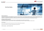
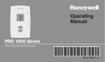
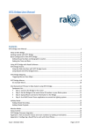
1
PL-5 Remote Controller
AP5196
User Guide
Note: This user guide describes setup and operation of the PL-5 with reference to the PL-4 and PL-11 wall plates
and an iDR system. The PL-5 may also be used with the PL-12 wall plate for remote control of a GR2 audio zone
mixer. Please see PL-12 user guide AP6506 for further details of this application.
PL-4
Introduction
The PL-5 is a stylish and compact battery powered hand
held remote controller for use with the Allen & Heath PL-4 and PL-11 wall
plates which are equipped with an IR (infra-red) sensor. It has 14 user
programmable buttons. Typically, these would be programmed by the installer
as a combination of volume up/down, signal mute, source, preset select or
MIDI messages for convenient control by the day-to-day operator. The button
layout and markings suit most typical applications. If required, the installer can
create a custom label to adhere to the controller surface. The PL-5 always
sends out the same button codes.
The associated iDR function is
independently programmed for each PL-4 or PL-11 wall plate using the iDR
System Manager software. This means that the same remote can trigger
different functions in different rooms. For example, the remote could be used
for local volume control of different zones in different rooms, or select different
sources in different rooms.
PL-11
PL-5
Removing the protective film
Before using the
controller peel off the plastic film that protects the top surface.
Replacing the battery
CR2025
3V
The PL-5 uses a CR2025 3V
lithium battery. A battery is supplied with the unit. To install or
replace the battery first remove the battery compartment cover.
Use a pointed object to press in the cover clip. Slide the cover
off. Insert the battery with + (plus) side up in the direction
shown to make contact with the spring terminal. Slide the
cover on until it clips in place.
IMPORTANT :
This
product
complies
with
the
European
Electromagnetic Compatibility directives 89/336/EEC &
92/31/EEC.
NOTE:
Any changes or modifications to the
equipment not approved by Allen & Heath could void
the compliance of the equipment. Whilst we believe
the information in this guide to be reliable we do not
assume responsibility for inaccuracies. We also reserve
the right to make changes in the interest of further
product development.
Copyright© 2009 Allen & Heath Ltd. All rights reserved.
PL-5 User Guide AP5196 issue 3
WARNING: Do not subject the PL-5 to heat or
moisture. Do not place it near heat sources such as
radiators, stoves, heat exchangers or other
appliances that produce heat.
CAUTION: Danger of explosion if the battery
is incorrectly replaced. Replace the battery with the
same or equivalent type.
Do not incinerate.
Dispose of old batteries in an environmently friendly
manner.
NOTE: Do not install the PL-4 or PL-11 wall plate in a
position subject to bright sunlight. This may reduce the
effectiveness of the IR signal.
1
How it works
Pressing a PL-5 button transmits
a code to the PL-4 or PL-11 wall plate. Each button
transmits a unique code according to which of the 14
buttons is pressed. All PL-5 controllers generate the
same set of codes.
These are chosen to limit
interaction with other equipment in the room. The IR
(infra-red) sensor in the wall plate detects the signal
and sends the code to the iDR main unit. The iDR
responds according to the function programmed by the
user for that button detected by that particular wall
plate.
Programming the button functions
The function is programmed using the iDR System
Manager software. For further details refer to the Help
file that comes with the software. Program the function
for each PL-4 or PL-11 wall plate in the system. Use
the Wallplate Settings, Infra-red window. A simulation
window is also provided for testing the system.
The function associated with each button press is
programmed independently for each wall plate. This
means that the same PL-5 controller can be used to
trigger different functions in different rooms, or that
several operators can each have their own controller to
operate the functions in any room.
The PL-5 controller transmits a directional beam of
infra-red light. This is detected by a sensor in the wall
plate when the controller is pointed at it and a button
pressed.
Typical maximum operating distance is
around 10 metres (33’) in a normally lit room. This is
reduced if the sensor is subject to sunlight.
Select the contol number for the button you want to
program. The buttons are numbered 1 to 14 as shown
below. Available functions for each button are:
Level up/down (I/P, O/P, X/P, Monitor)
How it is used
The PL-5 hand held controller
uses the PL-4 or PL-11 wall plate as a gateway to
communicate with the iDR main unit. One or more
rooms in an iDR installation may have a wall plate
installed. Each can be independently programmed to
respond to the button presses in the required way.
For example, Room 1 may use iDR output 1 as its local
audio feed, and Room 2 may use iDR output 2. A PL-4
in Room 1 may be programmed so that pressing U or
V on the controller increases or decreases the level of
output 1. The PL-4 in Room 2 may be programmed so
that the same controller buttons increase or decrease
the level of output 2 rather than output 1. This provides
local volume control using the same controller in
different rooms.
Similarly, buttons 1 to 5 may be programmed using
preset recall to select different sources. Each PL-4
may be programmed to work with different sources
according to the room. The operator simply uses the
controller buttons 1 to 5 to select the source
appropriate for each room that he/she is in.
It is not usual to install more than one PL-4 wall plate
per room. However, it may be useful to have two in a
large room, providing the convenience of control at
either end. In this case we advise that the programmed
infra-red controller functions are the same or related.
This avoids problems with both wall plates picking up
the IR at the same time due to reflections in the room.
The buttons are marked U and V , + and -, 1 to 5,
one with red border, and a further four unmarked.
These should satisfy most typical requirements. For
example, you could use U and V for volume
up/down, + and – to scroll through different sources, +
and – to adjust the tone (equalisation) through patch
changes, 1 to 5 or the unmarked keys for source select
or system patch changes, and the red key for local
audio mute or standby.
The PL-4 wall plate
In addition to the IR
sensor, this includes wall plate mounted switches,
LEDs and a rotary control which can be separately
programmed. For example, the LEDs could be used as
status indicators for functions selected using the PL-5
controller.
2
Group level up/down (I/P, O/P, XP)
Mute toggle (I/P, O/P, XP, Monitor)
Polarity toggle (I/P, O/P)
Monitor select (I/P, O/P)
Preset recall
MIDI message string
1
1
2
2
3
3
4
4
5
5
10
11
12
13
14
PL-5
6
7
8
9
Labelling the buttons
If required, the
installer can adhere a custom label to the controller
surface. We advise that this is made using a strong,
waterproof and dirt resistant material. For reference the
top to bottom dimension of the keypad area is 60mm.
Technical support For further information refer
to the iDR System Manager software Help file, the Allen
& Heath web site www.allen-heath.com, or contact
technical support in your area .
PL-5 User Guide AP5196 issue 3